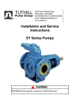
1
Service Instruction No. 67(MG)
INSTALLATION AND SERVICE
INSTRUCTIONS
MAGNETICALLY
®
COUPLED GLOBALGEAR
SERIES MG PUMPS
v 1.2
Page 1 of 14
3.19.07
WARNING
Read Manual before operating or working on a Tuthill Mag-Drive pump.
Table Of Contents
Page 4:
Page 5:
Page 5-6:
Page 6:
Page 7:
Page 8:
Page 8-9:
Page 10:
Page 11-12:
Page 13-14:
Page 14:
v 1.2
General Description / Mag-Drive Models
Pumping Principle
Proper Installation / Pressure Limitations
Magnet Temperature Limitations
Method of Drive / Pump Location / Strainer Protection
Startup
Pump Disassembly Procedure
Pump View
Pump Assembly Procedure
Troubleshooting
Material Returns
Page 2 of 14
3.19.07
WARNING
The magnets in magnetically coupled pumps create very strong magnetic fields. Special care must be
taken with the following:
Pacemakers - Magnets can upset the timing of pacemakers. These magnets should be kept away from
all pacemakers. Because of the health risks involved the importance of this cannot be overstated.
Credit Cards - Magnets can scramble the information on a credit card’s magnetic tape.
Computers, Computer Tapes and Computer Disks - Magnets can scramble the information on the
memory device.
Watches - Magnets can affect the workings of traditional mechanical spring driven watches as well as
chip and electronically controlled designs.
Electronic Instruments - Sensitive electronic instruments and devices may change calibration or be
damaged by a powerful magnetic field.
Explosive Atmosphere - Rare earth magnets and magnetic materials may create sparks through contact
in handling. Never handle rare earth magnets in explosive atmospheres because sparking may ignite the
atmosphere.
WARNING
Magnetically coupled pumps (SEALLESS - as defined by the Hydraulic Institute) do not contain any
dynamic seals. The possibility of leakage is therefore greatly reduced.
However, all materials are subject to wear and stress which can eventually lead to a failure, resulting in
leakage. Without proper safeguards, leakage of hazardous fluids is potentially dangerous and can cause
serious injury or death, or create an environmental hazard.
Users must understand and deal with this potential danger regardless which manufacturer’s pump is
used. If the fluid being pumped is hazardous, appropriate monitoring must be employed to provide early
warning of any leakage. If you are unsure of the methods available to monitor your application, you
should contact capable engineering firms for design guidance.
Magnetically coupled pumps may decouple and must be stopped to re-engage. Operation of a decoupled
unit may destroy the magnets and will result in a serious danger of explosion when handling fluids with a
low flash point because of very rapid heat buildup.
Magnetically coupled pumps are not designed to be run dry.
v 1.2
Page 3 of 14
3.19.07
General Description
The Tuthill MD Series pumps are magnetically coupled versions of the Tuthill GlobalGear Series
pumps. These pumps operate on the internal gear pumping principle described below. These pumps do
not contain any dynamic seals, thus the possibility of leakage is greatly reduced. Service Manual # 67 for
the Mag-Drive Series pumps is available at www.tuthillpump.com. See table below for available models.
WARNING
Failure to follow these instructions could result in serious bodily injury or death.
Do not attempt to work on any Tuthill pump installation before completing the steps below.
Disconnect the drive so that it cannot be started while work is being performed.
Review the Material Safety Data Sheet (MSDS) applicable to the liquid being pumped to determine
its characteristics and the precautions necessary to ensure safe handling.
Vent all pressure within the pump through the suction or discharge lines.
All Tuthill pumps contain residual hydraulic oil from the factory production test.
Determine if this is compatible with the fluid you are pumping. If the fluid is incompatible, then the pump
must be fully flushed prior to use.
Materials of
Construction
Cast Iron
Stainless
Steel
v 1.2
Pump
Size
Std. Port Size
Max. Capacity
INCH
USGPM
LPM
MD015
MD030
1 1/2 NPT
1 1/2 NPT
15
30
56.7
113.5
MD080
2” 125# Flange
80
MD015
MD030
1 1/2 NPT
1 1/2 NPT
MD080
2” 150# Flange
Max.
Speed
Max.
Differential
Pressure
Max.
Pressure
PSID
BAR
PSI
BAR
1800
1800
200
200
13.8
13.8
300
300
20.6
20.6
302.8
1500
200
13.8
300
20.6
10
20
37.8
75.7
1200
1200
150
150
10.3
10.3
300
300
20.6
20.6
50
189.2
1000
150
10.3
300
20.6
Page 4 of 14
3.19.07
The Pumping Principle
Tuthill MG Series pumps employ the internal gear pumping principle. There are only two moving
parts. Pumping action is based on a rotor, idler gear and crescent-shaped partition cast integral with the
cover.
Torque applied to the rotor is transmitted to the idler gear with which it meshes. The space
between the outside diameter of the idler and the inside diameter of the rotor is sealed by the crescent.
As the pump starts, the teeth come out of mesh, increasing the volume. This creates a partial
vacuum, drawing the liquid into the pump through the suction port.
The liquid fills the spaces between the teeth of the idler and the rotor and is carried past the
crescent partition through the pressure side of the pump.
When the teeth mesh on the pressure side, the liquid is forced from the spaces and out through
the discharge port.
Proper Installation
Unsatisfactory pump installations are usually characterized by poor suction conditions for the
specific liquid being handled. Suction conditions should be minimized to prevent vaporization of the
liquid. If vacuum conditions force the liquid to vaporize, cavitation will occur, resulting in loss of capacity,
premature wear and noisy operation.
For optimum pump performance, the suction line must be at least as large as the corresponding
pump port. It should be as short as possible in order to avoid excessive pressure drops and must be
airtight. The placement of a strainer on the suction side of the pump will restrict any solids or abrasives
from entering the pump, which could cause internal damage.
Note: Pipeline friction increases at a rapid rate with an increase in viscosity. For a given pump
and motor, larger pipelines are necessary to maintain the same pump pressure when changing from a
thin fluid to a thick one.
When handling high viscosity liquids, the speed of the pump must be reduced and the size of the
lines increased to prevent cavitation.
Under no conditions should the pump be used to support external piping loads. Piping and other
equipment should be independently supported.
The discharge line must be designed with the maximum pressure rating of the pump in mind.
Excessive pressure could cause damage to your motor and/or pump. If a pressure relief valve has not
been supplied with the pump, some other means of pressure protection must be utilized. This could
include in-line safety valves, pressure shutdown switches or other similar devices.
Every pump installation should have a good foundation. Its structure should be sufficiently strong
to hold the pump rigid and to absorb any strain or shock that may be encountered. The installation
should be leveled, checked for proper piping alignment, and then fastened securely.
v 1.2
Page 5 of 14
3.19.07
Pumps should be filled with fluid at installation and should never be allowed to run dry.
MG Series pumps have internal venting which makes them directional. The direction of rotation
is specified from the shaft end of the pump. Unless otherwise specified, rotation is assumed to be
clockwise (CW), which places the suction port on the right side of the pump when viewed from the shaft
end. Operation of the pump in a direction other than specified can cause damage to both the pump and
magnets.
Consult Tuthill personnel whenever unusual conditions of speed, pressure, vacuum or viscosity
are encountered.
The Tuthill pump is a positive displacement pump. As the pump rotates, liquid is positively
delivered to the discharge side of the pump. If the discharge line is closed off, pressure will increase until
the magnets de-couple, the drive equipment stalls and/or fails, the pump breaks or ruptures, or the piping
bursts. This could result in serious bodily injury or death. To prevent this from happening, the use of a
pressure relief valve is required. A relief valve that directs the flow back to the supply tank is
recommended.
Pumps shipped from the factory with relief valves are assembled for clockwise or
counterclockwise rotation as originally specified. The adjusting screw must always point toward the
suction line. If you want to change rotation, the relief valve assembly must be removed and turned 180°,
and the bracket must be rotated 180°.
Pressure Limitations
Standard models have pressure ratings as shown in page 4. Standard canisters are designed to
withstand the maximum rated discharge pressure of the pump. The internal venting arrangement will
normally result in a pressure in the canister that is less than the discharge pressure.
WARNING
Exceeding the maximum canister pressure may cause a canister failure resulting in the release of the
fluid being pumped. Refer to the Optional Equipment section for options available for safely addressing
this concern.
Consult the factory regarding any applications where the canister pressure is in question.
Magnet Temperature Limitations
Standard pumps are supplied with magnets constructed of Samarium-Cobalt. These magnets
cannot exceed a maximum temperature of 500° F (260° C). Operation above the maximum temperature
will result in a permanent reduction in magnet strength. Generally, all magnets subjected to temperatures
above their maximum rating will lose a portion or all of their magnetic strength.
To prevent damage to the magnets, use of a temperature sensor is recommended. Refer to the
Optional Equipment Section on the next page for further details.
v 1.2
Page 6 of 14
3.19.07
Method of Drive
Direct drive through a traditional flexible coupling is done. However, do not expect the flexible
coupling to compensate for misalignment. Contact the coupling manufacturer to determine the maximum
amount of misalignment, which the coupling can tolerate.
All pump and motor units must be properly aligned during assembly and periodically checked
since misalignment may occur later due to changing conditions.
Pipe strain can force the pump and motor shaft out of alignment. Therefore, all piping to the
pump must be properly supported. Do not allow the pump to act as a pipe support.
Provide for proper expansion of pipes when handling hot liquids. Allow pump to reach operating
temperatures and then re-check alignment.
Provide sufficient clearance, 1/16 - 1/18 inches (1.5 - 3 mm) between coupling halves with shaft
in closest operating position.
Never depend upon sight or feel. Use proper gauges when aligning a pump.
Never operate pump without all guards in place.
Pump Location
The pump should be located as close to the source of supply as conditions permit and if possible,
below the level of the liquid in the reservoir. When necessary to locate the pump in a pit, provisions
should be made to safeguard against flooding. Care must be taken to properly support the suction and
discharge piping so that no strain is put on the pump due to either weight or expansion. Piping strain can
result in misalignment, hot bearings, worn couplings, and vibration. It is important that the piping used be
clean and free of chips or scales.
Strainer Protection
Strainers are used to remove contaminated particles from the fluid system and extend pump life.
Every pump should be protected from these particles by a strainer in the suction line.
Strainer size and mesh of screen is determined by rate of flow and viscosity of fluid. Consult
strainer manufacturer for recommendations.
Never use a strainer with built-in automatic by-pass on the suction line set to open under 30 inch
(750 mm) Hg. vacuum.
Install strainer according to the designated direction of flow.
Have strainer accessible for servicing.
Use a duplex type strainer when shutdown during service is not permitted.
Provide a vacuum gauge in the suction line for determining when the strainer requires cleaning.
Make certain strainer baskets are properly reinforced so as not to collapse under 30 inch (750
mm) Hg. vacuum.
v 1.2
Page 7 of 14
3.19.07
WARNING
Follow all precautions outlined in the Material Safety Data Sheet (MSDS) applicable to the liquid being
pumped to ensure safe handling.
All Tuthill pumps contain residual test oil (Mesamol) from the factory production test. Determine if this is
compatible with the fluid you are pumping. If the fluid is incompatible, consult the factory.
Startup
Prior to starting the pump double check the following:
1.
2.
3.
4.
5.
6.
7.
8.
Pressure and vacuum gauges should be installed as close as possible to the pump.
Rotate pump shaft to ensure it turns freely without binding.
Recheck alignment and ensure all guards are in place.
Make sure piping is independently supported and no strain is being transmitted to the pump.
Make sure the safety relief valve is installed correctly.
Open suction and discharge gate valves.
Check for any leaks once gate valves are open.
Check pump rotation.
After completing these checks the pump can be started.
WARNING
The pump should not be run dry. If after approximately 60 seconds there is no discharge of liquid, stop
the pump and investigate the possible cause. Failure to comply with this could cause severe damage to
magnets, bushings and/or metal parts.
Pump Disassembly Procedure
Refer to Pump View on Page 11.
Although some minor disassembly is possible with the complete pump/motor assembly still in
place, it is recommended that the pump/motor unit be disconnected and moved to a maintenance area.
WARNING
Residual pumped fluid will be present in the pump. Follow all precautions outlined in the Material Safety
Data Sheet (MSDS) applicable to the liquid being pumped to ensure safe handling.
1. Remove piping from the ports.
2. Mark cover, housing and bracket before disassembly to ensure proper reassembly.
3. Remove the cover screws, cover, housing and idler.
v 1.2
Page 8 of 14
3.19.07
4. Inspect the following parts carefully for deep grooves, scratches or other damage:
i.
The I.D. of the housing.
ii.
The end face of the rotor.
iii.
The O.D. of the rotor.
iv.
The O.D. of the idler.
v.
The I.D. of the idler.
vi.
Both faces of the idler.
vii.
The O.D. of the idler pin.
viii.
The inside surfaces of the cover including the crescent.
5. Check for signs of wear. A decrease in capacity is generally caused by the abrasive action of
foreign materials in the liquid, resulting in excessive end clearances. End clearance can be
reduced by adjusting the thrust bearing. To adjust the end clearance, see assembly procedure.
WARNING
The pump must be separated from the magnet coupling if further disassembly is required. Follow the
instructions below.
DO NOT PLACE HAND OR FINGERS BETWEEN THE HOUSING AND ADAPTER. The magnets are
extremely strong and will attract all metallic objects and can be the source of pinch points. Do not wear
watches or other metallic jewelry when working with magnets. See warning on Page 3.
Failure to follow proper procedures or use appropriate tools could result in injury to you or damage to
either personal property or the pump.
6. Remove the screws that attach the bearing housing / outer magnet sub-assembly to the adapter.
7. Use jack screws to separate the inner and outer magnets:
i.
Place (3) guide studs into adapter at screw locations and hand-tighten.
ii.
Place (1) threaded stud into bearing housing and slowly turn the threaded stud to jack the
bearing housing / outer magnet sub-assembly out.
iii.
Continue turning the threaded stud until separation of the inner and outer magnet is
complete.
8. Remove pump bracket, rotor and canister sub-assembly from adapter.
9. Remove the canister from the bracket. The canister will probably contain residual pumping fluid.
Use care when removing, making sure to pull the canister straight off.
10. Remove the back retaining ring and remove the inner magnet.
11. Set magnet down on a clean, non-magnetic surface; inspect the magnet sleeve for evidence of
damage or excessive wear and cover with a cloth to prevent contamination.
12. Remove the front retaining ring (if equipped).
13. Loosen the setscrews and remove the adjusting ring. Check for excessive wear. Check the shaft
O.D. For any burrs and remove to prevent damage to the bracket bushings.
14. Remove the rotor from the bracket.
15. The back face of the rotor and the bracket face should be inspected for any deep scratches or
wear. Inspect the bushing in the bracket for wear.
16. Do not remove the o-ring from the bracket unless it is worn or damaged and needs replacement.
See Next Page For Pump View
v 1.2
Page 9 of 14
3.19.07
v 1.2
Page 10 of 14
3.19.07
Pump Assembly Procedure
Refer to Page 11
1.
2.
3.
4.
5.
6.
Clean all parts thoroughly.
Install rotor in bracket.
Assemble housing & gasket to bracket with bracket screws.
Assemble idler, cover & gasket to housing with housing screws.
Install the thrust bearing, but do not tighten the setscrews yet.
Set End Clearance:
i.
The positioning of the adjusting ring is used to set and maintain proper internal
clearances. These clearances depend on the size of the pump and are shown below.
Note: Some Tuthill pumps are provided with non-standard clearances for use with highviscosity or high-temperature fluids. Consult the factory for clearances of these pumps.
ii.
iii.
iv.
v.
Pump Model
(Iron)
End Clearance
(inch)
Pump Model
(Stainless)
End Clearance
(inch)
MD015
MD030
.003 - .005
.003 - .005
MD015
MD030
.006 - .008
.006 - .008
MD080
.006 - .008
MD080
.008 - .010
Obtain a feeler gage with a thickness equal to the desired end clearance.
Insert the feeler gage through the ports, between the idler and the rotor.
Push the rotor towards the cover, and tighten the thrust bearing setscrews.
Remove the feeler gage, and rotate the shaft to ensure smooth operation before
proceeding.
7. Place pump on flat surface with the shaft facing upward. Check condition of o-ring in the groove
on the bracket. Install new o-ring if required.
8. If equipped, place retaining ring into lower retaining ring groove on shaft.
9. Place key into shaft keyway.
10. Lower inner magnet onto shaft until it bottoms onto retaining ring or shaft shoulder. Place
retaining ring into retaining ring groove on shaft
11. Place canister over inner magnet until the face of the canister flange bottoms onto the bracket.
To insure easy assembly of canister over o-ring, place a small amount of lubricating oil on
canister I.D. before assembly.
12. Position adapter securely on flat surface with the pump register end facing upward. Carefully
lower the pump/inner magnet sub-assembly into the adapter register.
13. Once the pump/inner magnet sub-assembly is in place, fasten it to the adapter with screws.
14. Place pump/inner magnet sub-assembly on a flat surface with the bearing housing register end
facing upward.
15. Place key into bearing housing shaft keyway.
16. Place bearing housing sub-assembly on a flat surface with shaft facing upward.
17. Carefully lower outer magnet onto shaft until outer magnet bottoms onto shaft shoulder.
18. Lock outer magnet onto shaft with setscrews, installing the cone-pointed setscrew first.
WARNING
DO NOT PLACE HAND OR FINGERS BETWEEN THE BRACKET AND ADAPTER. The magnets
are extremely strong and will attract all metallic objects and can be the source of pinch points. Do
not wear watches or other metallic jewelry when working with magnets. See warning on page 3.
Failure to follow proper procedures or use appropriate tools could result in injury to you or damage to
either personal property or the pump.
v 1.2
Page 11 of 14
3.19.07
19. Install outer magnet assembly. Use jack screws to control the attraction of the inner and outer
magnets:
i.
Place (3) guide studs into adapter through the bracket screw clearance holes and handtighten.
ii.
Screw (1) jackscrew into bearing housing until it extends to the end of the outer magnet.
iii.
Slowly unscrew jackscrew from bearing housing. This will lower sub-assembly into
adapter register.
iv.
After magnet bearing housing sub-assembly has been lowered into place, remove guide
studs and jack screw.
20. Secure bearing housing sub-assembly into place with screws.
21. Proceed to couple completely assembled unit to drive.
v 1.2
Page 12 of 14
3.19.07
Troubleshooting
1. Problem: No fluid is delivered.
a. Power is not on.
b. Net positive suction head available (NPSHa) is lower than required for the vapor pressure of the
liquid pumped. You should calculate NPSHa and redesign piping, if necessary.
c. Leaks in suction line or port passages. These can be detected by submerging pressure line from
discharge side of pump into a pail of liquid where the air will be seen in the form of bubbles.
d. Direction of shaft rotation is incorrect.
e. Magnetic coupling has decoupled. Check for excessive pressure/speed problems.
f. Relief valve setting is too low. Liquid is discharging through the by-pass port.
2. Problem: Capacity is too low.
a. Air leaks in suction line.
b. Suction losses are too high. The suction lift is too great or the suction line is too small or too long.
This can be detected by installing a vacuum gauge directly at the pump suction. The maximum
vacuum at the pump suction should never exceed 15” of mercury. Vaporization caused by higher
vacuums will generally result in capacity drop off. Redesign suction conditions.
c. Pump speed is too slow.
d. Strainer too small or obstructed.
e. Suction pipe or port not immersed in liquid deep enough
f. Piping improperly installed permitting air pocket to form in the pump.
g. Increased clearances or wear in the pump will sometimes cause the pump to deliver an
insufficient supply of liquid. This may be corrected by reducing the thickness of the cover
gaskets. A folded gasket or a slight amount of dirt can exaggerate the problem and cause
leakage. Refer to Assembly Procedure section for minimum end clearances.
3. Problem: Pump works spasmodically.
a. Leaky suction lines.
b. Suction conditions vary.
c. Air or vapor in liquid.
4. Problem: Excessive power draw.
a.
b.
c.
d.
e.
Pressure too high.
Liquid more viscous than originally expected.
Suction or discharge lines obstructed.
Insufficient horsepower.
Mechanical defects:
i.
Drive shaft and pump are misaligned.
ii.
Pump is binding due to insufficient end clearance.
iii.
Pump shaft is bent.
iv.
Misalignment within pump due to bad piping or poor installation, causing strain or
distortion.
5. Problem: Pump is noisy.
a.
b.
c.
d.
e.
v 1.2
Pump is cavitating due to inadequate suction conditions.
Misalignment of coupling.
Coupling set too close to pump.
Vibrations of pump due to worn or bent shaft.
Air leaks on suction side of pump or air entrainment in fluid.
Page 13 of 14
3.19.07
6. Problem: Pump leaks.
a. Bolts need tightening, allowing gaskets or o-rings to leak.
b. Gaskets or o-rings are damaged.
c. Damage has occurred to the canister.
Material Returns
If it becomes necessary to return a pump to the factory, a Return Goods Authorization (RGA)
must be obtained from either your local Authorized Distributor or our Alsip plant. No RGA can be issued
until a completed Material Safety Data Sheet (MSDS) has been forwarded to our Alsip plant and return of
the pump approved.
•
•
•
v 1.2
Tuthill pumps are precision built and must be handled with care.
Pumps must be drained of all fluid and the ports plugged to prevent foreign material from
getting into the pump.
Pumps must be packaged securely to prevent damage while in transit.
Page 14 of 14
3.19.07