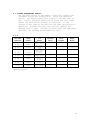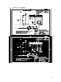
1
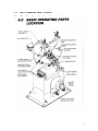
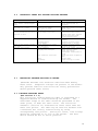
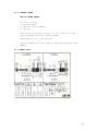
MICRO PRODUCTS COMPANY
MANUFACTURES OF PRECISION
WELDING MACHINES
MODEL E1S BUTT WELDER
MODEL E1C BUTT WLEDER
SERVICE MANUAL
REVISED 2002
1
TABLE OF CONTENTS
1.0
2.0
3.0
4.0
5.0
6.0
7.0
8.0
9.0
10.0
11.0
12.0
13.0
1.0
SPECIFICATIONS
GENERAL OPERATING INSTRUCTIONS
BASIC OPERATING PARTS
BASIC OPERATING PARTS LOCATION
TYPICAL OPERATING SEQUENCE
SPECIAL ADJUSTMENT
PREVENTIVE MAINTENANCE
SUGGESTED SETTINGS
DIAGNOSTIC CHART FOR TROUBLE SHOOTING
ELECTRICAL SCHEMATIC
SAFETY REMINDERS
BUYERS GUIDE
PARTS LIST
SPECIFICATIONS
MODEL E1S FERROUS
Stock Size Range
Type Material
Operating Voltage
Input Power Cycle
Line Demand
Single Phase
Weld Transformer
Truck Mounted Welder
Floor Space
Overall Height
Height to Welding Dies
Welder Weight
SUITABLE FOR BENCH MOUNTING
Dimensions
Overall Height
Base Dimensions
Height from Base to Welding Dies
Welder Weight
.010” to .062” Diameter
High and Low Carbon Steel and
Steel Alloys
115 Volts
60 Cycle
(50 or 25 Cycle Optional)
3 Amperes @100% Duty Cycle
10 Amperes @10% Duty Cycle
0.5 KVA @50% Duty Cycle
2 Stationary Casters
2 Swivel Casters
24” x 24”
54”
45”
Approx. 100 LBS
20”
9” x 7”
12”
Approx. 50 LBS.
2
MODEL E1C NON-FERROUS
Stock Size Range
Type Material
Operating Voltage
Input Power Cycle
Line Demand
Single Phase
Weld Transformer
Truck Mounted Welder
Floor Space
Overall Height
Height to Welding Dies
Welder Weight
SUITABLE FOR BENCH MOUNTING
Dimensions
Overall Height
Base Dimensions
Height from Base to Welding Dies
Welder Weight
.015” to .050” Diameter
Copper, Brass, Bronze, Aluminum and
Non-ferrous Alloy
115 Volts
60 Cycle
(50 or 25 Cycle Optional)
6 Amperes @ 100% Duty Cycle
19 Amperes @ 10% Duty Cycle
1.0 KVA @ 50% Duty Cycle
2 Stationary Casters
2 Swivel Casters
24” x 24”
54”
45”
Approx. 100 LBS
20”
9” x 7”
12”
Approx. 50 LBS.
2.0
GENERAL OPERATING INSTRUCTIONS
2.1
ELECTRICAL HOOK-UP INSTRUCTIONS
First determine that available electrical service in your
plant corresponds to the nameplate rating located on welder
housing. Electrical wiring to welder must be of sufficient
size to deliver full ampere load with no appreciable loss
during the weld cycle. The welder will not operate
properly if there is more than a 10% variation in the line
voltage. In general, the welder should be fused with a
slow blow fuse of the 100% duty cycle rating. The minimum
power cable size to the welder can be obtained by using
this same current rating.
Refer to National Electrical Code and local electrical
regulations for adequate power sizes; disconnect methods
and fusing guidelines.
Remember line voltages to the welding machine are
potentially dangerous should the power cords be damaged or
severed. The welding voltages at the welding dies will not
harm an operator since they do not exceed 10 volts.
3
2.2
SAFETY PRECAUTIONS
2.2.1 ELECTRICAL
Maintain electrical cables to welder in good repair.
Welders must be grounded and connections securely
tightened. Heat switch must not be changed to a new
position while a weld cycle is in process. Disconnect
electrical service before servicing the welder – high
voltages are located within the base of the welder.
2.2.2 MECHANICAL
Operator while using welder must wear safety glasses. Keep
all safety guards on welders and use properly. Operators
must be instructed on the basic operation of unit to
prevent injury. Check nameplate rating and keep within
material size range for each welder.
2.3
WELDING DIES
The dies and shoes supplied with the welder will handle
most size and material types within the range of the
welder. For new weld applications consult the factory for
special die and shoe sets.
3.0
BASIC OPERATING PARTS
3.1
WELD HEAT SELECTION SWITCH
Weld heat is selected by means of a tap switch with 10
steps of voltage. Number one indicates the highest setting
and number ten the lowest. The switch is located in the
front and center of the welder. (Ref. 4.0)
3.2
HEAD CLOSED SPACE SETTING
Turning the insulated screw that rides the space-adjusting
cam located on the top of the headpiece makes this
adjustment.
3.3
HEAD OPEN SPACE SETTING
A space-adjusting cam located on the top of the headpiece
makes this adjustment. This setting determines the amount
of burr that the weld will have. See charts for
approximate settings.
4
3.4
LIMIT SWITCH SETTING
The weld limit switch controls the cutoff point of current
flow to the welding dies. Turning an adjusting screw
located on the left end of the movable headpiece makes this
adjustment. See Charts for setting.
3.5
UPSET PRESSURE
Upset pressure adjustments are obtained by rotating the
knurled knob on the right hand side of the stationary
headpiece. When the outside edge of the adjusting screw is
flush with outside edge of the knurled knob, the movable
headpiece should just close when pulled to the left by hand
and released. A calibrating screw and nuts located on the
opposite left hand headpiece will assist in setting this
positioning. Accompanying charts will assist in correct
settings for various sizes of wire.
3.6
WELD INITIATING KNOB
The push button knob that initiates the weld cycle is
located on the right end of the stationary headpiece.
5
4.0
BASIC OPERATING PARTS LOCATION
6
5.0
TYPICAL OPERATING SEQUENCE
Wire to be joined must be free of rust, corrosion or other
insulating materials, clean wire where it makes contact
with welding dies.
1.
2.
3.
4.
5.
6.
7.
8.
9.
10.
Adjust weld heat knob to proper setting.
Adjust tension-indicating knot to correspond to chart
settings.
Rotate space-adjusting cam to correspond to chart
settings.
Square cut each end of wire with cutter provided on
unit
Place wires in correct welding die groove, so ends
touch midway between open jaws.
Move magnifying glass away from weld area to prevent
lens damage.
Rotate space adjusting cam handle to rear to ready
unit for weld.
Push operating switch located on right hand headpiece
and hold until weld is completed (less than 2 seconds
required.)
Release clamp fingers and remove wire.
Hard drawn material or high carbon steel will require
an anneal operation, handle carefully prior to anneal
to prevent fracturing a brittle weld.
7
5.1
WELDING STRANDED MATERIALSCOPPER, ALUMINUM AND STEEL
A standard welding cycle of MICRO-WELD Model E1C and E1S is
easily accomplished as noted in front portion of this
manual.
Butt-welding of stranded materials at times may cause
problems because of its multi-wire configuration. Stranded
wire ends may be severed and fused electrically, on either
unit, prior to welding to prevent fraying of the material.
A.
B.
C.
D.
E.
F.
G.
H.
I.
5.2
Place spacing cam on #3.
Open clamp fingers and place stranded material
across and into closest fitting die groove so it
bridges the space between the dies.
Release clamp fingers clamping material securely
into the die groove.
Push operating switch, which will in turn pass
current through the material.
The current passing through the stock
instantaneously severs and fuses the material.
Note: Experiment with a heat, setting which will
Produce the soundest fusion.
Release clamp fingers and discard the short piece
of scrap.
Place second stranded wire into jaws and proceed
as noted above.
At this time the two fused cables or conductors
may be butt welded with standard techniques.
Trim off or swage burr to parent material size.
E1S – BURNOFF
To sever stranded steel cable, set space cam on #2. Place
the cable in the proper groove, press-operating switch to
sever it. Raise or lower Heat Switch setting to establish
the best burn off condition.
5.3
ANNEALING PROCEDURE
5.3.1 STANDARD ANNEAL –
Section 4.0
1.
Place space cam between #1 and #2 so the electrical
circuit is completed.
2.
Carefully place wire into spring anneal posts with
weld upset burr midway between posts.
3.
Push operating switch located on right hand headpiece.
4.
Allow wire to heat up to desired anneal temperature.
8
5.3.2 DIAL INDICATING ANNEAL – OPTIONAL
1.
Carefully place wire into stationary anneal clamp
(right hand side) and clamp into position.
2.
Rotate movable clamp jaw to its extreme right hand
position and clamp wire into jaws. Weld burr should
be approximately midway between anneal clamps. Note
distance between jaws may be varied to suit a variety
of sizes. More accurate anneal will result if smaller
diameter wires are annealed in a corresponding close
position.
3.
Push anneal button located on base of welder.
4.
Allow wire to heat and observe the following:
a. When heat is applied to wire, expansion of wire
will occur.
b. The dial indicator will start to move.
c. When critical anneal temperature is reached, the
needle will come to rest momentarily.
d. In sequence, the needle will drop back slightly and
move forward again.
5.
At the beginning of the forward movement of the
needle, release the anneal button.
6.
Anneal cycles allowed to continue beyond this point
will not be annealed uniformly.
5.3.3 FRONT TYPE ANNEAL – Section 4.0
1.
Directions for dial type anneal maybe followed.
2.
No dial device is furnished, so anneal temperature and
rate of expansion is visually observed.
9
6.0
SPECIAL ADJUSTMENT
6.1
HEADPIECE CLOSED SPACE ADJUSTMENT
Closed space between dies should be 1/64” when the Space
Adjusting Cam is set at zero.
To make this adjustment first move the Space Adjustment Cam
to zero, then check the spacing between the dies.
If the space between the dies is not 1/64” at this time,
loosen the locknut on the Space Adjusting Screw. Turn
screw clockwise for more space and counterclockwise for
less space. Once the space has been set tighten the
locknut on the Space Adjusting Screw.
6.2
OPEN SPACE ADJUSTMENT
This adjustment determines the amount of upset burr. The
adjustment is made by the space-adjusting cam. A pointer
reflects the cam position. Refer to accompanying charts
for approximate setting.
6.3
WELD LIMIT SWITCH
Do not put any wire in the dies when making this
adjustment. Set the Space Adjusting Cam at #1 on cam.
With a voltmeter measure across the clamp fingers with
power applied to the welder. Press the weld button. The
voltmeter reading should be approximately 3 VAC with welder
at the highest heat setting. If no voltage is read move
the Space Cam to a higher number. Return the cam to #1
while watching the voltmeter. The voltage should shut off
at #1 on the cam.
Loosen locknut on the Limit Switch Adjusting Screw and
adjust until welder shuts off at #1 on the Space Adjusting
Cam. After setting tighten locknut on the Limit Switch
Adjusting Cam, then tighten the locknut on the Limit Switch
Adjust screw.
6.4
UPSET PRESSURE
Upset pressure adjustments are obtained by rotating knurled
knob on right hand side of stationary headpiece. When
outside edge of upset adjusting screw is flush with outside
edge of thumb knob, movable headpiece should just close
when pulled to the left by hand. A calibrating screw and
nut located on opposite left hand headpiece will assist in
setting the neutral position. Accompanying charts will
assist in correct setting for various sizes of wire.
10
7.0
PREVENTIVE MAINTENANCE
7.1
AS REQUIRED:
Flashings must be removed from between welding dies and
clamp fingers with a brush. If flashings are attached so
that they cannot be removed by brushing with a soft wire
brush, they may be broken loose with a scraper made of
fiber or wood.
7.2
DAILY:
7.2.1 Check condition of welding dies and clamp fingers. Replace
Dies or clamp fingers when they have become so worn that
stock does not align or there is slipping of stock in the
dies during upset pressure.
7.2.2 Check condition of clamp springs. Replace all broken
springs or springs that have taken a set.
7.2.3 Check movable head for excessive wear. Have new slide
shafts installed and die seats machined if stock does not
line up when placed in die grooves.
7.3
MONTHLY:
7.3.1 Remove welding dies and clean bottom of die surface with
#120 emery cloth. Do this by placing the emery cloth on a
flat surface plate and rubbing the dies on it, keeping the
surface of the die flat. Wipe die and die seat with a
clean cloth and replace, taking care not to touch either
contact surface with the hand.
7.3.2 Check anneal dies and replace worn or broken parts.
7.3.3 Check insulating fiber pin on limit switch adjusting screw
for broken or frayed ends.
7.3.4 Check upset tension spring and clamp springs. Replace if
springs have been over-stretched and will not return to
normal position.
7.4
QUARTERLY:
7.4.1 Disconnect power to welder. Check contacts on operating
and limit switch. Replace those that are burned.
7.4.2 Check anneal dies and replace worn or broken parts.
7.4.3 Check insulating fiber pin on limit switch adjusting screw
for broken or frayed ends.
7.4.4 Check upset tension spring and clamp springs. Replace if
springs have been over-stretched and will not return to
normal position.
11
7.5
ANNUALLY:
7.5.1 Remove the movable headpiece and check condition of slide
shafts. Wash slide shafts with low residue cleaner,
lightly oil, than reassemble the headpiece.
7.5.2 Check condition of headpiece castings. If worn or broken,
replace with new headpiece. If welder is used in an area
where there are corrosive fumes, clean off all oxides and
paint where possible.
7.6
WELDING DIE INFORMATION
Description:
Welding dies – Lower conducting electrode and clamp jaw.
Welding clamp fingers – Upper clamping member.
WELDING DIES IN POOR CONDITION ARE THE MAIN CAUSES OF BAD
WELDS.
7.6.0 CARE OF DIE SETS
7.6.1 Use a Brass or fiber blade to remove particles of flashings
that build-up on die sets. Excessive flash build-up causes
die burns on material and shorting of die sets.
7.6.2 Do not attempt to clamp material that is not suited for
welder into die sets. Undersize materials will slip and
burn die grooves, oversized materials will overstress
clamping parts.
7.6.3 Do not use welding die sets for a vise. These parts will
not withstand the mechanical abuse.
7.6.4 Whenever welding dies are replaces, clean bottoms of dies
and corresponding die seats to a bright and clean condition
before bolting them tightly into place. An oxidized surface will insulate
the welding dies and reduce effective welding voltage.
7.6.5 Welding die sets will wear with use and must be changed
occasionally for good welding results. Keep and adequate
supply of replacement parts available. Wire and rod
slippage is a problem caused by poor die sets and a major
cause of wire breaks.
12
8.0
SIZE
.010
.020
.030
.040
.050
.062
.015
.020
.025
.030
.040
.050
.015
.025
.032
.040
.051
.015
.020
.025
.032
.050
SUGGESTED SETTINGS
MATERIAL
Steel
Steel
Steel
Steel
Steel
Steel
Copper
Copper
Copper
Copper
Copper
Copper
Brass
Brass
Brass
Brass
Brass
EC
Aluminum
EC
Aluminum
EC
Aluminum
EC
Aluminum
EC
Aluminum
DIE
GROOVE
Front
Front
Middle
Middle
Rear
Rear
Front
Front
Middle
Middle
Rear
Rear
Front
Middle
Middle
Rear
Rear
HEAT
10
8
6
4
2
1
7
4
1
8
6
4
8
5
1
9
7
SPACE
2
2
3
4
6
8
1 1/2
2
2 1/2
3
4
5
2
2
2 1/2
3
3 1/2
TENSION
1
1
1 1/2
1 1/2
2
2 1/2
1
1 1/2
1 1/2
2
2
2 1/2
1
1 /1/2
1 1/2
2
2
RANGE
Low
Low
Low
Low
Low
Low
Low
Low
Low
High
High
High
Low
Low
Low
High
High
Front
8
1 1/2
1
Low
Middle
5
2
1 1/2
Low
Middle
1
2 1/2
1 1/2
Low
Middle
7
2 1/2
2
High
Rear
5
3
2
High
ANNEAL
SPACE
NOTE: These settings are approximate and may be varied to
suit needs.
13
9.0
DIAGNOSTIC CHART FOR TROUBLE-SHOOTING WELDERS
WELDING ACTION
Weld action normal but weld
burr doesn’t extend beyond
wire
Molten metal is blown out
and ends not joined
Weld has complete burr but
is dry and breaks off below
surface of wire
Weld good but poorly aligned
Ends of wire buckle and may
not weld
Varying weld results
CAUSE
Lack of spacing space
Weld heat too high
Stock is too small
Low upset pressure
Upset pressure too great
High carbon steel wire
Welding dies & clamp fingers
Starting space
Loose shafts
Upset pressure too great
Low weld heat
Stock slipping
Varying weld voltages
Rod condition variations
Dies
Flashings
9.1
REMEDY
Increase starting space
until desired burr is
obtained
Lower heat settings
Check size rating of welder
Adjust upset
Lower upset pressure
Carbon-steel wire often
appears like this, process
wire by annealing weld
before removing burr
Replace worn dies and clamp
fingers
Decrease starting space
Return heads to factory
Decrease starting space
Increase weld heat
Check Clamp finger pressure
Check electric lines
Clean and tighten
transformer connections to
heads
Clean Rod where clamped in
dies
Replace dies
Clean build-up of flash
materials
ELECTRICAL TROUBLE-SHOOTING OF WELDER
(CAUTION! Extreme care should be exercised when making
these tests. Dangerous voltages are present in the welder.
Only persons familiar with electrical safety precautions
should perform these tests.)
9.1.1 TROUBLE-SHOOTING TABLE
(See section 9.1.3)
This electrical trouble-shooting table is furnished as a
suggested method of trouble-shooting the welder. The
individual steps of the table should be performed in the
order given, to make the tests valid. The electrical
schematic (section 10) furnished for these tests show the
table test points. The table may be used for welders with
a different but closely related wiring by using
corresponding test points. (During all tests, line voltage
should be connected to L1 & L2 of the welder. The heat
switch should be set to the #1 position.
14
9.1.2 FINAL ELECTRICAL CHECKS
Set the heat switch to the number 1 position, connect the
voltmeter across the welding dies. Press the operating
switch. The meter reading will typically be less than 10
VAC. Consult the weld specification sheet for this value.
Rotate the heat switch through all settings. If the
voltage is not read at any setting, the heat switch may be
defective. Actuate the weld limit switch; observe the
reading goes to zero. Release the weld limit and operating
switches, the reading should remain at zero.
9.1.3
TEST LEAD
CONNECTION
METER
READING
L1 PB2-1
115VAC
L1 PB2-2
115VAC
L1 LS1-1
115VAC
L1 LS1-2
115VAC
L1 PB1-1
115VAC
L1 PB1-2
115VAC
L1 S2-1
115VAC
PROBLEM
IF NO
READING
Open wire to
anneal switch
Bad anneal
switch
Open
connection to
weld limit
switch
Open weld
limit switch
Open wire to
operating
switch
Bad operating
switch
Open wire to
heat switch
PRESS
OPERATING
SWITCH
WELD LMIT
SWITCH
ACTUATED
PRESS
ANNEAL
SWITCH
X
X
X
X
X
Note: to perform repair consult section 13 for parts
identification.
15
10.
ELECTRICAL SCHEMATIC
16
11.0 SAFETY REMINDERS
The following accident prevention information is presented
to eliminate potential hazards while operating, inspecting
or repairing Micro-Weld Electric resistance welding
equipment.
Important safety compliance information for Micro-Weld
Welders.
GENERAL
1.
Qualified personnel, prior to using equipment, must
instruct an operator on basic operation and
malfunction methods.
2.
Safety eyeglasses must be worn by all personnel
operating or servicing welders.
3.
Use safety equipment properly and keep safety
equipment on welders.
4.
Determine that both operating voltages and hertz
(cycles) of power supply correspond to ratings listed
on welder nameplate located on welder housing.
5.
Check nameplate ratings and keep within capacities and
material categories stated therein.
6.
Adjustments or repairs must be made by persons
thoroughly familiar with operating principles of
welder.
7.
Welder must be disconnected from power supply prior to
maintenance or repair procedures.
ELECTRICAL
1.
Refer to national Electrical Code and local
regulations for adequate electrical wiring to power
welder. Do not operate welder with inadequate
electrical power supply cords or cable.
2.
All welders must be grounded through power supply and
welder ground connection terminal securely tightened.
3.
All welders must be able to be disconnected from power
source either by a double breaking disconnect switch
or unplugged by standard rated plugs.
4.
All welders must be fused to prevent injury should an
electrical malfunction occur. Welders must never be
fused for an ampere load that exceeds the ratings
stated on welder nameplate. Normally welders are fused
using the nameplate rated load; time lag parameters
functional to standard fuse allow this specification.
5.
Electric power cords to welder must be kept in good
condition. Report any damage or potential hazards to
maintenance personnel.
6.
The weld head selection switch, potentiometer or range
selection devices must not be changed to a new
position while a weld operation is in process.
17
12.0 BUYERS GUIDE
HOW TO ORDER PARTS:
You must provide
1. Machine Model
2. Machine Serial Number
3. Voltage
Then identify part(s) on part list in section 13 and
provide MICRO with the circled number
CALL MICRO at A.C. 630-787-9350
Provide MICRO with your company name and purchase order
number.
13.0 PARTS LIST
18
PARTS LIST E1S, E1C
MODEL /
PART NO.
E1-02
E1-03
E1-04
E1-05A
E1-06A
E1-07A
E1-21
E1-22
E1-23
E1-23A
E1-24
E1-25A
E1-26
E1-27
E1-28
E1-19
E1-70A
E1-72A
E1-74
E1-75
E1-76
E1-77
E1-38
E1-39
E1-40
E1-55
E1-S100S
E1-100C
E1-68
E1-69
E1-90
E1-92
E1-89
E1-93
DESCRIPTION
ITEM NO
Welder base
Welder transformer housing
Welder transformer cap
Headpiece stationary casting
Movable casting match
Headpiece assembly with all operating
Parts and electrical switch (steel)
(Copper)
Headpiece overthrow stop screw
& nuts
Tension adjusting knob
Tension adjusting worm with scale
Tension adjusting spring, standard
Tension adjusting spring, light duty
Tension spring retaining screw & nut
Space adjusting cam and handle assembly
Space adjusting cam repeatable stop
Space adjusting cam bushing
Space adjusting cam attaching screw
Space and nut adjusting screw
Clamp fingers, pair, wide tip
Clamp fingers, pair, narrow tip
Clamp finger stop pin and locknut
Clamp finger return spring
Clamp finger return spring attaching
Screw and nut
Clamp finger attaching screw and locknut
Limit switch cover
Limit switch cover attaching screw with
Insulation
Operating switch button, inner and outer
with screw
Limit switch adjusting screw & locknut
Limit and operating switch assembly,
complete for steel welders
Limit and operating switch assembly,
Complete for copper and aluminum welders
Welding dies, pair
Welding die attaching screw, 2 required
Switch, anneal, single pole type
Switch, anneal, nameplate
Switch, high-low
Switch, high-low, nameplate
42003
52005
32012
32010
32011
32028
35564
35568
80002
80004
32035
32003
32000
32002
90217
32016 - 17
32018 - 19
32020
80007
91025
32064
32004
91055
32005
52008
56507
56508
32024
90702
32089
48307
57839
48306
19
PARTS LIST E1S, E1C
MODEL/
PART NO.
E1-58
E1-07
E1-08
E1-09
E1-10
E1-11
E1-11A
E1-11B
E1-59
E1-65
E1-66
E1-67
E1-88
E1-94
E1-96
E1-97
E1-102
E1-103
E1-104
E1-105
E1-113
E1-114S
E1-114R
E1-114W
E1-115
E1-119
E1-16B
E1-15HB
E1-19HB
E1-17HBC
E1-20HB
E1-81
E1-82
E1-83
E1-84
E1-85
E1-86
E1-87
E1-30
DESCRIPTION
ITEM NO.
Anneal pin with retaining clip, 2 required
Anneal frame stationary
Anneal frame movable
Anneal bar adjustable
Anneal bar locking screw
Anneal frame bearing center, adjustable
Anneal frame bearing center, fixed
Anneal frame bearing nylon
Anneal die with mounting screw, lower
2 required
Anneal die shoe compression spring
Anneal die shoe compression spring,
2 required
Anneal die shoe compression spring mounting
Screw and nut, 2 required
Anneal frame flexible power shunt
Dial indicator assembly with mounting case
Dial indicator contact button
Dial indicator attaching screw, insulated
Washers and nut
Heat selection switch, 10 taps, 10 amps
Heat selection switch knob, 10 amp type
Heat selection switch housing
Heat selection switch housing attaching
screw, 2 required
Truck assembly, complete with foot release
Mechanism
Caster assembly, swivel type
Caster assembly, rigid type
Caster wheel only, either rigid or swivel
Vise
Complete shear assembly with mounting
Bracket
Mounting bracket
Shear handle
Shear stop cam and screw
Shear cutter blades, pair
Shear cutter blades attaching screw & nut
Lamp assembly complete
Lamp post
Lamp post holder
Lamp bulb, 25 watt, 120 volts
Lamp receptacle, standard base
Lamp shade casting, upper
Lampshade casting, lower
Magnifying glass and frame
32029
62003
62004
62000
93069
62001
62148
62002
62009
32030
80005
91028
62006
77851
62012
90203
57800
48214
42001
91048
42005
48100
48101
60000
64002
64001
64000
64004
64042
64021
52006
52007
52003
58151
58166
32013
78601
20
PARTS LIST E1S, E1C
MODEL/
PAT NO.
E1-30B
E1-137
E1-140
E1-141
E1-142
E1-31
E1-32
E1-34
DESCRIPTION
ITEM NO.
Magnifying glass and bracket assembly
Guard, flash shield
Welding transformer, 120 volts, 60 hertz –
Application: Copper and aluminum wire –
State serial number of welder
Welding transformer, 102 volts, 60 hertz –
Application: Steel wire, standard anneal –
Note: welder has combination operating and
Anneal switch.
State serial number of welder
Welding transformer, 120 volts, 60 hertz –
Application: Steel wire, front anneal –
Note: welder has separate anneal switch
Located on front lower base –
State serial number of welder
Insulating fiber washer, transformer strap
Insulating sleeve, transformer strap
Attaching screw, transformer strap
68005
32069
52014
52015
52016
37728
37709
90202
21
22