1
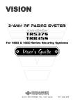
series
1480
DIGI ∞ LINK SMART
FAC TORY KEYL ESS UPGRADE SECURIT Y
© 2011-2015 KIRAMEK, INC., Aichi Japan
Ver. 1.9, Aug. 2015
Thank you for purchasing this VISION
1480 Vehicle Security System. The 1480
is a state of the art device that will provide you with years of trouble free service if used properly. Please familiarize
yourself with the content of this Owner’s
Guide to get the most out of your new
system. We trust you will enjoy using the
product.
TABL E OF CONTENTS
Limited Lifetime Warranty ................................... 1
Included Items ............................................ 2
Arming & Disarming ....................................... 3
Arming ................................................ 3
Confirmation Chirps .................................... 3
Disarming ............................................. 4
Manual Disarming ...................................... 5
Main Features ............................................ 6
Trunk Release Bypass .................................... 6
Door Trigger ........................................... 6
2-Stage Shock Sensor ................................... 6
Ignition Trigger ......................................... 7
Hood Trigger ........................................... 8
Error Chirp ............................................. 8
GWA (Ground When Armed) ............................. 8
SBS (Sector Bypass System) ............................... 8
Status LED ............................................. 9
Hazard Flash .......................................... 10
Resume .............................................. 10
Valet Mode ........................................... 10
Programmable Features ................................... 11
Troubleshooting .......................................... 14
Options ................................................. 16
NOTICE! Although reasonable efforts have been taken to ensure accuracy in this
Owner’s Guide, Kiramek Inc. shall not be held liable for any errors, omissions, property damage, or injury resulting from the use of this information.
All product specifications and features are subject to change without notice.
© 2011-2015 KIRAMEK, INC.
L imited L ifetime Warrant y
The VISION 1480 Control Module is backed by a limited lifetime warranty against defective components and/or improper product assembly
to the original purchaser for as long the vehicle is owned by that same
purchaser, contingent upon installation by an Authorized VISION Dealer. All product warranties become void if the VISION 1480 system was
not sold and installed by an Authorized VISION Dealer or the system
is moved to another vehicle. All other parts and/or accessories that
connect to VISION 1480 systems, including but not limited to the Siren,
Shock Sensor and LED Program Switch, are warranted for one (1) year
from the original date of purchase.
During the warranty period, Kiramek Inc. will repair or replace, at its
sole discretion, any system component that is found defective in material or assembly during the warranty period, provided that the product
is returned to Kiramek Inc. by an Authorized VISION Dealer and is accompanied by a clear and legible copy of the original purchaser’s receipt.
Any damage to your VISION 1480 system that results from normal
wear-and-tear, accidents, improper use, neglect, faulty wiring, incorrect
installation, modification, removal or defacement of the product serial
number, alteration or repair outside Kiramek Inc or its Authorized VISION Dealers immediately voids this warranty.
This warranty is limited to defective parts only and does not provide
any compensation whatsoever for damages associated with the VISION
1480 system or its accessories. This warranty does not cover installation labor, product removal and/or reinstallation fees. This warranty
is valid for the original purchaser only and may not be transferred to
another party. Kiramek Inc makes no warranty against theft or vandalism of the vehicle in which the VISION 1480 system was installed. This
warranty shall not be interpreted as an insurance policy against loss,
nor shall Kiramek Inc be liable any in way for such loss, financial or
otherwise.
WARNING! DO NOT ATTEMPT TO INSTALL THIS VISION 1480 PRODUCT YOURSELF BECAUSE SUCH WILL IMMEDIATELY VOID THE WARRANTY. THIS SECURITY SYSTEM MUST BE PROFESSIONALLY INSTALLED BY YOUR AUTHORIZED
VISION DEALER TO VALIDATE YOUR WARRANTY.
KIRAMEK may opt to validate the above Warranty, in writing, for shipments outside Japan, in cases where there is no local VISION Dealer available to perform the install.
1
© 2011-2015 KIRAMEK, INC.
INC L UDED ITEMS
IR
Control Module (1pc)
VI
SH
SI
OC
K
ON
SE
NS
OR
Shock Sensor (1pc)
LED Program Sw. (1pc)
Control Mod. Harnesses (2pcs)
Sensor Harness (1pc)
Only 1480B includes keys.
Siren (1pc)
se
DIGI
Window Decals (2pc)
Sensor Tape (1pc)
Y KEY
∞ LINK
L ESS
SMA
UPG
RT
RAD
DIGI ∞ LINK SMART
E SEC
URI
TY
FAC TORY KEYL ESS UPGRADE SECURIT Y
Guides (2pc)
See Installation Guide pg.11
(Siren connection)
(See Note
below)
RED
(p/n NT-4)
25cm Wire Ties (2pcs)
TOR
1480
ries
0
14 8
FAC
PosiTap Connectors (4pcs)
Dark RED
(p/n NL-1)
PosiLock Connector (1pc)
NOTE: 4 PosiTap connectors are not included when ordering the 1480
with an optional OB-22 or OB-23 OBD splitter harness because they are
not needed. But 1 PosiLock connector is always included for the siren.
LED Program Switch Parts
Status LED
Program Switch
VISION 1480 OWNER’S GUIDE
2
Arming & disarming
ARMING
NORMAL ARMING
LOCK
Close all doors and then LOCK by your factory
keyless remote or by SmartKey door handle
touch. Hazard lights will flash, doors will lock, and
the siren will chirp 1 time (if Confirmation Chirps are
ON). The Status LED will light for 5s, during which
time all triggers are disabled. Then the Status LED
will start flashing and Ignition, Door, Trunk and Hood
triggers become enabled. The Shock Sensor (and any other external sensor) is enabled 5s after the LED starts flashing (10s after you Lock).
SENSOR BYPASS ARMING
OFF
This procedure lets you temporarily disable
the Shock Sensor for a single Arming session:
2 Pushes
1) With Ignition OFF, press the Program Switch twice.
2) Within 20s, press LOCK on the factory remote to Arm.
The siren will chirp 2 times, and all triggers (door, IG, etc.) will be active
except the shock sensor and any other external sensors. Note that when you
Disarm and then Arm again normally, the shock sensor will be enabled.
CONFIRMATION CHIRPS
OFF
(ON by default)
PROGRAMMABLE
This procedure lets you enable or disable the
Arm/Disarm chirps. (Note that the siren will
still go off when the 1480 is triggered.)
1 Push
1) With Ignition OFF, press the Program Switch once.
2) Within 20s, press LOCK on the factory remote to Arm.
The confirmation chirp state has now toggled and the system is Armed. Repeat the above procedure to toggle the confirmation chirp state back again.
3
VISION 1480 OWNER’S GUIDE
arming & disarming
DISARMING
NORMAL DISARMING
UNLOCK by your factory keyless remote or by
SmartKey door handle touch. Vehicle hazard
lights will then flash, doors will unlock, the siren
will chirp 3 times (if Confirmation Chirps are ON),
and the Status LED will turn off. The 1480 is now
Disarmed and you may enter the vehicle.
UNLOCK
If the siren chirps 4 times when you Disarm, it means something had triggered while you were away from the vehicle. In this case, the Status LED
will flash to tell you what caused the trigger (see Trigger Memory, page 9).
NOTE
Some vehicles equipped with remote engine starters do not allow you to
Unlock while the engine is running. In such a case, you will not be able
to Disarm the 1480 until you shut off the engine.
DISARMING DURING THE SIREN BLAST
If the siren is triggered by the opening of a door or the back hatch,
you should close any open doors or the back hatch before you press
Unlock on your factory remote to disarm. The reason is because some cars
require doors to be closed before you can Unlock with the factory keyless
remote.
Also, if the siren is blasting and the doors are already unlocked, you may
not be able to Disarm the 1480 with a simple press of Unlock. In such a
case, you will need to first press Lock and then press Unlock to Disarm.
This is also true in cases where the car’s factory remote only has a single
Lock/Unlock button—you’ll have to push the button twice.
© 2011-2015 KIRAMEK, INC.
4
ARMING & DISARMING
MANUAL DISARMING
You can manually Disarm using a secure code in the event your
factory remote’s battery dies (see Note 2 below). The factory set
code is “6”, but you can change this code to another number of
your choosing for greater security (see the bottom of this page).
1) Enter the car. (The siren will go off. You can leave the door open or closed.)
2) Turn ON the Ignition.
3) Within 30s, press the Program Switch the same number of times as
your Disarm Code. (Factory Default Code = 6)
4) Turn OFF the Ignition. (The 1480 will now Disarm and the siren will
stop. NOTE: You must press UNLOCK and then press LOCK to Arm.)
NOTES
1) If the 1480 won’t Disarm, you entered the code incorrectly. Close the
door, wait for the siren to stop, then start over from Step-1.
2) Many Push Start cars don’t allow the Ignition to be turned on without the presence of the Factory Remote. So if you lose or destroy your
car’s remote, you may not be able to Manually Disarm the 1480. But if
your remote’s battery merely dies, you will be able to switch on the Ignition and Manually Disarm using the 4 steps above.
DISARM CODE CUSTOMIZATION
PROGRAMMABLE
The factory code is “6” but you should change it to another number between 1 & 30:
1) With the 1480 Disarmed, turn ON the Ignition.
2) Press the Program Switch for 6s, after which the siren will chirp 3 times.
3) Release the Program Switch and turn OFF the Ignition. The Status LED
will light for 5s.
4) Turn ON the Ignition again (while the LED remains lit for 5s).
5) When the LED turns off, wait about 4s and you will see the LED start to
flash. Take note of the flashes as the number of flashes will be the number of your Disarm Code. Turn OFF the Ignition to program your code.
The LED will now flash the same number of times as your Disarm Code.
If you have the optional paging system, you must now relearn your pagers.
5
© 2011-2015 KIRAMEK, INC.
MAIN FEATURES
TRUNK RELEASE BYPASS
TRUNK
For cars that support it, pressing the Trunk
Release button on the factory remote will
bypass the shock sensor and trunk triggers
while the trunk opens. Door and Ignition switch
triggers remain active, and doors remain locked.
Five (5) seconds after you close the trunk, the
shock sensor and trunk triggers will be automatically re-activated.
NOTE
Some cars don’t support the automatic trigger bypass feature of the
1480. In such cases you will need to first Unlock/Disarm before you can
use your factory Trunk Release feature (otherwise the siren will trigger).
TRUNK TRIGGER
The siren will blast for 30s when the trunk is opened
(without the remote) while the system is Armed. Vehicle hazard lights may also flash. See bottom half of
pg.4 on Disarming in this case. Also see Table-1, pg.9.
DOOR TRIGGER
The siren will blast for 30s when any door is opened
while the system is Armed. Vehicle hazard lights may
also flash. See bottom half of page 4 on how to Disarm
in this case. Also see Table-1, pg.9.
2-STAGE SHOCK SENSOR
5 Chirps
1st Stage (“Warning Chirps”). Each time the Shock
Sensor detects a light impact to the vehicle body, the siren will chirp 5 times. Sensors will not trigger the siren
while in Sensor Bypass Mode.
2nd Stage (“Full Trigger”). When the Shock Sensor detects a hard impact to the vehicle body, the siren will
blast for 30s (or until Disarmed with the factory remote).
Sensors will not trigger the siren while in Sensor Bypass
Mode. Also see Table-1, pg.9.
30s Blast
See page 15 for common shock sensor problems and solutions.
VISION 1480 OWNER’S GUIDE
6
MAIN FEATURES
IGNITION TRIGGER
PROGRAMMABLE
IG PROTECT MODE (default)
ON
ART
ST
LOCK
C
AC
IG ON
IG ON
The siren will blast for 30 seconds when the
Ignition (IG) switches ON while the system is
Armed. Vehicle hazard lights may flash. (To Disarm and stop the siren,
turn off the Ignition and then press Unlock on the factory remote.)
REMOTE START COMPATIBILITY MODE (RSCM) (user-programmable)
When the Ignition switches ON while Armed in this
mode, the siren will not trigger. Instead, Shock
ST
Sensor and Ignition triggers are bypassed, while
AR
T
Door, Hood & Trunk triggers remain active. This
allows 3rd party remote starters to start the engine
without triggering the siren. The vehicle is still protected though, and any
attempt to open a door or the trunk will trigger the siren. And when the
remote starter stops the engine (i.e., Ignition turns off), Sensor and Ignition
triggers are automatically re-activated. (See page 11 to program.)
ST
OP
IIP (Intelligent Ignition Protect)
IIP activates when you program RSCM. The function of IIP is to
temporarily switch back to IG Protect Mode after a siren trigger.
Purpose. Most “remote start / turbo timer” compatible car alarms by-
pass all trigger inputs after the Ignition is switched ON. So if a thief
opens a door the siren will trigger; but the thief can then close the door,
turn on the Ignition, wait until the siren stops, then drive away in silence because the Ignition-ON state prevents the siren from triggering
again! And other car alarms that always trigger the siren when the Ignition turns on offer no remote start or turbo timer compatibility at all.
IIP solves this problem by offering compatibility with Remote Start
& Turbo Timers, with complete security.
How it works. Normally, if the Ignition is turned ON while in RSCM,
the system automatically bypasses the Sensor & Ignition triggers but
keeps Door, Hood and Trunk triggers active. But if the 1480 is triggered
by a Door or Sensor before the Ignition is turned ON, IIP automatically
switches back to IG Protect Mode, and the siren will be triggered if the
Ignition is turned on. Disarming and Arming again will revert to RSCM.
7
© 2011-2015 KIRAMEK, INC.
MAIN FEATURES
HOOD TRIGGER
On compatible vehicles (or on any vehicle when the optional analog Hood input is connected), the siren will
blast for 30 seconds when the hood is opened while the
system is Armed. Vehicle hazard lights may also flash.
ERROR CHIRP
If a Door or the Trunk is open when you Lock/Arm, you will hear 1 chirp
(only if Confirmation Chirps are ON) followed by 2 chirps (even if Confirmation Chirps are OFF). The 2 chirps are Error Chirps that notify you the
doors or the trunk will be bypassed because they are opened (they won’t
trigger the siren). Then 5s after you close the door(s) or trunk, they can
then trigger the siren if later opened. You will only hear Error Chirps on
cars that allow Lock/Unlock while the doors and/or trunk are open.
GWA (Ground When Armed)
The 1480 feeds a (–) Ground output while the system is Armed.
Optional devices can be activated by this control line, such as
a Starter Kill Immobilizer Relay or LED scanners. When the
system is Disarmed, GWA is switched OFF and all attached devices turn
off. See the Installation Guide for electrical specifications.
SBS (Sector Bypass System)
OFF
A “sector” is the Ignition, the Hood, any Door, and attached Sensors. When a sector triggers the siren a certain number of times
(see below), that sector is bypassed (disabled) until you Disarm
and Arm again. This limits noise pollution caused by multiple
siren triggers in a short period of time (such as when you park
near construction sites or if animals jump on the vehicle repeatedly).
DOOR — If a Door is left OPEN, the siren blasts up to 5 times (30s each
time), then the Doors are bypassed until closed. (The HOOD, via the GRAY
input wire, is bypassed after it triggers the siren 10 times).
IGNITION — If the Ignition is left ON, the siren blasts up to 10 times (30s
each time) and then the Ignition is bypassed until you Disarm & Arm again.
SENSOR — Warning triggers (5 chirps) and Full Triggers (30s siren)
are independently bypassed after 10 times. You must Disarm and then
Arm again to re-activate.
VISION 1480 OWNER’S GUIDE
8
MAIN FEATURES
STATUS LED
The Status LED flashes slowly about once per second while the system is
Armed, acting as a visual theft deterrent. The LED turns off when the
system is Disarmed, unless there was a siren trigger.
TRIGGER MEMORY
The LED flashes rapidly while the full siren blast is going off and
keeps flashing rapidly even after the siren stops. When you Disarm, the Status LED will change its flashing pattern according to
Table-1 below, showing you what triggered the siren.
If the siren triggered more than once, the LED will show you what caused
the last 3 triggers. Trigger Memory will displayed repeatedly on the LED
until the Ignition is switched ON or until you Arm again.
TABLE-1
Status LED Trigger Memory
LED Flashes
What Triggered the Siren
2
Door
3
Trunk (or back hatch)
4
Hood (see Note below)
6
Ignition
7
Sensor (Full Trigger only)
There are no LED Flashes if the power is cut and then restored.
NOTE
On most cars, Hood triggers detected by CAN-BUS actually report as
Door triggers. If you want Hood triggers to always report as Hood triggers on the Status LED (and on the Optional LCD Paging System), you
will need to purchase an optional Hood Pin Switch and have it installed
in the engine compartment (see the Install Guide for more info). Also
see the bottom entry on page 15 for more details about Hood trigger
reporting.
9
VISION 1480 OWNER’S GUIDE
MAIN FEATURES
HAZARD FLASH
For cars that support it via CAN-BUS, vehicle Hazard lights will flash for
the entire 30s duration of full siren triggers, and Hazards will flash 2-5
times (depending on the car) when shock sensor Warning Chirps are triggered. But note that some cars do not support Hazard flashing at all.
RESUME
RESUME is a form of State Memory that remembers if the system was
Armed or Disarmed when the main power is cut. When power is restored,
the 1480 will power-up Disarmed if it was disarmed in its previous state. If
originally Armed, it will power-up Armed and with the siren blaring.
Valet Mode
PROGRAMMABLE
Valet mode shuts down all functions of the security system, ensuring the
siren will never trigger. Valet Mode is useful when you must hand over
your car keys to a valet or car maintenance technician, so there is no worry
they will trigger the siren by accident.
Activation: With the Ignition switched OFF and the 1480
Disarmed, press and hold the Program Switch for more
than 5s. (When you first press the switch, the LED will immediately light. But the LED will turn OFF after about 5s.)
When the LED turns OFF, release the Program Switch.
Push 5s
Deactivation: Press and hold the Program Switch again for 5s, until the LED
turns OFF. Security features are now restored. (You may also hear 2 quick
chirps the first time you Arm, to inform you that you have just exited Valet Mode.)
CAUTION!
When you activate Valet Mode, the Status LED will not blink and you
will not receive any indication of being in Valet Mode. The security
system will be completely turned off. This also means that someone
could break into your car. Our company accepts no liability whatsoever
if your car is stolen or vandalized or its contents stolen due to your having entered Valet Mode. You use this feature at your own security risk.
© 2011-2015 KIRAMEK, INC.
10
PROGRAMMABL E FEATURES
You can change some features of the 1480 by using the Program
Switch. Perform the following 4-step procedure to change the features shown in Table-2:
1. Start the engine and then Stop the engine.
2. With the Ignition OFF, Arm the 1480 and then immediately Disarm.
3. Within 20s, turn ON the Ignition. (LED will flash if a door is open.)
4. Press the Program Switch the same number of times as the feature you
want to program — refer to the “No.” column in Table-2 below. (For
example, to toggle “Auto Arm,” push the Program Switch 8 times.)
5. Turn OFF the Ignition. (The LED will flash the same number of times as
the feature you just toggled. There is no “Toggle Setting” indication, so test
to confirm your programming.)
NOTES
1) To program another feature, repeat the 5 steps above.
2) To reset everything to factory defaults, perform the CAN Signal
Learning procedure on page 14 of the Installation Guide. But be sure
to read the “NOTE” there first.
TABLE-2
No.
Feature Selection Menu
Feature Description
Toggle Settings
3
Ignition Trigger
IG Protect
4
Hazard Flash During Remote Start
OFF
ON
7
Door Ajar Hazard Flash
OFF
ON
8
Auto Arm
OFF
ON
9
Siren Output
Continuous
10
Auto Rearm
OFF
ON
RSCM
Pulsed
15
Speed Controlled Door Locking
OFF
ON
17
Exterior Illumination
OFF
ON
FACTORY DEFAULT SETTINGS SHOWN IN BOLD TEXT ABOVE
11
© 2011-2015 KIRAMEK, INC.
PROGRAMMABL E FEATURES
3
Ignition Trigger
You cannot Arm if IG is ON in IG Protect Mode
When set to IG Protect Mode (default), the system will trigger the siren
when the Ignition (IG) turns ON while Armed, as described on page 7.
When set to RSCM (Remote Start Compatibility Mode), the system will bypass the Shock Sensor and Ignition triggers when the Ignition turns ON
while Armed, as described on page 7.
4
Hazard Flash During Remote Start
When set to ON, hazard lights will flash for safety while the Ignition is
turned on by a remote start system. (This feature only works if program
the Ignition Trigger to RSCM.)
7
Door Ajar Hazard Flash
When set to ON, vehicle hazard lights will flash for safety whenever a door
is opened or left open while the Ignition is turned ON. Flashing will immediately stop when the door is closed or the Ignition switched OFF.
NOTE: The Status LED will always flash when the Ignition is ON and a door
open, in order to notify the driver. This LED flashing cannot be disabled.
8
Auto Arm
This feature automatically Arms the system when you do the following:
(1) turn Ignition ON & OFF then (2) Open & Close any Door. Upon seeing
these events, the system will Arm 20s after the last door is closed. The
doors will NOT be locked so you won’t be locked out if you leave your keys
in the car, but the system will be Armed and will trigger if a door is opened.
9
Siren Output
When set to Continuous (default), the system will feed a continuous
(+)12v output to sound the included siren for 30s (Full Trigger).
When set to Pulsed , the system will feed a pulsed (+)12v (3A max.) output.
This can be used to create a unique siren sound with the included siren (if
you cut the Blue loop wire on the siren), or used when connecting to the
vehicle’s horn by an optional relay.
VISION 1480 OWNER’S GUIDE
12
PROGRAMMABL E FEATURES
10
Auto Rearm
This feature automatically Rearms the system 60s after it is Disarmed,
unless a Door is opened or the Ignition goes ON during the 60s. Doors will
be locked when the system Rearms.
NOTE
Many cars have a relock feature — if you Unlock with your factory remote, the car will automatically relock the doors after some time has
elapsed, if no door has been opened. If your car has auto relock and if
the 1480 Arms on relock, then you do not need to enable Auto Rearm.
15 Speed Controlled Door Locking
When set to ON, the Doors will Auto-Lock when the vehicle speed reaches
30km/h (19mph). And when you stop the car and put the gear back into the
P (Park) position, the Doors will Auto-Unlock.
NOTES
1) If after Auto-Lock (after exceeding 30km/h) someone then Unlocks
the doors manually, they will not Auto-Lock a second time. And because they are already Unlocked in such a case, putting the gear into the
“P” position will not Auto-Unlock.
2) In some rare cases, when the doors are Auto-Locked or Auto-Unlocked,
there may be a second or two of noise appear on your in-dash TV. This
noise has nothing to do with the 1480 product or 1480 product installation. This is noise generated by your car’s door lock motors.
17
Exterior Illumination
When set to ON , vehicle Hazard lights will flash for 30s, or until a Door is
opened or until the Ignition is switched ON, in order to illuminate the area
around the vehicle for greater visibility and security.
13
VISION 1480 OWNER’S GUIDE
TROUBL ESHOOTING
FACTORY KEYLESS REMOTE WAS LOST, DISARMING
If the factory remote was lost, you may not be able to Disarm if you have
a Push Start car that requires the factory remote to turn on the Ignition.
In such a case, you must to contact your dealer for a replacement factory
remote. But if you have an older turn-to-crank style Ignition, you can
Disarm the 1480 by following Manual Disarming on page 5.
SOMETIMES CAN’T ARM/DISARM WITH THE FACTORY REMOTE
• On some cars, if you rapidly press Lock and Unlock on the factory re-
mote, the 1480 may stop responding to the remote. In this case the fix
is simple — just wait longer between Lock and Unlock presses.
• If Confirmation Chirps (pg.3) are enabled, did you hear a single siren
chip when you tried to Arm? If not, the Ignition may be ON. You cannot Arm the system while the Ignition is ON while in IG Protect Mode
(see the top of page 12).
THE SYSTEM IS DEFINITELY ARMED, BUT IT WON’T TRIGGER THE SIREN!
• It may be in Valet Mode. See page 10.
• It may be in Sensor Bypass Mode. See page 3.
SIREN BLASTS WHEN THE TRUNK IS OPENED
• You cannot open the trunk with the key or the siren will sound. Use
your factory remote. If your keyless remote doesn’t have a trunk open
feature, then you need to Disarm the system first (Unlock button on
your factory remote) and then open the trunk.
• If you open the trunk with your factory remote and the siren triggers,
it could be the trunk release timing is too long. After pressing Trunk
Release on your factory remote, the trunk must open within 2s or the
siren will sound.
• Some cars simply have a trunk release feature that is incompatible
with the 1480. In this case, first Unlock/Disarm, then open the trunk.
CANNOT ARM WHILE 3rd PARTY TURBO TIMER IS IN USE
• Check if the doors Lock/Unlock by your factory remote while the turbo
timer is running. If not, the vehicle’s factory keyless system is incompatible with your turbo timer, which is why you cannot Arm the 1480.
• If the doors do Lock/Unlock with your factory remote while the turbo
timer is running, then make sure you have programmed RSCM (pg.11).
If you are using the default “IG Protect Mode,” you will not be able to
Arm while the Turbo Timer is running because the Ignition ON condition in that mode prevents Arming.
© 2011-2015 KIRAMEK, INC.
14
TROUBL ESHOOTING
CANNOT DISARM WHILE THE SIREN IS SOUNDING
• Ensure all doors & trunk are closed, then try to Unlock to Disarm.
• Try Locking first, then Unlock.
SHOCK SENSOR 1st STAGE “WARNING” TRIGGER DOESN’T WORK
Examine the shock sensor and look closely at the two LEDs.
When you lightly tap on the sensor, do you ever see a Green LED light?
• If you never see Green light, adjust the sensitivity knob on the sensor.
• If after increasing sensitivity you still don’t see the Green LED, it
could be that the suspended element inside the sensor body was shifted
out of place. See page 15 in the Install Guide on how to resolve this.
• If you do see a Green light, the sensor is functioning properly. That
means there is like a wiring problem. Check that the sensor wire harness is properly connected at both ends.
FULL SIREN BLASTS WITH ONLY LIGHT IMPACT TO THE VEHICLE
• You mounted the shock sensor to metal. Remount on a plastic part.
• Turn down the shock sensor sensitivity.
• If you added an optional Ultrasonic sensor, it is very likely that the
controller of the ultrasonic sensor (not the emitters) was placed too
close to the shock sensor. The Ultrasonic sensor’s controller should be
placed more than 30cm (1 foot) away from the shock sensor to avoid
interference.
HOOD TRIGGERS SIREN BUT TRIGGER MEMORY REPORTS DOOR & HOOD
Some Mercedes and BMW cars send a digital “door open” message on the CAN when the Hood is opened. On these cars, if the 1480 is
Armed, the siren will trigger when the Hood is opened, even if the 1480’s
Gray wire is not connected to an optional Hood pin switch. But in this
case, Trigger Memory will report a Door Open trigger, not a Hood trigger.
However, if you purchase an optional pin switch and connect the
1480’s Gray wire to it, Hood triggers will then report as both a Hood and
a Door trigger on the Status LED on some Mercedes and BMWs. You
may also see the Door and Hood icons on the LCD pager, if you purchase
the optional Paging System.
On cars where there is no digital CAN message sent when the
Hood is opened, a Hood open condition will not trigger the siren on those
cars unless you purchase an optional Hood pin switch and connect the
1480’s gray wire to it. In this case, Trigger Memory and the LCD Pager
will report only a Hood trigger via the Gray wire.
15
© 2011-2015 KIRAMEK, INC.
OP TIONS
The 1480 can be installed in your car without the need for any Options.
However, we do offer the following add-on products to enhance security
and convenience:
TR537S: 2-way LCD RF Paging Control System (ARIB-T67, for Japan)
or
TR835S: 2-way LCD RF Paging Control System (FCC, for USA)
896H-1B: Starter Kill Relay
896H-1CN: Relay to drive high-current devices like the Horn.
S-114R or S-113: Pin switch to detect Hood opening.
OB-22 or OB-23: OBD splitter harnesses – useful for simply hiding the
1480’s OBD connection (OB-22) or hiding the connection AND adding
a 3rd party OBD device (OB-23). Some 3rd party OBD devices may be
incompatible with the 1480. Contact KIRAMEK for details.
Optional Sensors:
• MMF-2: 2-stage Radar Sensor
• KST-24: 2-stage Digital Tilt Sensor
• SB-03: Sensor Splitter to easily connect up to 3 sensors at once
Luminator® LED Scanners – visual theft deterrents
More details about add-on devices can be found on our website:
www.visionsecurity.jp/en/
VISION 1480 OWNER’S GUIDE
16
VISION products are engineered in Japan and manufactured in
strict accordance with Japanese QC standards at an ISO9000/
QS9000 certified factory.
9-183-1 Itayama-cho, Handa-shi, Aichi-Ken 475-0936 JAPAN
TEL: +81-569-20-5585 • FAX: +81-569-20-5586 • EMAIL: [email protected]
series
1480
DIGI ∞ LINK SMART
FAC TORY KEYL ESS UPGRADE SECURIT Y
© 2011-2015 KIRAMEK, INC., Aichi Japan
Ver.1.7, AUG.2015
INSTALLERS, READ THIS MANUAL THOROUGHLY!
The 1480 must be connected by an experienced
VISION installer. All product warranties immediately become void if the 1480 is not installed by an authorized dealer.
If you acquired this product without professional installation, DO NOT install it yourself
to save a little money at the risk of damaging
your vehicle or causing physical injury.
TABL E OF CONTENTS
Precautions & Safety ....................................... 1
Installation Tips ........................................... 2
Technical Specifications ................................... 3
Included Items ............................................ 4
Read This First ............................................ 5
System Wiring Diagram ..................................... 6
OBD Connector ........................................... 7
Power & CAN Connections .................................. 9
Siren Connections ........................................ 11
Siren Setup .............................................. 12
Optional Connections ..................................... 13
GWA Output .......................................... 13
Hood Input ........................................... 13
CAN Signal Learning ...................................... 14
Mounting System Components ............................. 15
Adjusting the Shock Sensor ................................ 17
Troubleshooting .......................................... 18
Options ................................................. 20
NOTE: Consult Owner’s Guide page 11 for Feature Programming.
NOTICE! Although reasonable efforts have been taken to ensure accuracy in this Analog Install Guide, Kiramek Inc. shall not be held liable for any errors, omissions, property damage, or injury resulting from the use of this information.
All product specifications and features are subject to change without notice.
© 2011-2015 KIRAMEK, INC.
Prec autions & Safety
OPERATION . Use of the 1480 outside its intended purpose, as described
in this Install Guide and the 1480 Owner’s Guide, could result in damage to
the vehicle or surrounding property, or cause serious injury or even death.
As the installer of this security system, it is your responsibility to ensure
that the vehicle owner is properly informed of all the details of your installation which are pertinent to safety.
SAFETY POINTS TO ABIDE BY :
1. Never start the vehicle’s engine in enclosed spaces that lack adequate
ventilation. Extended exposure to carbon monoxide exhaust fumes
can result in death!
2. Do not disconnect the vehicle’s battery, as it could cause serious prob-
lems with airbag systems, anti-theft radios or vehicle diagnostics. If
you absolutely must disconnect the vehicle’s battery, first disconnect
the main power wiring harness of the 1480 and then disconnect the
vehicle’s battery.
3. Do not proceed with installing this system in vehicles that do not have
a 12-volt electrical system. This system will not function in 24-volt
trucks, and any damage resulting from such installation shall be the
sole responsibility of the installer.
4. Do not install the 1480 control module or associated sensors in or
near water, or in a location where water could gather. The 1480 is
not waterproof and an electrical short could occur if water gets inside. Only the siren can safely be installed in the engine compartment.
5. Do not install the 1480 control module in an environment of intense
condensing humidity or steam, in an area with an unusually large
number of airborne particles, or any place where oil could build up
inside the control module case. All of these extreme environments
could lead to an electrical short and possible cause a fire.
6. Avoid installing the 1480 and its associated sensors near sources of
intense RF transmissions which could possibly interfere with the operation of the system. If you find the system is randomly working and
not working, consider relocating any attached sensors.
1
© 2011-2015 KIRAMEK, INC.
Insta l l ation Tips
Steps Toward a Professional Installation:
•
Ensure all electrical contacts cannot easily break by tugging on the
wires. If not using the 1480’s OBD plug, cut off the plug and use the included 4 PosiTap connectors (RED) to directly connect to vehicle’s CAN
& Power wires, or use an optional OB-22 or OB-23 splitter harness. Use
the included PosiLock connector (DARK RED) when connecting to the
Siren. For all other connections, use solder if required and securely
cover with electrical tape, heat shrink tubing and/or corrugated tubing.
•
Use only a DMM (digital multi-meter) to test leads or take voltage readings. Do not use “test lights” or “logic probes” (“computer-safe test
lights” included) because they draw a large amount of electrical current
that could overload and destroy sensitive circuitry in the vehicle.
•
Manually turn off all lights (such as the dome light) that illuminate
when a hatch is opened so you will not run down the battery. If you cannot manually turn off all the lights, then remove the appropriate fuses
and don’t forget to replace the fuses after your installation is complete.
•
Roll down a window to avoid locking the keys in the car.
•
If unsure, consult the vehicle owner about where the LED Program
Switch, Control Module, Siren, and Shock Sensor should be mounted.
•
If you need a constant +12 volt power source under the dash, splice off
the wire leading to pin-16 (POWER) at back of the vehicle’s OBD plug.
OBD pin-16 supplies a constant +12V at up to 7A.
•
When running extension wires, always use a wire gauge that is as big
or bigger than the wire you are extending.
Useful Installation Items:
•
DMM (digital multi-meter)
•
Soldering Iron & Solder
•
Battery-powered drill & driver
•
Corrugate Tubing
•
Electrical Tape or Heat Shrink Tubing
•
Wire Stripper/Crimper
•
Brake Cleaner or Alcohol degreaser
•
Wire ties
VISION 1480 INSTALL GUIDE
2
Technic al Specific ations
Control Module
Operating Voltage:
Current Consumption:
12Vdc
3.3mA (Armed* w/ LED flashing)
2.0mA (Disarmed or Armed* in Sensor Bypass Mode)
(Does not include Shock Sensor consumption)
Operating Temp.:
Certification:
-40°C to +85°C
IP40
* While vehicle CAN sleeping
Shock Sensor
Operating Voltage:
Current Consumption:
Operating Temp.:
Sensor Technology:
Certification:
Replacement P/N:
12Vdc (fed from Control Module)
4.8mA (avg.) when Armed, 0mA when Disarmed
-40°C to +85°C
Infra-red Beam Deflection
IP40 (also passed IP50 tests)
318-052
Siren
Operating Voltage:
Current Consumption:
Operating Temp.:
Loudness:
Audio Generator:
Housing:
Certification:
Replacement P/N:
3
12Vdc
5.5mA (1480B trickle charge), or 0mA (1480S);
1A max. (during full siren blast)
-40°C to +125°C
125dB (measured 30cm/1ft from speaker)
1-tone (6-tone selectable by cutting loop on siren)
Water-resistant (cannot be submerged)
IP54
KB22-1 (1480B) or KR22-1 (1480S)
VISION 1480 INSTALL GUIDE
INC L UDED ITEMS
IR
Control Module (1pc)
VI
SH
SI
OC
K
ON
SE
NS
OR
Shock Sensor (1pc)
LED Program Sw. (1pc)
Siren (1pc)
Control Mod. Harnesses (2pcs)
Sensor Harness (1pc)
25cm Wire Ties (2pcs)
Sensor Tape (1pc)
Window Decals (2pc)
Only 1480B includes keys.
See pg.11
(Siren connection)
(See Note
below)
se
DIG I
TOR
Y KEY
1480
ries
0
14 8
FAC
∞ LINK
L ESS
SMA
UPG
RT
RA
DE
DIGI ∞ LINK SMART
SEC
URI
TY
FAC TORY KEYL ESS UPGRADE SECURIT Y
RED
(p/n NT-4)
Guides (2pc)
PosiTap Connectors (4pcs)
Dark RED
(p/n NL-1)
PosiLock Connector (1pc)
NOTE: 4 PosiTap connectors are not included when ordering the 1480
with an optional OB-22 or OB-23 OBD splitter harness because they are
not needed. But 1 PosiLock connector is always included for the siren.
© 2011-2015 KIRAMEK, INC.
4
READ THIS FIRST
ALARM FIRMWARE & ONE-TIME LEARNING
FIRMWARE
The 1480 only works on select cars that have a compatible digital CAN-BUS
communication system. If your car is not on our compatibility lists, the 1480
will not function at all! We do not accept product returns due to CAN-BUS
data mismatching, so make absolutely sure prior to purchase that your vehicle is compatible and that firmware matched to your vehicle’s CAN has
been programmed into the 1480 product (by your authorized VISION dealer
or by our company, KIRAMEK, Inc.) Visit our 1480 web page for the latest
Compatibility List (May be in Japanese only. Email us for assistance.):
http://visionsecurity.jp/en/systems/1480.html
ONE-TIME LEARNING
After you have connected the four CAN & Power wires (OBD plug) and the
Siren wire (pages 6-12), you will need to perform the CAN Signal Learning
steps on page 14. You must do the CAN Learning steps even though the 1480
has been programmed with firmware matched to your car.
ELECTRICAL CONNECTIONS
The 1480’s OBD plug (containing 2 Power wires & 2 CAN wires) is the most
critical connection you will make. If you do not wish to use the 1480’s OBD
plug, always use the included PosiTap connectors to connect the 4 wires, or
purchase an optional OB-22 or OB-23 splitter harness. NEVER use solder
unless you are experienced – a surprising number of alarm installs fail due
to badly soldered connections! If you use solder, always tape your connections to ensure nothing will ever short. NEVER use electrotaps or T-taps in
place of PosiTap connectors as they can loosen over time and result in system
malfunction.
SYSTEM WIRING DIAGRAM
Two connectors on back are for
firmware programming only.
CAN
Harness
LED
Program
Switch
Optional
Pager
RED
IR
VI
SH
SI
OC
K
ON
SE
NS
OR
Shock
Sensor
Main
Harness
5A
Fuse
BRN
(+)12v Siren Output (2A)
YEL
(–) GWA Output (500mA)
BLK
(–) Ground Input
GRY
(–) Hood Switch Input
RED
(+)12v Power Input
BRN
CAN-L
BRN/RED
CAN-H
GRN
1-Wire CAN (HONDA)
NOTES
1) There are two BROWN wires. Don’t confuse them!
2) Toyota and Nissan cars have an OBD2 connector that can connect
alarm CAN & POWER (4 wires). Other cars allow POWER only from
the OBD2. Yet other cars don’t allow use of the OBD2 at all. See pp. 7-8.
3) Some HONDA cars use 1-wire CAN. In this case, instead of using the
BRN & BRN/RED wires, you will only connect the GRN wire for CAN.
VISION 1480 INSTALL GUIDE
6
OBD CONNEC TOR
PURPOSE
An OBD2 connector is included with most 1480 systems, and the following
4 wires are already connected to it:
1)
2)
3)
4)
(+)12v Power Input
(–) Ground Input
CAN-H
CAN-L
Toyota, Lexus and some Nissan cars allow you to merely connect the OBD2
plug to your car’s OBD2 connector, and then you need only connect the
BROWN wire to the Siren (plus any optional connections — see page 13).
Other cars like Honda allow you to connect the OBD2 plug to your car in
order to easily obtain (+)12v Power and (–) Ground connections, but the two
CAN wires will need to be cut off from the OBD2 plug and connected manually using the included PosiTap connectors. In addition, some Honda cars
use a 1-wire CAN system, so CAN-H and CAN-L are not used at all, and the
1480’s GREEN wire is used instead.
WARNING!
If you connect the OBD2 connector with all 4 wires attached to HONDA
cars that have 1-wire CAN, you will cause a fault in the car’s body
computer. Such will result in a Warning light that can only be reset
at the dealer, at your expense. READ ALL 1480 DOCUMENTATION
BEFORE CONNECTING ANYTHING!
ORIENTING WIRES
The OBD2 connector included with the 1480 has a special feature that allows you to decide from which end the wires exit the connector, as shown in
the diagram atop on the next page. This is useful because the direction you
must insert the OBD plug varies from car to car.
Once you have oriented the wires as you like, simply slide the cap back over
the circuit board and then use a wire tie to secure the wires as shown.
7
© 2011-2015 KIRAMEK, INC.
OBD CONNEC TOR
Wire Tie
OR
Wires exiting RIGHT side
Wires exiting LEFT side
8
1
9
1
9
Wrap wires
around PCB
to the right
VISION 1480 INSTALL GUIDE
Toyota OBD2
Pin14
CAN-L
Pin16
(+)12v
OBD2 Connector
9
On TOYOTA, LEXUS and some
NISSAN cars, simply attach the
1480’s OBD plug to the vehicle’s OBD
plug. After that, connect the Siren
(pg.11), and then finish with the
LEARNING STEPS (pg.14).
To hide the OBD connections, cut
off the 1480’s OBD plug and manually
connect the 4 wires behind the vehicle’s OBD using the included PosiTap
connectors, or purchase an optional
OB-22 or OB-23 splitter harness (see
pg.2 note under PosiTaps).
For all cars other than Toyota,
Lexus and Nissan, please consult
our separate INSTALL GUIDE
that is specific to your vehicle.
(–) GND CAN-H
Pin4
Pin6
1
CONNECTING THE OBD PLUG
8
power & c an connec tions
NOTE
Pages 9-10 describe how to MANUALLY CONNECT the Power & CAN
wires. You do not need to reference these 2 pages if you have a Toyota,
Lexus or Nissan car, unless you wish to cut off the OBD plug and make
your connections manually. For Honda, note pg. 10. For all other cars,
refer to our separate Install Guide. If this section doesn’t apply to
your car or installation method, jump to page 11.
RED (+)12v Power Input
RED
MAIN HARNESS
The RED wire is the (+) 12v power input to the
1480. Be sure to connect this wire securely to a
constant 12v source, such as the factory wire attached to Pin-16 of the car’s OBD2 connector (see
BATTERY OBD photo at bottom of page 8).
As of this writing, Toyota, Lexus and some Nissan cars do not put the factory OBD connect to Sleep to save power like some European cars do. This
means you shouldn’t have a problem taking +12v from Pin-16 of the factory
OBD. However, car makers can change their body computer at any time.
So if you find the 1480 shutting down when it should not, your Power and/or
Ground connections must be suspect. If you have doubts about whether the
OBD is being put to Sleep, run an extension wire through the firewall and
attach the 1480’s RED wire directly to the positive +12v battery terminal,
which will bypass any Auto Sleep features of the vehicle.
BLK
(–) Ground Input
MAIN HARNESS
The BLACK wire is the (–) Ground input to the 1480.
Be sure to connect this wire securely to a good ground
source. Most security system installation problems
result from a bad ground connection! The easiest
BLK
connection is to the factory wire behind Pin-4 of the
car’s OBD connector (as shown in the photo on page 8.)
And unlike Pin-16 (+12v) of the car’s OBD, Pin-4 (Ground) is normally not
put to Sleep by some body computers. If you have doubts though, you can
connect to body metal or an existing bolt (brush with steel wool first), or you
can run a wire directly to the car’s Negative battery terminal.
VEHICLE
GROUND
9
VISION 1480 INSTALL GUIDE
power & c an connec tions
BRN CAN-L
CAN HARNESS
The BROWN wire is a digital I/O line that must be conCAN-L is Pin-14 of
the car’s OBD connector on all Toyota, Lexus and Nissan
BRN
cars. But on other cars it is either in a different location in
the car’s OBD connector, or a different location in the car altogether. For
this reason we have prepared separate Install Guides for cars other than
Toyota, Lexus and Nissan, which provide details on where to connect the
BROWN wire.
DON’T CONFUSE CAN-L WITH THE BROWN SIREN OUTPUT!
CAN-L nected to the car’s CAN-LOW line.
BRN/RED CAN-H
CAN HARNESS
The BROWN/RED wire is a digital I/O line that must be
CAN-H connected to the car’s CAN-HIGH line. CAN-H is Pin-6 of
the car’s OBD connector on all Toyota, Lexus and Nissan
cars. But on other cars it is either in a different location
in the car’s OBD connector, or a different location in the car altogether. For
this reason we have prepared separate Install Guides for cars other than
Toyota, Lexus and Nissan, which provide details on where to connect the
BROWN/RED wire.
BRN/RED
GRN 1-WIRE CAN (HONDA)
CAN HARNESS
The GREEN wire is a digital I/O line that must be con-
1-WIRE
CAN nected to the single CAN line, but only on certain HONDA
GRN
cars. Such connections are beyond the scope of this manual, so consult our vehicle-specific Install Guide for details.
WARNINGS!
1) NEVER use the Green wire when installing in Toyota, Lexus or Nissan cars. Those cars use only require CAN-H & CAN-L.
2) NEVER connect all 3 wires in the CAN HARNESS! You either use
CAN-H & CAN-L as a pair, or use the Green wire only.
© 2011-2015 KIRAMEK, INC.
10
SIREN CONNEC TIONS
BRN
(+)12v Siren Output
This wire supplies a (+)12v (2A max.) output to operate the included siren
during a security breach. Do not confuse this wire with the Brown wire of
the CAN harness!
The way to connect the Brown SIREN wire depends on which version of
siren you have. The 1480S comes with a standard 2-wire siren (see Fig-1
below). The 1480B comes with a more advanced 4-wire siren that has an
onboard backup battery (see Fig-2 below).
STANDARD
SIREN
MAIN
HARNESS
BRN
BLUE
LOOP
Dark Red
PosiLock
FIG-1: 1480S Siren Connections
RED
Cut Blue Loop for 6-tone sound.
ORG
MAIN
HARNESS
BRN
BLUE
LOOP
Dark Red
PosiLock
FIG-2: 1480B Siren Connections
BRN
Cut Blue Loop for 6-tone sound.
NOTE
One PosiLock connector is included for connecting the 1480’s Brown
Siren Output. If you use the included OBD for Power & CAN, you will
have 4 PosiTap connectors left over. Although you can use one or two of
these to easily connect the other siren wires shown above, we suggest a
direct connection to the car’s battery. And although it’s easy to connect
(–) Ground to a bolt in the siren’s metal mount, keep in mind that rust
could result in a faulty Ground in the future.
11
© 2011-2015 KIRAMEK, INC.
siren setup
NOTE
We suggest you avoid connecting the siren’s RED or BLACK wires in
parallel with the Power & Ground wires of the 1480. If you splice Power/Ground off the OBD plug, it may cause a voltage drop malfunction
in the alarm system. Even though it’s troublesome, we recommend a
direct connection to the car’s battery.
LOCATION
Unlike the 1480 control module and sensors, the siren is to be mounted
within the engine compartment. That means you must run a wire through
a rubber grommet in the firewall to connect the 1480 control module’s
Brown Siren Output wire to the siren. Avoid mounting the siren in places
where water can pool or constantly fall on the siren.
BACKUP SIREN KEYS
The 1480B comes with a Battery Backup Siren, and two
siren keys. At the factory, the siren is Disabled so it will
not make any sound until you Enable it by switching the
keylock to the GREEN dot position, as shown at right.
Keep the siren Disabled until you have made all your connections, otherwise the siren may trigger.
RED dot
GRN dot
Enabled
RED dot
GRN dot
Disabled
Be sure to keep your keys in two separate safe places. You cannot order
replacements. And you will need a key if the siren goes off for some reason
and you cannot shut it off by normal means (with the remote).
BACKUP BATTERY
As is true with all batteries, the battery inside the 1480B’s backup siren
has a finite life. Life varies based on the installed environment. Typical
life in the engine compartment is 3 years, under a constant trickle charge
of 5.5mA. The battery is warrantied for 1 year. You cannot replace the
battery, but the siren will continue to operate even after the battery is dead
(you simply will lose the backup function).
VISION 1480 INSTALL GUIDE
12
OP TIONAL CONNEC TIONS
YEL
(–) GWA Output
OPTIONAL PARTS REQUIRED
GWA stands for Ground-When-Armed. This wire supplies (–) Ground
(500mA max.) while the 1480 is Armed. One common use is for connection
to an optional 896H-1B starter kill relay as shown in Fig-3 below.
PUR
85
YEL
YEL
FIG-3: Starter Kill Wiring
ON
87
30
86
cut
BLU
87a
896H-1B
RELAY
ST
ACC
OFF
IGNITION
SWITCH
STARTER
Another use for the GWA Output is to attach visual theft deterrents like
scanning LEDs, as shown in Fig-4 below. These devices will turn on when
the 1480 is Armed. (You will need to add a relay if your combined devices
attached to the GWA wire exceed 500mA.)
BLK
RED
YEL
YEL
BATTERY
FIG-4: Connecting LED Scanners
Optional LED Scanner
GRY (–) Hood Input
An optional Hood Switch allows more accurate reporting
of Hood triggers on the Status
LED and optional Paging System. Connection is shown in
Fig-5 at right.
See pages 9 & 15 in the Owner’s
Guide for more information.
13
OPTIONAL PARTS REQUIRED
Hood presses down on
this point when closed.
Vehicle Body Metal
(under hood)
GRY
Switch
Contact
Points
Nut
Washer
Optional Hood Switch
(p/n S-113 or S-114R)
FIG-5: Optional Hood Pin Switch Installation
VISION 1480 INSTALL GUIDE
C AN SIGNAL L EARNING
This required procedure verifies that the firmware inside the 1480 is truly
matched to your car. The 1480 will be completely disabled until you complete the steps below. You only need to do it once.
NOTE
Performing this initial setup procedure automatically resets all functions to their factory defaults. This includes a reset of the Programmable Features (Owner’s Guide page 11), and resets any custom Manual
Disarm Code you may have programmed (Owner’s Guide page 5). If you
have the optional Paging System installed (p/n TR537S or TR835S), all
pagers will be erased from memory and you will have to relearn them.
And if you have performed this CAN Learning procedure before, any
previously learned CAN signals will be overwritten.
1) Disconnect the white 6-cavity connector of the Main Harness OR remove
the Fuse on the Red +12v power line. (The objective is to kill power to the
1480 control module.) Wait about 10 seconds.
2) Switch ON the Ignition*.
3) Press-and-hold the Program Switch, and at the same time reconnect the
Main Harness or reinsert the Fuse. You should now hear the siren blast,
and you will notice the LED is lit. (The 1480 has now been reset to its factory state.)
4) Release the Program Switch. The siren will shut off and the LED will
turn off. (And the siren may or may not chirp 3 times.)
5) Switch OFF the Ignition. (The LED may or may not stay lit and/or flash
a few seconds.)
6) Lock and Unlock. Vehicle CAN signals are now learned. Wait 20 seconds
before you Lock again, otherwise you may enter Sensor Bypass Mode (see pg.
3 in the Owner’s Guide for details of that mode).
*NOTE: If the above steps do not work (i.e., the 1480 won’t function), you may
need to start the engine in Step (2) above rather than just switch the Ignition ON.
(This issue occurs only on some Hybrid cars.)
© 2011-2015 KIRAMEK, INC.
14
MOUNTING SYSTEM COMPONENTS
Control Module
The Control Module is “the brain” of the system and therefore must be
installed in a secure location under the dash. NEVER install the Control
Module in the engine compartment or near any source of heat or moisture!
NEVER place the Control Module near moving parts or in a location where
it can vibrate or move around excessively.
NOTE
When considering an appropriate mounting location, keep in mind that
most thieves hot-wire vehicles by removing the plastic panel just under the
steering column.
Locations above or behind the glove box, behind the radio or high up under
the dash are all good mounting places. However, you may need to extend
wires if your chosen location is too far from the steering column. If you
extend wires, always use the same or larger gauge wire! Solder all large
gauge wire connections and cover with electrical tape or heat shrink tubing
and/or corrugate tube. Mount the control module to a secure, flat surface
or use wire ties to affix to a factory wire harness.
LED Program Switch
The Status LED is used as a visual theft deterrent when the system is
Armed and to alert the user if the siren triggered in their absence. And
both the LED and the Program Switch are used for feature programming.
This unit is the size of a factory switch cover, so you can easily mount it
with the included 2-sided tape somewhere near the steering wheel. Mount
it so the LED can be seen from outside the driver’s side window. Such will
warn would-be thieves and conveniently show you the Trigger Memory.
Siren
Find a location in the engine compartment (such as the firewall) that is far
from heat sources or moving parts such as belts or the radiator fan. Locate
a factory bolt or bolt hole for securing the siren mount; otherwise, you will
need to drill holes and use self-tapping screws. Mount in a place that will
not be splashed excessively with water or immersed in water.
15
© 2011-2015 KIRAMEK, INC.
MOUNTING SYSTEM COMPONENTS
Shock Sensor
IR
VIS
SH
OC
K
IO
SE
N
NS
OR
The shock sensor is not waterproof so only mount it inside the car. Only
use the included 2-sided tape, and mount the sensor to the outside of a
plastic surface such as the car’s center console. We recommend you mount
it in open view (rather than hide it) in order to make sensitivity adjustments easier.
When chosing a mounting location on the driver’s side (typically on the
lower side of the center console plastics), try to mount the sensor in a place
where it cannot be accidentally kicked by the driver. And before you mount
the sensor with the included tape, use your fingers to press against the
place where you want to mount it, to see if the plastics move a lot when you
press on them. Plastics that are “looser” will result in lower shock sensitivity. Mounting on a more firm section of the car’s plastic will result in much
better sensitivity. Since you only have one piece of included tape, try to
determine the best mounting location before you affix it.
NEVER use screws or wire ties to mount the sensor! Always mount to
plastic, using the included tape! Mounting to metal can increase sensitivity so high it will cause false triggering.
We strongly recommend you first clean the mounting surface in the
car with brake cleaner (or similar oil solvent, degreaser) to make the
sensor’s 2-sided tape stick more permanently. Even when affixing the
sensor to very rough textured car plastics, the use of brake cleaner on the
plastic surface will allow the sensor tape to stick permanently. Failure to
clean the surface may result in the tape peeling off over time, which would
cause the sensor to fall off and possible false trigger the siren.
NOTE
Always mount the shock sensor and sensor wires more than 30cm (1ft.)
away from the optional Paging System’s Antenna Unit, and 30cm from
the controller of any attached Ultrasonic Sensor. Failure to do so may
cause the shock sensor to randomly false trigger the siren.
VISION 1480 INSTALL GUIDE
16
ADJUSTING THE SHOCK SENSOR
Full Trigger
RED LED
Sensitivity
IR
The shock sensor is factory preset to work well with
most vehicles out-of-the-box (50% setting). However, if you find that the siren is going off too easily, or
if the siren doesn’t go off when you think it should,
it’s time to adjust the sensitivity.
VI
SH
SI
OC
K
ON
SE
NS
OR
SE
N
AD SITIV
JU IT
ST Y
Sensitivity
Adjustment
Warning Trigger
GREEN LED
Turn the sensitivity adjustment knob clockwise to increase sensitivity and
counter-clockwise to decrease. If you cannot find a suitable adjustment
level, consider remounting the shock sensor.
False Alarms
The VISION 318-052 Active-IR shock sensor has been engineered to avoid
false triggers in most situations. However, there is still the possibility
the sensor could trigger the siren during a strong earthquake, jackhammer operation adjacent to the vehicle, hurricane/typhoon, large explosions/
fireworks, large animals ramming against the vehicle, etc. If any of these
extreme cases are anticipated, you can avoid false siren triggers simply
by Arming the system with the Sensor Bypass Arming, which ignores the
shock sensor (see page 3 of the Owner’s Guide).
Another consideration is temperature. The sensitivity can vary by as much
as 20% under extreme temperature conditions. You may wish to reduce the
sensitivity in very hot weather and increase sensitivity in very cold weather.
Suspended Reflector Malfunction
If the shock sensor is not working well or at all, it may be that the suspended element inside the case was jolted out of position. Disconnect the wire
harness, snap open the shock sensor case, and adjust as shown below.
Incorrect Alignment
C9
R18
C10
D7
C5
REV1
504
318 052
R3
R2
R4
C12
R13
C3
Q2
C12
REV1
C10
318 052
D7
C6
C5
R8
R19
C9
C4
R18
R13
C3
Q2
C12
REV1
318 052
R19
C9
R19
R13
D7
C10
Q2
C3
C6
C5
TUNG
R5
41C831N
LM324
504
25v
TUNG
R3
R2
R4
25v
TUNG
R8
41C831N
LM324
17
25v
TUNG
41C831N
LM324
504
R5
TUNG
25v
25v
TUNG
TUNG
R8
R3
R2
R4
25 v
TUNG
25v
25v
25 v
TUNG
25 v
R5
C6
Correct Alignment
VISION 1480 INSTALL GUIDE
TROUBL ESHOOTING
CAN LEARNING NOT SUCCESSFUL.
• If you manually connected Power and CAN (pages 9-10) instead of us-
•
•
•
•
ing the OBD connector, reconfirm all your connections. If CAN-H and
CAN-L are reversed, you of course will not be able to learn the vehicle’s
CAN signals. Also note that the vehicle’s CAN wires are normally a
“twisted” pair. So if you connected CAN-H and CAN-L to wires that are
not twisted, you probably chose the wrong wires.
Reconfim that your vehicle is indeed compatible. The make, model and
year is very important.
Reconfirm what firmware is programmed in the 1480 control module. If
the firmware is not perfectly matched to your vehicle, it doesn’t matter if
your wiring is perfect, the alarm will not function until the right firmware
is installed in the 1480.
Are you using the OBD connector on a car other than Toyota, Nissan or
Lexus? If so, it will not work. At this time, we do not support OBD connections on cars other than Toyota, Nissan and Lexus.
If all else fails, try the following CAN LEARNING STEPS instead of those
given on page 14:
1) Disconnect the white 6-cavity connector of the Main Harness OR remove the Fuse on the Red +12v power line. (The objective is to kill
power to the 1480 control module.) Wait about 10 seconds.
2) Press-and-hold the Program Switch, and at the same time reconnect
the Main Harness or reinsert the Fuse. You should now hear the siren
blast, and you will notice the LED is lit. (The 1480 has now been reset
to its factory state.)
3) Release the Program Switch. The siren will shut off but the LED will
remain lit.
4) Switch ON the Ignition. The LED will turn OFF. (And the siren may
or may not chirp 3 times.)
5) Switch OFF the Ignition. The LED will light for 5 seconds, turn off
for 2 seconds, and then it will flash 6 times. (The 6 LED flashes show
the Manual Disarm code has been reset to 6, the factory default.) Vehicle
CAN signals are now learned. Wait 10 seconds before you begin testing.
© 2011-2015 KIRAMEK, INC.
18
TROUBL ESHOOTING
CAN LEARNING SUCCESSFUL, BUT ALARM OPERATION IS ERRATIC.
• An intermittent +12v Power or (–) Ground connection is the most
common reason for unexplained alarm behavior. This should not be a
problem if you used the OBD connector and if it is securely connected,
but be sure to reconfirm your Power and Ground wiring if you manually
connected them.
• If your power source is truly stable, then the best alternate explanation for erratic behavior is “the wrong firmware.” There are different
firmware files even within the same car family. For example, there are
numerous different firmware files for Toyota cars alone. If you have the
wrong Toyota firmware and try to use it on a Toyota it wasn’t intended
for, the alarm may function correctly sometimes but not at other times.
The fix is easy. Just program the correct firmware. (USB Programming
Tool required. Visit your VISION dealer or speak to KIRAMEK.)
SHOCK SENSOR ONLY “FULL TRIGGERS.” THERE’S NO WARNING TRIGGER.
• View the sensor’s LEDs when you hit the car’s body. If the Green LED
doesn’t light, slightly increase the sensitivity of the shock sensor.
• If the Green LED lights, perhaps you’re testing too quickly. After Locking/Arming, you must wait 10s before you can test the shock sensor.
SHOCK SENSOR GIVES REPEATED WARNING TRIGGERS.
• If the sensitivity of the sensor is too high and/or if the mounting location
is incorrect, the sensor may be triggering on the otherwise undetectable
sounds of the hazard light relay switching, or even the siren vibration.
Reduce sensitivity and/or change the mounting location of the sensor.
3rd PARTY ENGINE STARTER TRIGGERS SIREN.
• As of 2014, many factory and aftermarket remote start systems feature
a “Door Open” output wire that is used to trick the car into thinking a
door has been opened after the remote starter shuts off. Such an output
is used to turn off the Headlights on cars where the Headlight Switch is
set to AUTO.
• To solve the problem, DO NOT USE the AUTO setting on your headlight
switch, and cut or disconnect the remote start systems “Door Open”
wire.
• If the above solution doesn’t work or doesn’t apply to your situation, the
only solution is for you to Disarm the 1480 before the remote starter
shuts off the engine (or remove the remote starter altogether).
19
© 2011-2015 KIRAMEK, INC.
OP TIONS
The 1480 can be installed in your car without the need for any Options.
However, we do offer the following add-on products to enhance security
and convenience:
TR537S: 2-way LCD RF Paging Control System (ARIB-T67, for Japan)
or
TR835S: 2-way LCD RF Paging Control System (FCC, for USA)
896H-1B: Starter Kill Relay
896H-1CN: Relay to drive high-current devices like the Horn.
S-114R or S-113: Pin switch to detect Hood opening.
OB-22 or OB-23: OBD splitter harnesses – useful for simply hiding the
1480’s OBD connection (OB-22) or hiding the connection AND adding
a 3rd party OBD device (OB-23). Some 3rd party OBD devices may be
incompatible with the 1480. Contact KIRAMEK for details.
Optional Sensors:
• MMF-2: 2-stage Radar Sensor
• KST-24: 2-stage Digital Tilt Sensor
• SB-03: Sensor Splitter to easily connect up to 3 sensors at once
Luminator® LED Scanners – visual theft deterrents
More details about add-on devices can be found on our website:
www.visionsecurity.jp/en/
VISION 1480 INSTALL GUIDE
20
VISION products are engineered in Japan and manufactured in
strict accordance with Japanese QC standards at an ISO9000/
QS9000 certified factory.
9-183-1 Itayama-cho, Handa-shi, Aichi-Ken 475-0936 JAPAN
TEL: +81-569-20-5585 • FAX: +81-569-20-5586 • EMAIL: [email protected]