1
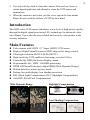
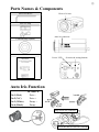
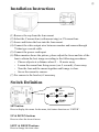
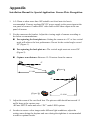
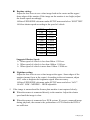
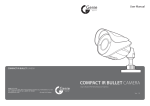
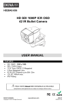
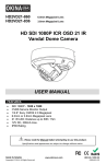
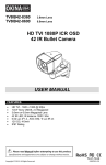
SERVICE MANUAL 1/3” SONY DSP COLOR CCD CAMERA 600TVL O.S.D. WDR SERIES The serial number of this product may be found on the bottom of the unit. You should note the serial number of this unit in the space provided and retain this instruction as a permanent record of your purchase to aid identification in the event of theft. Model No. Serial No. V.4B_W_M ① CAUTION RISK OF ELECTRIC SHOCK DO NOT OPEN CAUTION: TO REDUCE THE RISK OF ELECTRIC SHOCK, DO NOT REMOVE COVER (OR BACK), NO USER SERVICEABLE PARTS INSIDE. REFER SERVICING TO QUALIFIED SERVICE PERSONNEL. The lightning flash with arrowhead symbol, within an equilateral triangle, is interned to alert the user to the presence of uninsulated “dangerous voltage” within the product’s enclosure that may be of sufficient magnitude to constitute a risk of electric shock to persons. The exclamation point within an equilateral triangle is intended to alert the user to the presence of important operating and maintenance (servicing) instructions in the literature accompanying the appliance. ▲ Before attempting to connect this product, please read and keep this manual for future use. Safety Warning 1. Do not open the cover, it may cause electric shock. Ask a qualified service person for maintenance when you encounter any problems. 2. Install the camera away from TV, radio transmitter, magnet, electric motor, transformer, audio speakers because the magnetic fields generated from above devices will distort the video image. 3. Place this camera on a solid base. Install the camera away from stoves or other heat generating devices as the high temperature could cause deformation, discoloration or other damages to the camera. Install the camera at where the temperature range does not exceed -10°C to 50°C (14°F to 122°F) 4. Do not expose and operate the camera in the rain and humid areas. ② 5. Use only soft dry cloth to clean the camera. Also use lens tissue or cotton tipped applicator and ethanol to clean the CCD sensor and camera lens. 6. When the camera is not in use, put the cover cap on the lens mount. Please do not touch the surface of CCD by bare hand. Introduction This OSD series CCD camera introduces a new level of high picture quality through the digital signal processing LSI’s technology for advanced video surveillance. It provides the most reliable and accurate color picture in the security industries. Main Features z z z z z z z z z z z Color camera with SONY 1/3” Super HAD II CCD sensor. Employs Digital Signal Processor (DSP) chip-set for image control. Ultra high resolution 600TVL (B/W 650TVL). High sensitivity CCD enables a clear image even in 0.01Lux. Controlled by OSD (On Screen Display) menu. Programmable AE / AWB / GAMMA processing. 2DNR (2D Noise Reduction), digital WDR (Wide Dynamic Range). Motion detection, mirror, privacy mask. Parking line guide display, lens shading correction. BLC (Back Light Compensation), HLC (Highlight Compensation). Auto DPC (Dead Pixel Compensation). Wide Dynamic Range Highlight Compensation Lens Shading Compensation ③ Parts Names & Components Hex Screwdriver Hole to fix lens Auto Iris Plug Auto iris connector C-Mount Ring (Option) Manual Power LED Selection & setting buttons Auto Iris Function DC DRIVE Pin 1 (Red) Drive - Pin 2 (N.C) Drive + Pin 3 (White) Damp + Pin 4 (Black) Damp Plug in auto iris connector Screw the auto iris lens on CS mount ④ Installation Instructions (1) Remove the cap from the lens mount. (2) Select the C mount lens (with mount ring) or CS mount lens. (3) Screw and fasten the lens into the lens mount. (4) Connect the video output wire between monitor and camera through 75ohm type coaxial cable. (5) Connect the power cord input. (6) When monitor shows the picture, please adjust the focus and iris of the lens to obtain the best image according to the following procedures: ‧ Choose objects at a distance about 5 ~ 10 meter away. ‧ Loosen the mount lens fixing screw (use L wrench), if necessary. ‧ Turn the lens and the mount together until image is clear. ‧ Screw the mount to camera. (7) Fix camera to the bracket, if necessary Switch Definition UP button LEFT button SET button RIGHT button DOWN button SET button Press to display the menu. In the menu, this button functions as “ENTER”. UP & DOWN buttons Press to select the item of menu. LEFT & RIGHT buttons Press to change the item value. ⑤ Menu Operation ‧ Press the SET button to display the menu on screen. ‧ Press the UP or DOWN button to select the item. ‧ The selected item will be highlighted. ‧ Press the LEFT or RIGHT button to change mode. ‧ The ENTER symbol means there is a sub-menu. Press the SET button to enter to the sub-menu. ‧ Select the EXIT item and press the SET button to finish setting. SETUP MENU LENS To select the lens mode depending on the lens used: ‧ MANUAL When manual iris lens is used. ‧ DC When auto iris lens that requires a DC drive signal is used. ‧ VIDEO Not available. EXPOSURE ¾ SHUTTER To change the shutter setting and speed based on the environment. ‧ AUTO After an immobile brightness value is set, the shutter speed will adjust automatically to achieve the value. ‧ FLK Select when flickering occurs on the screen due to an Imbalance between illumination and frequency. Under this mode, the shutter speed is NTSC: 1/100; PAL: 1/120. ‧ Fixed speed adjustable: 1/50; 1/250; 1/500; 1/1000; 1/2000; 1/4000; 1/5000; 1/10000; 1/100000. ¾ BRIGHTNESS Value 0~255 adjustable. ¾ AGC (Auto Gain Control) Enable this function to heighten the brightness signal automatically. ‧ HIGH LOW; MIDDLE adjustable. ‧ OFF To disable this function. ¾ DWDR (Digital Wide Dynamic Range) When there is a very strong backlight behind the object, more than the AGC function can handle, enable this function to achieve a clear image of the background as well as the object. ‧ ON To enable this function. Value 0~63 adjustable. ‧ OFF To disable this function. WHITE BAL. (White Balance) ‧ ATW1 Auto Tracking White Balance. The white balance will adjust continually according to the color temperature of the object. The ⑥ range of color temperature is 2,000°K~9,500°K. ‧ ATW2 Auto Tracking White Balance. The white balance will adjust continually according to the color temperature of the object. The range of color temperature is 2,000°K~10,500°K. ‧ AWCÆSET Auto White Balance Control. Push to set white balance according to the color temperature of the background. ‧ MANUAL The manual adjustment mode enables finer adjustment of ATW. Set the color temperature to MANUAL and then increase or decrease the RED (0~255) and BLUE (0~255) color values while monitoring the color changes on the object. Or, chose the INDOOR; OUTDOOR mode for quick adjustment. BACKLIGHT When there is strong backlight behind the object, enable this function to achieve a clear image of the background as well as the object. ‧ BLC Back Light Compensation. AREA1; AREA2 adjustable. ‧ HLC Hightlight Compensation. ALL DAY; NIGHT ONLY adjustable. ‧ OFF To disable this function. DAY&NIGHT ‧ COLOR Common mode. ‧ AUTO Automatically changes between color mode under bright light environment and B/W mode under low light environment. Set the value of D-N LEVEL (Day to Night 0~216); N-D LEVEL (Night to Day 0~206); D-N DELAY (Day to Night 1~30 SEC); N-D DELAY (Night to Day 1~30 SEC) to define the changing condition and time. ‧ B/W Stay in B/W mode for clear and better visibility image under low light environment. BURST (ON; OFF); IR SMART (ON; OFF); IR LEVEL (HIGH; LOW) adjustable. ‧ EXT Control day & night mode by external device (if connected). DPC (Dead Pixel Correction) Cover the lens then press SET button to delete dead pixel on screen. SPECIAL MENU CAM TITLE (Camera Title) ‧ ON To name the camera title. ‧ OFF Not active. MOTION (Motion Detection) When the object on screen is moving, the camera will detect the changes and display a warning on screen. ‧ ON AREA1~AREA4 adjustable. 0~255 DEGREE adjustable. ‧ OFF Not active. ⑦ PRIVACY (Privacy Zone) Cover the areas you do not wish to appear on screen. ‧ ON AREA1~AREA8 adjustable. 0~15 COLOR adjustable. ‧ OFF To disable this function. PARK. LINE (Parking Line) ‧ ON Parking line guide display on screen. ‧ OFF To disable this function. IMAGE ADJ. ¾ LENS SHAD. (Lens Shading Compensation) ‧ ON Counter lens shading on the four corners of monitor screen. ‧ OFF To disable this function. ¾ 2DNR (2D Noise Reduction) Enable this function to reduce the noise at low light environment. This function enables the camera to use a higher AGC level to electronically enhance the sensitivity of the camera in low light environment (higher AGC, more noise). ‧ ON To enable this function. ‧ OFF To disable this function. ¾ MIRROR ‧ ON ‧ OFF To see mirror image on monitor screen. To disable this function. ¾ FONT COLOR FONT color (0~15); ID&TITLE (0~15) adjustable. ¾ CONTRAST Value 0~255 adjustable. ¾ SHARPNESS Value 0~255 adjustable. ¾ DISPLAY ‧ CRT ‧ LCD ‧ USER PED LEVEL (0~63); COLOR GAIN (0~255) adjustable. GAMMA (0.05~1.00); PED LEVEL (0~63); COLOR GAIN (0~255) adjustable. GAMMA (0.05~1.00); PED LEVEL (0~63); COLOR GAIN (0~255) adjustable. ¾ NEG. IMAGE (Negative Image) ‧ ON To show negative image on monitor screen. ‧ OFF To disable this function. LANGUAGE Supports ENGLISH; 中文 (Simple Chinese). VERSION To show the version of this camera. RESET Select for factory reset. Specification MODEL IR OPTICAL FILTER PICK-UP DEVICE EFFECTIVE PICTURE ELEMENTS (H*V) SIGNAL PROCESSOR RESOLUTION MIN. ILLUMINATION S/N RATIO POWER SUPPLY CONTROL LENS MOUNT AUTO IRIS AUTO ELECTRONIC SHUTTER VIDEO OUTPUT POWER CONSUMPTION OPERATING TEMP. OSD WDR OSD WDR with ICR (True DAY & NIGHT) Built-in anti-aliasing IR-cut filter Built-in anti-aliasing IR-pass (850nm) filter Sony 1/3" Super HAD II High Resolution CCD NTSC: 768*494 PAL: 752*582 D.S.P. (Digital Signal Processor) 600 TV Lines (B/W 650 TV Lines) 0.01Lux / F1.2 More than 52 dB DC12V; AC90~260V Switching Power; DC12V/AC24V Dual Power O.S.D. (On Screen Display) C / CS Mount DC Drive Auto Iris Lens NTSC: 1/60s~1/100,000s (AES ON); 1/60s (AES OFF) PAL: 1/50s~1/110,000s (AES ON); 1/50s (AES OFF) 1 Vp-p Composite Video / 75 ohm Load 3.5W (Max.) -10°C~50°C (14°F~122°F) MENU OPERATION SETUP MENU SPECIAL MENU LENS: MANUAL – DC – VIDEO EXPOSURE: ¾ SHUTTER: AUTO – FLK – 1/50 – 1/250 – 1/500 – 1/1000 – 1/2000 – 1/4000 – 1/5000 – 1/10000 – 1/100000 ¾ BRIGHTNESS: 0~255 ¾ AGC: LOW – MIDDLE – HIGH – OFF ¾ DWDR: ON (0~63) – OFF WHITE BAL.: ATW1 – ATW2 – AWCÆSET – MANUAL: RED (0~255); BLUE (0~255) – INDOOR – OUTDOOR BACKLIGHT: BLC: AREA1; AREA2 – HLC: ALL DAY; NIGHT ONLY – OFF DAY&NIGHT: COLOR – AUTO – B/W – EXT DPC RESET CAM TITLE: ON – OFF MOTION: ON: AREA1~AREA4; DEGREE (0~255) – OFF PRIVACY: ON: AREA1~AREA8; COLOR (0~15) – OFF PARK. LINE: ON – OFF IMAGE ADJ.: ¾ LENS SHAD.: ON – OFF ¾ 2DNR: ON – OFF ¾ MIRROR: ON – OFF ¾ FONT: FONT (0~15); ID&TITLE (0~15) ¾ CONTRAST (0~255) ¾ SHARPNESS (0~255) ¾ DISPLAY: CRT: PED LEVEL (0~63); COLOR GAIN (0~255) LCD: GAMMA (0.05~1.00); PED LEVEL (0~63); COLOR GAIN (0~255) USER: GAMMA (0.05~1.00); PED LEVEL (0~63); COLOR GAIN (0~255) ¾ NEG. IMAGE: ON – OFF LANGUAGE: ENGLISH – S.CHINESE VERSION V.4B_W_M Appendix Installation Manual for Special Application: License Plate Recognition 1. A 5-55mm or other more than 10X suitable vari-focal auto iris lens is recommended. Connect regulated DC12V power supply to the power input at the rear panel of camera. Connect BNC video cable to the video output at the rear panel of camera. 2. Fix the camera on the bracket. Adjust the viewing angle of camera according to the below recommendations: For capturing the front plate no.: Setting the camera at a 15° or less vertical angle will achieve the best performance. Do not let the vertical angle exceed 20° (Figure 1). For capturing the back plate no.: The vertical angle must not exceed 30° (Figure 2). Capture zone distance: Between 15~20 meters from the camera. 0° <20° [Figure 1] 15~20M 0° <30° [Figure 2] 15~20M 3. Adjust the zoom of the vari-focal lens. The picture width should not exceed 1.5 traffic lanes at the capture zone. Æ Enter SETUP menu and select “DC” under LENS options. 4. In order to ensure a clear image under different light conditions, adjust the settings once during the daytime and once during the nighttime is recommended to achieve optimal results. Daytime setting: Adjust the lens focus to see a clear image both at the center and the upper / down edges of the monitor. If the image on the monitor is too bright, adjust the shutter speed accordingly. Æ Enter EXPOSURE sub-menu under SETUP menu and select “SHUTTER”. Æ Select shutter speed according to the speed of vehicle. NTSC PAL 1/60 1/50 1/250 1/250 1/500 1/500 1/1000 1/1000 1/2000 1/2000 1/4000 1/4000 1/5000 1/5000 1/10000 1/10000 1/100000 1/100000 Suggested Shutter Speed: ¾ When speed of vehicle is less than 50km: 1/250 sec. ¾ When speed of vehicle is less than 100km: 1/500 sec. ¾ When speed of vehicle is more than 100km: 1/2000 sec. Nighttime setting: Adjust the lens focus to see a clear image at the upper / down edges of the monitor (means focus at the center). According to the environment, adjust AGC value to heighten the brightness signal when necessary. Æ Enter EXPOSURE sub-menu under SETUP menu and select “AGC”. Æ AGC: LOW – MIDDLE – HIGH adjustable. 5. If the image is smeared and the license plate number is not captured clearly: When the camera is connected directly to the monitor: Adjust the shutter speed until the image is clear. When the camera is connected to a DVR system: If you get a smeared image during playback, the reason is the performance of VGA card in the DVR is not sufficient. V.4B_W_M