1
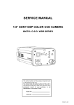
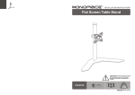
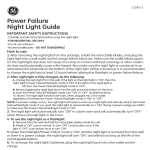
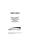
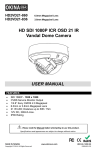
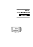
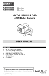
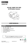
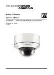
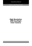
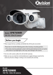
2DNR 3-Axis Gimbal
Vari-focal Vandal Resistant
Dome Camera
8
Mounting Housings to Electrical Junction Boxes
9
10
11
12~24
Fan & Heater (Option)
25
26~27
SERVICE MONITOR &
CONTROL CABLE
FH
Torx Wrench: Length 90mm (1pc)
Dowel: Length 30mm, Thickness 6mm (4pcs)
Assembly Screws: FH M4x14 (4pcs)
- These screws are used to affix flush mount base to surface mount plate.
Mounting Screws:
- These screws are used to mount both surface mount plate or flush mount
base to a sturdy surface. If necessary, use the dowels included.
Pipe Cap Driver:
Service monitor and control cable:
- Monitoring the display screen through portable monitor and adjusting the
OSD menu of the camera externally.
1/3” Sony Super HAD II High-resolution Color CCD
600TVL High-Resolution
2.8 ~ 10.5mm Vari-Focal, DC Auto Iris F1.2 Lens
- Option: 2.8~11mm F1.2, 3.8~9.5mm F1.2
Built-in DNR, OSD function
Back Light or High Light Compensation(BLC/HLC) function
Color & B/W Auto switchable by photocell (Day&Night type)
Auto switching IR LED control by photocell (36pcs-IR LED type)
Easy Adjustment of Focal Length & Focus
Built-in Service Monitor & OSD Control Port
3-Axis Gimbal Bracket
Flush & Surface mount
Fan & Heater available (Option)
Vandal Resistant & Weatherproof Housing (IP-66)
Power: AC24V/DC12V or DC12V
100
152
50
126
50
20
102
32
149
116
1. Bubble
2. Dome Cover Ring
3. Lens
4. Safety Wire
5. Service Monitor Output Port
6. Flush Mount Base
7. Surface Mount Plate
8. Assembly Screws (M4x8)
9. Assembly Screws (FH M4x14)
10. Gimbal-Bracket
11. Mounting Screws (ST4x38)
12. Video/Power Cable
To avoid smear, do not expose the camera
directly to a strong light source such as the
sun or spot light.
FH
Screws, FH M4x14
- All camera models are supplied with service monitor output the
inside units.
If you need to set up OSD menu, use
the service monitor and control cable.
10
Rotation
Rotation
loosen the lever bolt and make necessary
Focus
adjustments.
lever bolt
Loosen Zoom& Focus lever bolt and
Zoom
lever bolt
3. After adjustments, tighten the lever bolts to lock.
ZOOM/FOCUS LEVER DETAIL VIEW
LOCK
UNLOCK
T
T
UNLOCK
LOCK
f=2.8~10.5mm
11
f=2.8~11mm, 3.8~9.5mm
> SET Key: Access to the menu or confirm the setting.
To enter the main menu, press the SET Key once.
> UP/DOWN Key
: Choose the desired sub-menu.
> LEFT/RIGHT Key
: Set up the value of the selected menu.
Used to adjust the desired menu selection, and to move the cursor left or right.
LENS
DC
EXPOSURE
SHUTTER
AUTO,1/60,FLK,1/250,1/500,
1/1000,1/2000,1/4000,1/10000
BRIGHTNESS 0~255
AGC
OFF, LOW, MIDDLE, HIGH
DWDR
ON/OFF
RETURN
RET/END
12
WHITE BAL.
ATW1
ATW2
BACKLIGHT
AWC->SET
AWC->SET (PUSH)
MANUAL
COLOR TEMP.
MANUAL
BLUE
0~255
RED
0~255
RETURN
RET/END
COLOR TEMP.
INDOOR
BLUE
--
RED
--
RETURN
RET/END
COLOR TEMP.
OUTDOOR
BLUE
--
RED
--
RETURN
RET/END
OFF
BLC
HLC
AREA SEL
AREA1/AREA2
AREA STATE
ON/OFF
GAIN
0~255
HEIGHT
0~15
WIDTH
0~15
LEFT/RIGHT
0~15
TOP/BOTTOM
0~15
RETURN
RET/END
LEVEL
0~255
MODE
ALL DAY
NIGHT ONLY
RETURN
13
RET/END
IMAGE ADJ.
LENS SHAD.
ON/OFF
2DNR
ON/OFF
MIRROR
ON/OFF
FONT COLOR FRONT
0~15
ID & TITLE
0~15
RETURN
RET/END
CONTRAST
0~255
SHARPNESS
DISPLAY
0~31
CRT
PED LEVEL(0~63)
COLOR GAIN(0~255)
LCD
RETURN(RET/END)
GAMMA(0.05~1.00)
PED LEVEL(0~63)
COLOR GAIN(0~255)
RETURN(RET/END)
USER
GAMMA(0.05~1.00)
PED LEVEL(0~63)
COLOR GAIN(0~255)
RETURN(RET/END)
SPECIAL
NEG. IMAGE
ON/OFF
RETURN
RET/END
CAM TITLE
ON/OFF
DAY&NIGHT * AURO/COLOR/BW/EXT
MOTION
AREA SEL.
AREA1~AREA4
AREA STATE
ON/OFF
HEIGHT
0~15
WIDTH
0~15
LEFT/LIGHT
0~15
14
SPECIAL
MOTION
PRIVACY
RESET
TOP/BOTTOM
0~15
DEGREE
0~255
VIEW
ON/OFF
RETURN
RET/END
AREA SEL.
AREA1~AREA8
AREA STATE
ON/OFF
HEIGHT
0~15
WIDTH
0~15
LEFT/LIGHT
0~15
TOP/BOTTOM
0~15
COLOR
0~15
RETURN
RET/END
DPC
AUTO DEFECT(64 point)
VERSION
00,00,01
RETURN
RET/END
FACTORY
RESET
RETURN
RET/END
EXIT
DAY&NIGHT * :
Standard type cameras do not support the DAY&NIGHT function.
15
The Setup is used to control and adjust the many features and options
available on your camera. Read thoroughly before making any adjustments.
Note: These options have been pre-configured at the factory for optimal
performance.
SETUP
LENS
EXPOSURE
WHITE BAL.
BACKLIGHT
IMAGE ADJ.
SPECIAL
RESET
EXIT
DC
ATW1
BLC
LENS
This is always set on DC and cannot be changed.
EXPOSURE
SHUTTER: (AUTO, FLK, 1/60(1/50) ~ 1/100,000)
The SHUTTER speed can be selected manually to user preference.
Typically, to track fast moving objects across your screen, a faster shutter
speed is used. The shutter speed of 1/60(NTSC), or 1/50(PAL) seconds are
recommended.
16
> AUTO: Select the AUTO mode for automatic adjustment of the shutters.
It will slow down or speed up depending on the environment.
> FLK: Select the FLK mode if the screen flickers due to differences in light
and electric frequencies.
BRIGHTNESS: 0~255
The BRIGHTNESS can be adjusted by opening and closing of the Iris aperture.
User may fine-tune the screen to their preferred brightness. The brightness
ranges from 0~255.(0 being the darkest and 255 being the brightest possible)
AGC (Automatic Gain Control) : OFF, LOW, MIDDLE, HIGH
This function is used to amplify the video signal when it falls below the set
parameter. As the AGC level increase, the overall screen gets brighter but the
level of noise is increased.
Note: The AGC feature cannot be modified while Day&Night mode is set to
AUTO. By factory default, AGC is automatically set on “MIDDLE”.
DWDR (Digital Wide Dynamic Range): ON, OFF
Wide Dynamic Range works to correct excessive light within the frame to
produce a usable image.
It works by calculating the ratio between the brightest and darkest values of
the picture and determines the balanced medium.
RETURN: RET, END
Selects “RET” to go back to the main menu. Select “END” to save and exit.
WHITE BAL.
This function is used to control the while balance under different lighting
conditions. Adjusting this setting calibrate the camera for correct color rendering.
The factory default of ‘ATW1’ is recommended for optimal performance.
17
ATW1 (Auto Tracing White Balance mode 1):
Select the ATW1 mode to automatically adjust the color temperature according
to its ambient condition. (2,300~9,500K)
ATW2:
Select the ATW2 mode if the color temperature of the light source is between
2,000~11,000K.
AWC (Auto White Balance Control):
Use the AWC function to correctly calibrate the white balance of the camera.
While in this mode, press the SET key while placing a white sheet of paper in
front of the camera. Repeat this procedure if there is a change in location or
light source.
MANUAL: INDOOR, OUTDOOR, MANUAL
If you press the SET key, you can adjust color temperature manually.
The Blue and Red values can be adjusted independently only in the Manual
mode.
- INDOOR: Sets the color temperature properly for the indoor condition.
- OUTDOOR: Sets the color temperature properly for the outdoor condition.
- MANUAL: Adjust the strength of the red color or the blue color manually.
BACKLIGHT
This function is used to compensate for exposure problem associated with
extremly bright backgrounds causing the subjects to bloom or silhouette.
BLC (Back Light Compensation):
The BLC divides the frame and calculates exposure levels of each zone to
counterbalance excessive background light in order to distinguish the subject
in the foreground. There are 2 white boxes representing the areas affected
by BLC. Each boxes can be individually adjusted to user preference.
18
> AREA SEL. (AREA1~AREA2): Choose one of two pre-defined boxes to
adjust its size or location.
> AREA STATE (ON, OFF): Select a box active or inactive for BLC.
> HEIGHT, WIDTH: Adjust the height or width of the area.
> LEFT/RIGHT, TOP/BOTTOM: Changes the location of the defined area.
> RETURN: Select RET to save and exit, and to go back to the MAIN MENU.
HLC (High Light Compensation):
The HLC masks out excessively bright areas within the frame and compensates
the rest accordingly.
> LEVEL(0~255): Choose the intensity of the HLC.
> MODE(ALL DAY, NIGHT ONLY): Choose the preferred mode. ‘ALL DAY’
keeps the HLC mode on day or night, and ‘NIGHT ONLY’ only during night
mode.
IMAGE ADJ.
LENS SHAD. : 0~255
Convex shape of the lens causes the light to enter the camera unevenly and
typically makes the center of the screen brighter than the rest. Adjusting this
setting will compensate for this undesirable effect and make the screen more
even.
2DNR (Digital Noise Reduction) : ON, OFF
The DNR improves picture quality by filtering out signal noise associated with
night-time recording. DNR compares pictures from a frame with the one previous
and removes noise grains not present before.
MIRROR : ON, OFF
This function is used to inverse the pictures coming from the camera.
19
FRONT COLOR
Change the OSD menu front color to user preference when there isn’t enough
contrast between the picture and the menu to distinguish the letters.
> FRONT: Choose from the 15 available colors.
> ID&TITLE: Choose from the 15 available colors.
CONTRAST: 0~255
Adjust the contrast of image, the difference between light and dark areas on
the screen.
SHARPNESS: 0~31
Adjust the display image sharpness.
DISPLAY: CRT, LCD, USER
Selecting the correct type of viewing monitor will ensure the most optimal
picture.
NEG. IMAGE: ON, OFF
This function reverses the pictures to view in inverse.
Light to dark and vice versa.
RETURN
Selects “RET” to save and exit, and to go back to the MAIN MENU.
SPECIAL
This function is used to control the CAMERA TITLE, DAY&NIGHT, MOTION,
PRIVACY, DPC, and display the VERSION number of the camera.
CAM TITLE: ON, OFF
The CAMERA TITLE is used to assign a number or a custom title to easily
identify between the many cameras that may be connected to your DVR.
20
Programing the Camera ID:
1. Press the LEFT or RIGHT key to turn On the Camera Tiltle mode.
2. While Camera ID function is On, press the SET key to enter the sub-menu.
3. Using the directional navigation keys, choose from alphabetical letters and
numbers to create a 15-digit Camera ID.
4. Move the cursor to POS and press the SET key.
The Camera ID will appear on the bottom center.
5. Using the directional navigation keys, change the position of the Camera
Title to the desired location.
6. Move the cursor to END, then press the SET key to save and exit.
DAY & NIGHT : AUTO, COLOR, B/W, EXT
This funciton is used to control the color setting during daytime and nighttime operation.
Standard Type Camera
> Not available
: Standard type cameras do not support the DAY&NIGHT function.
Day&Night Type Camera
> AUTO, COLOR, B/W, EXT
: Day&Night type cameras have the inner photocell. This function is an
auto switching between DAY and NIGHT mode using the detected
brightness level by photocell.
IR-LED Type Camera
> AUTO, COLOR, B/W, EXT
: Choose from the AUTO, COLOR, B/W, EXT modes
21
> AUTO: The Color mode is operated during daytime and automatically
converts to B/W mode in the absence of light during night-time.
AGC cannot be modified in this mode.
D => N Level This level determines the level of darkness before switching from Day mode
to Night mode.
D => N Delay This function is used to set the delay between switching of the modes.
If the delay has been set to ‘3’, the camera will observe darkness for at least
3 seconds before switching to Night mode.
N => D Level - Opposite of D => N Level.
N => D Delay - See above D => N Delay.
> COLOR: The camera is always in Color mode.
> B/W: The camera is always in B/W mode.
BURST OFF - This function smooths out noise in BW mode.
BURST ON - This function makes the transition between switching of the
modes smoother when Color turns to BW.
IR SMART (ON/OFF) - This function detects too much IR reflection and
automatically compensates for the over exposure. Specific area can be
defined by adjusting the location and size of the detection grid.
IR LEVEL (HIGH/LOW) - This function is used to higher or lower the IR LED
intensity.
> EXT: This feature is not supported.
MOTION : ON, OFF
This function is used to detect motion in the monitored area.
The “Running Man” icon will be displayed on the bottom left corner once
motion has been detected. There are 4 pre-defined white boxes representing
the areas monitored for motion. Each boxes can be individually adjusted to
user preference.
22
> AREA SEL. (AREA1~4): Choose one of four pre-defined boxes to adjust its
size or location.
> AREA STATE (ON,OFF): Select a box active or inactive for motion detection.
> HEIGHT, WIDTH: Adjust the height or width of the area.
> LEFT/RIGHT, TOP/BOTTOM: Changes the location of the defined area.
> DEGREES (0~255): Increases or decreases the sensitivity of the selected
area. Increasing the number decreases sensitivity.
> VIEW (ON,OFF): Turns the “Running Man” indication On or Off.
> RETURN: Select RET to save and exit, and to go back to the MAIN MENU.
PRIVACY : ON, OFF
This function is used to mask specific areas within the frame of the camera
to be concealed. There are total of 8 different colored boxes representing the
masked areas. Each boxes can be individually adjusted to user preference.
> AREA SEL. (AREA1~8): Choose one of 8 colored boxes to adjust its size or
location.
> AREA STATE (ON,OFF): Select a box active or inactive for privacy masking.
> HEIGHT, WIDTH: Adjust the height or width of the area.
> LEFT/RIGHT, TOP/BOTTOM: Changes the location of the defined area.
> COLOR (1~15): Choose one of 15 colors for the masked area.
> VIEW (ON,OFF): Turns the “Running Man” indication On or Off.
> RETURN: Select RET to save and exit, and to go back to the MAIN MENU.
DPC (Dead Pixel Compensation)
This function is used to compensate for the dead pixel areas of the screen.
When a defective pixel is detected, a neighboring pixel information is used
to determine the approximate pixel data and is replaced. The DPC is capable
of compensating up to 64 points of dead pixels.
VERSION
The camera firmware version is displayed.
23
RETURN
Selects “RET” to save and exit, and to go back to the MAIN MENU.
RESET
This function is used to reset all camera settings to the factory default settings.
EXIT
Choose EXIT to save and exit from the menu mode.
24
- For Fan & Heater operation, AC24V power input is required.
- UTP models and DC12V operation models are not supported
Fan & Heater function.
25
Common Specification
1/3” Interline Transfer Type Color CCD (Sony)
1/60sec, FLK,
Auto(1/60 ~ 1/100,000sec)
1/50sec, FLK,
Auto(1/50 ~ 1/100,000)sec
More than 48dB (AGC Off)
ATW1 / ATW2 / AWC / Manual
(ATW1: 2,300 ~9,500°K, ATW2: 2,000 ~11,000°K)
On/Off
DWDR
On/Off
152mm
26
126mm
Standard Type
600TVL
0.2Lux @F1.2
f = 2.8~10.5mm Vari-Focal, DC Auto Iris F1.2 Lens
(Option: 2.8~11mm F1.2, 3.8~9.5mm F1.2)
DC12V
Max.: 100mA/DC12V
AC24V/DC12V Max.: 4.8VA/AC24V, 150mA/DC12V
Day & Night Type
600TVL(Color), 650TVL(B/W)
Day&Night Functionality
ICR type on EXT(photocell)
0.2Lux (Color), 0.02Lux (B/W) @F1.2
f = 2.8~10.5mm Vari-Focal, DC Auto Iris F1.2 D/N Lens
(Option: 2.8~11mm F1.2, 3.8~9.5mm F1.2)
DC12V
Max.:110mA/DC12V
AC24V/DC12V Max.:5.1VA/AC24V, 160mA/DC12V
IR-LED Type
600TVL(Color), 650TVL(B/W)
ICR type on AUTO(photocell)
Day&Night Functionality
0 Lux (IR-LED On)
f = 2.8~10.5mm Vari-Focal, DC Auto Iris F1.2 D/N Lens
(Option: 2.8~11mm F1.2, 3.8~9.5mm F1.2)
DC12V
Max.:390mA/DC12V(IR-LED On)
AC24V/DC12V Max.:10.5VA/AC24V, 490mA/DC12V(IR-LED On)
27
2DNR 3-Axis Gimbal
Vari-focal Vandal Resistant Dome Camera
ML11052V6400A