1
CONNECT SYSTEMS INCORPORATED
1802 Eastman Ave., Suite 116
Ventura, Ca. 93003
Phone (805) 642-7184
Fax (805) 642-7271
FLEX SERIES UNIVERSAL CONTROLLER
VOICE ALARM SYSTEM
User’s Instruction Manual
Made in U.S.A.
Copyright 2003 By Connect Systems Inc.
Connect Systems Inc. - Flex Series Universal Controller
1
CONNECT SYSTEMS INCORPORATED
1802 Eastman Ave., Suite 116
Ventura, Ca. 93003
Phone (805) 642-7184
Fax (805) 642-7271
FLEX SERIES UNIVERSAL CONTROLLER
VOICE ALARM SYSTEM
User’s Instruction Manual
Version 1.01
Made in U.S.A.
Copyright 2003 By Connect Systems Inc.
Connect Systems Inc. - Flex Series Universal Controller
2
TABLE OF CONTENTS
TABLE OF CONTENTS
General Description
Connections
Adjustments
Jumper Straps
Programming Information
Different Programming Areas
Programming Fields
Global Parameters
Voice Alarm Operation
General Hardware Description
Warranty
FCC Notice to users
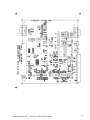
Parts Location
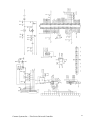
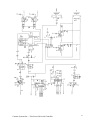
Schematic Diagrams
Part List
3
4
6
8
9
11
14
20
25
26
29
30
31
32
36
----------------------------------------------------------GENERAL DESCRIPTION
The FLEX Series Universal Controller SIMPLEX VOICE ALARM SYSTEM by
Connect Systems Inc. is an economical controller capable of
repeating transmitting a voice message when an alarm is received.
To accommodate the many programmable features, the system allows
the user to program the system via a telephone plugged in the back
of the unit, through the telephone line, over the air, or through
a computer.
Powerful built in standard features make the FLEX Series Universal
Controller VOICE ALARM SYSTEM the best deal going in VOICE ALARM
SYSTEMS today.
Connect Systems Inc. - Flex Series Universal Controller
3
THE CONNECTIONS
RX AUDIO
For the products detecting CTCSS, DCS, or LTR, or
products that use the internal squelch, the RX AUDIO
must be connected to the discriminator of the radio. For
all other products the RX AUDIO can be connected to the
discriminator, high side of the volume control, or the
speaker.
TX AUDIO
For products that generate CTCSS, DCS, or LTR, the TX
AUDIO must be connected directly to the modulator of the
transmitter. For LTR and DCS, the modulator must be true
FM. For CTCSS the modulator can be phase modulated or FM
modulated. For all other applications, connections to
the high side of the microphone is acceptable.
It
should
be
noted
that
in
most
communication
controllers there is a separate line for voice audio and
a separate line for the CTCSS, DCS, or LTR signals. This
is because to combine the two the controller has to have
a limiter on the voice line to prevent over modulation
and other undesirable side effects. The Flex Series
Controllers has a built in limiter thereby not requiring
separate lines.
PTT
The PTT normally hooks to the PTT of the transmitter. If
you are using a Hand Held with the PTT sharing a common
connection with the transmit audio, then attach a
resistor with a value between 2.4K and 4.7K from the PTT
to the TX Audio and attach the TX audio line to the
center conductor of the microphone cable. In most
product that use the PTT, the AUX relay can also be used
as a PTT connection. This has the advantage of allowing
positive keying or other situations where the normal
open collector PTT does not work.
COS
Connect to a point that has a good voltage swing when
the squelch is opened/closed. The best point to connect
is to the collector of the transistor that controls the
busy light (if the receiver has one). Otherwise you may
connect to the squelch control voltage. The minimum
voltage for the COS is about .4 volts and the Maximum
voltage is the supply voltage.
Some radios have that point coming out the back of the
radio. It sometimes goes under the name of squelch
detect, sq det, or COR. In some case a pull up or pull
down resistor is necessary.
The polarity and other parameters associated with the
COS is contained within the programming parameters
Connect Systems Inc. - Flex Series Universal Controller
4
described later. It should be noted that in most cases,
the COS can be replaced with the internal squelch.
SENSE
This point is used as an auxiliary input for specialized
purposes in certain products. As an example, this input
may be used to detect the presence of a CTCSS/DCS signal
in an LTR system. The minimum voltage for the sense
input is about .4 volts and the Maximum voltage is the
supply voltage.
The polarity and other parameters associated with the
SENSE is contained within the programming parameters if
used.
AUX RELAY These two points connects to the center contact and
normally open contact of the relay. The use if any
depends upon the product.
+12 VDC
Connect to a source of 12 volts to 15 volts DC. The Flex
Series Controllers are reverse polarity protected, so a
polarity mistake will not damage the product. Connect
the return lead to ground. The two grounds in the system
are connected to each other.
Connect Systems Inc. - Flex Series Universal Controller
5
ADJUSTMENTS
P1 HYB BAL
The Hybrid Balance control is used to null out the
mobile return audio in full duplex mode. The
alignment must take place on one of the phone lines
the Flex Series controller will be serving. (This
alignment can not be done at the shop prior to
delivery to the site.)
Have a mobile place a call through the Flex Series
Controller. The party answering the called phone
should leave the phone off hook during the
alignment procedure.
Monitor the transmitter output with a service
monitor or connect an oscilloscope to the "TX
OUTPUT" terminal on the rear of the Flex Series
Controller. Place all four Dip switches in the off
position.
Have the mobile simultaneously press digits 3 and 6
on his touch tone keypad. This will result in the
transmission of a single 1477 Hz tone.
Adjust the "HYB BAL" Potentiometer to produce the
least audio output. Try all possible dip position
combinations and null each time. The combination
which gives the minimum output is the correct
position to use.
Changes made within the telephone company or
rerouting of telephone lines could occasionally
require re-adjustment of the hybrid.
P2 Not Used
P3 Tel Vox
Used for detection of call progress tones and
sensitivity to voice in Vox operated applications.
Turning
the
pot
clockwise
increases
its
sensitivity.
P4 Preamp
The preamp control is used to match the audio level
from your receiver to the Flex Series controller.
To adjust, a signal containing 100 Hz CTCSS with
about 600 Hz deviation should be applied to the
receiver. Adjust the preamp control until a level
of 3 volts peak to peak is observed at test point
6. If an oscilloscope is not available, read 1 volt
RMS using a VOM.
P5 RX VOX
Used in VOX mode only. Sets RX audio triggering
sensitivity. Should be fully clockwise in VOX
Connect Systems Inc. - Flex Series Universal Controller
6
simplex applications. Reduce setting when used
through repeaters if land line cannot respond to
mobile during hang time due to noise or tone on the
repeater carrier.
P6 AUDIO OUT
Adjust the maximum level going to the transmitter.
When turned fully clockwise, an output voltage of
about five volts peak to peak is obtained. In most
case the output level can also be set in the
programming mode.
P7 CONTRAST
Sets the contrast of the LCD. Adjust to what is
most pleasing to the individual.
P8 SQUELCH
Advance clockwise to a point just beyond where the
front panel display "Rx" message disappears. Not
all products will display the Rx message.
Connect Systems Inc. - Flex Series Universal Controller
7
JUMPER STRAP OPTIONS
JP1
Line In Use Detector. When inserted, enables line
in use detection. That allows the system to detect
if another phone in parallel with the controller is
off hook. Will only work with a phone system where
the nominal on hook voltage is about 48 volts.
JP2
Preamp Gain. With no jumper installed, gain is 100.
With the jumper connected to the bottom two pins,
the gain is about 10 with a .0047 uF capacitor
giving 3 db cutoff of xxx Hz. With the jumper
connect to the two pins, the gain is about 10 with
a .047 uF capacitor giving a 3 db cutoff of
xxx
Hz.
JP3
JP4
JP5
JP6
JP7
JP8
JP9
JP10
TO
TO
TO
TO
TO
TO
TO
TO
JP11
JP12
JP13
JP14
NOT
NOT
NOT
NOT
JP15
The terminating resistor when used for
communication. Only use once per system.
JP16
When inserted, allows the TX Audio output to be DC
coupled.
BE
BE
BE
BE
BE
BE
BE
BE
DETERMINED
DETERMINED
DETERMINED
DETERMINED
DETERMINED
DETERMINED
DETERMINED
DETERMINED
USED
USED
USED
USED
Connect Systems Inc. - Flex Series Universal Controller
RS485
8
PROGRAMMING INFORMATION
This section on programming shows the different programming fields
that are available across the many different FLEX SERIES UNIVERSAL
CONTROLLER product lines. Not all these fields will be used in a
particular product.
This paging terminal can be programmed four different ways...
Locally, remotely over the air, remotely from any touch tone
phone, or through a computer.
Local Programming: Simply plug any DTMF telephone set into the
rear panel RJ-11 jack labeled "PROG". This allows the telephone
keypad to act as a programming keyboard. The front panel display
will show either the keystrokes or the results of the keystrokes.
DTMF Over the Air Programming: The paging terminal can be
programmed over the air from any DTMF equipped radio. A DTMF
sequence is transponded in response to each command you enter and
is used to display the results of your programming on our CD-2 or
a special version of the Flex Series Controller.
Remote Dial Up Telephone Programming: Occasionally the paging
terminal will be located out of radio range and over the air
programming will not be possible. Simply dial up the paging
terminal to do the programming. You can perform all the
programming functions remotely that you can do locally. If the
programming sequence is accepted, a DTMF sequence is transponded
in response to each command you enter and is used to display the
results on a special version of the Flex Series Controller. If the
command entered is invalid, three beeps will be generated to tell
the user a mistake has been made.
Computer Programming: This self contained program operating in the
windows environment will allow the user to easily make changes to
the characteristics of the paging terminal. This program is not
expected to be released till something next year. This programming
can be accomplished by using a laptop or other computer and
plugging into the front panel plug or by attaching a modem into
the back panel plug. If a modem is used, the unit can be
programmed remotely.
To Enter and Exit Programming Mode: To enter the programming mode,
you must enter the programming mode access code. The access code
consist of six digits plus two leading pound "##" characters and a
trailing pound character. The factory default programming access
code is 123456. The programming access code is always six digits
in length. Therefore the code to get into the programming mode is
##123456#. This code will be valid until you have changed the
Programming Mode Access Code in the GLOBAL programming area.
Connect Systems Inc. - Flex Series Universal Controller
9
When programming is completed, send ##### to exit the programming
mode. If you forget, the Paging terminal is designed is designed
to self exit a few minutes after the last DTMF command.
Command Syntax: When programming, you will enter a programming
sequence such as *0000#03#1#. All commands start with a "*" and
end with a "#". There may be one or more additional "#" to act as
a delimiter between fields.
Leading zeros: Data fields require that you enter the precise
number of digits specified. Numbers that have fewer digits than
the field requires can use leading zeros.
Resetting your position: If you are distracted or have a lapse and
forget where you are in the middle of a command sequence, simply
send * three times (***) and start the sequence over again.
Displaying the field: All the fields can be displayed by the
command *nnnn#nn*. The data followed by the # key is replaced by a
single star. If system is being programmed by a telephone plugged
into the back of the unit, the system will display the results on
the internal LCD display. If the system is being programmed
remotely by DTMF over the radio, then the DTMF string representing
the field will be sent back over the radio. If the system is being
programmed remotely by DTMF over the telephone, then the DTMF
string representing the field will be sent back over the
telephone. If the system is being programmed by a computer, then
the results will be sent back over the RS232 connector located in
the from and the back of the unit.
Different Areas: The programming of the system can be broken up
into different areas. The first area which all products have is
called the “Global Programming Area”. Depending on the product,
different areas may be used such as the “Speed Calling Area” or
the “Speed Dialing Area.” The details will be described below.
Gang Programming: Certain areas will allow gang programming. This
is to allow an entire set of users to be programmed at once with
the same value instead of having to set everybody individually. As
an example, gang programming allows all CTCSS users to be turned
on or be turned off. The details will be discussed in the various
programming areas described below.
Connect Systems Inc. - Flex Series Universal Controller
10
DIFFERENT PROGRAMMING AREAS
GLOBAL PROGRAMMING AREA
The global programming area is used to program parameters that is
common to the entire product. All Global Programming commands
start with *0000#. An example is *0000#01#J#
CTCSS PROGRAMMING AREA
The CTCSS programming area is used to program parameters where the
CTCSS tone is of importance. As an example, the command
*1067#04#1# is used to turn on user with a tone of 67 hertz.
The general form of this area is *1nnn#... where the 1 indicates
the area is CTCSS and the nnn corresponds to a valid CTCSS number.
If the nnn has a value of 999, then gang programming is used and
the 51 different CTCSS users will have the same value programmed.
As an example, if you want to turn off all the CTCSS users, use
the command *1999#04#0#. The 1 indicates it’s a CTCSS field, the
999 indicates it’s a gang programming command, the 04 indicates
its an enable/disable user field, and the 0 indicates the user
should be disabled.
DCS PROGRAMMING AREA
The DCS programming area is used to program parameters where the
DCS code is of importance. As an example, the command *2023#04#1#
is used to turn on user with a code of 023.
The
the
the
112
general form of this area is *2nnn#... where the 2 indicates
area is DCS and the nnn corresponds to a valid DCS number. If
nnn has a value of 999, then gang programming is used and the
different DCS users will have the same value programmed.
As an example, if you want to turn off all the DCS users, use the
command *2999#04#0#. The 2 indicates it’s a DCS field, the 999
indicates it’s a gang programming command, the 04 indicates its an
enable/disable user field, and the 0 indicates the user should be
disabled.
LTR PROGRAMMING AREA
The LTR programming area is used to program parameters where the
LTR ID number and repeater number is of importance. As an example,
the command *3015#246#04#1# is used to turn on user with a
repeater number of 15 and a ID number of 246.
The general form of this area is *30nn#iii#... where the 30
indicates the area is LTR and the nn corresponds to a valid
repeater number and iii is the ID number.
Connect Systems Inc. - Flex Series Universal Controller
11
A valid repeater number has to be between 01 and 20 and a valid ID
number has to be between 001 and 250. Leading zeros must be used
for the repeater number and optionally for the ID number.
If the iii has a value of 999, then gang programming is used and
the 250 different ID numbers for the repeater selected will have
the same value programmed.
SPEED DIAL NUMBER AREA
The speed dial number area is used to program parameters relating
to speed dialing. As an example, the speed dial number. In a
normal phone patch operation, only the speed dial number is used.
However, if wide area networking is desirable, then other
parameters may be necessary.
The general form of this area is *40nn#... where the 40 indicates
the area is speed dialing and the nn corresponds to the speed dial
number position in memory. As an example, 4000 would indicate the
first speed dial number position and 4010 would indicate the
eleventh speed dial number position. If the 40nn is replaced by
4999, then gang programming is used and all 100 different speed
dial number positions will have the same value programmed.
SPEED CALL NUMBER AREA
The speed call number area is used to program parameters relating
to paging. Typically, the only parameter in the speed call number
is the paging number. This allows a user to enter a number from
000 to 999 and the paging corresponding to that user will be
generated. See pager number fields below for a more detailed
description.
The general form of this area is *50nn#... where the 50 indicates
the area is speed call and the nn corresponds to the speed call
number position. As an example, 5000 would indicate the first
speed call number position and 5010 would indicate the eleventh
speed call number position. If the 50nn is replaced by 5999, then
gang programming is used and all 100 different speed call number
positions will have the same value programmed.
PUSH TO CONNECT USERS AREA
The push to connect users area is used to automatically connect
different sites in a wide area network. This will be able to be
used in conventional as well as LTR controllers.
The general form of this area is *60nn#... where the 60 indicate
the area is for push to connect users and the nn corresponds to
the push to connect users position. As an example, 6000 would
Connect Systems Inc. - Flex Series Universal Controller
12
indicate the first push to connect users position and 6010 would
indicate the eleventh push to connect users position. If the 60nn
is replaced by 6999, then gang programming is used and all 100
different push to connect users positions will have the same value
programmed.
VOICE PROMPT AREA
The voice prompt area is used to enter a voice message. This area
is active in all products but not all products use the voice
prompt capability.
For recording, the format used is *7000#n#0#. The value n
corresponds to one of the eight voice memory locations whose
maximum record time is as follows:
N
Maximum Record Time
0
1
2
3
4
5
6
7
9 seconds
9 seconds
9 seconds
9 seconds
9 seconds
25 seconds
25 seconds
25 seconds
The total record time for this product is two minutes.
To play back, use the command *7000#n*
When recording, the system will stop recording either when the
maximum time has expired of the user enters any DTMF key.
Connect Systems Inc. - Flex Series Universal Controller
13
PROGRAMMING FIELDS THAT HAVE TWO POSSIBILITIES
If the field is in the form of *nnnn#nn#J# such as the TELCO
PROGRAMMING field which is *0000#01#J#, then the user must enter
the value of 0 or 1 for the field. Any other number will be
rejected. In most cases, J = 0 means disable the function and J =
1 means enable the function.
PROGRAMMING FIELDS THAT REQUIRE A STRING OF NUMBERS
If the field is in the form of *nnnn#nn#N..NN# sucb as the
PROGRAMMING MODE ACCESS CODE field which is *0000#05#NNNNNN#, then
the user must enter in a number for each of the characters. Some
fields require all the numbers to be entered and some fields may
only require one or more characters to be entered.
PROGRAMMING FIELDS THAT REQUIRE A VALUE
If the field is in the form of *nnnn#nn#MMM# such as the TURN ON
DELAY field which is *0000#08#MM# or the DTMF TELCO LEVEL field
which is *0000#11#MMM#, then the user must enter anywhere from one
to three characters, depending on the field and the value must be
in the range specified. Some fields allow a range of values and
also the value of zero. There is no need for leading zeros.
PROGRAMMING FIELDS THAT EXPECT AN LTR USER
If the field is in the form of *nnnn#nn#RRIII#, then the system is
expecting a valid LTR number. The first two digits is the repeater
number and must be between 01 and 20. The next three digits is the
ID number and must be between 001 and 250. Leading zeros must be
entered.
Connect Systems Inc. - Flex Series Universal Controller
14
PROGRAMMING FIELDS THAT EXPECT A PAGER NUMBER
When applicable, this system supports two tone, five six tone,
CTCSS, DCS, LTR, and DTMF paging. A paging field is a variable
length numeric field where the first three characters is the user
paging number, the next four characters are the CTCSS/DCS number
if used, and the rest of the characters are the paging format as
shown below:
UUU
UUU
UUU
UUU
UUU
UUU
UUU
UUU
UUU
UUU
CCCC
CCCC
CCCC
CCCC
CCCC
CCCC
CCCC
CCCC
0000
0000
0
5
1
6
2
7
3
8
4
9
R
R
GT GT
GT GT
TTT
TTT
D...D
D...D
RR III
RR III
CTCSS/DCS
CTCSS/DCS
TWO TONE
TWO TONE
FIVE/SIX TONE
FIVE/SIX TONE
DTMF
DTMF
LTR
LTR
Signaling
Signaling
Signaling
Signaling
Signaling
Signaling
Signaling
Signaling
Signaling
Signaling
only
+ one
only
+ one
only
+ one
only
+ one
only
+ one
way voice
way voice
way voice
way voice
way voice
UUU can be any three digit number between 000 and 999 and is the
number the user will enter when they want to page someone.
CCCC is the CTCSS or DCS number. If the number is a CTCSS number,
then the first digit is a 1 and the next three numbers are any
valid CTCSS number shown in a table below. If the number is a DCS,
then the first digit is a 2 and the next three numbers are any
valid DCS number shown in a table below. If the value is 0000,
then the CTCSS/DCS tone is not used.
The next digit is between 0 and 9 and represents the type of
paging format to be used as shown in the table above.
Connect Systems Inc. - Flex Series Universal Controller
15
PROGRAMMING FIELDS THAT EXPECT A TELEPHONE NUMBER
If the field is in the form of *nnnn#nn#tt...t#, then the system
is expecting a telephone number. Telephone numbers can have the
following numbers and symbols:
0
1
2
3
4
5
6
7
8
9
*
#
A
B
C
D
W
+
(
)
The “W” key is used for wait for dial tone. The “+” key is used
for delay 3 seconds, and the “(“ and “)” keys are used to delimit
the telephone number to make it easier to read and has no effect
on the dialing.
If you use a standard telephone keypad, the numbers and symbols
are derived as follows:
0
1
2
3
4
5
6
7
8
9
*
#
A
B
C
D
W
+
(
)
press
press
press
press
press
press
press
press
press
press
press
press
press
press
press
press
press
press
press
press
the
the
the
the
the
the
the
the
the
the
the
the
the
the
the
the
the
the
the
the
0
1
2
3
4
5
6
7
8
9
1
2
3
4
5
6
7
8
9
0
key
key
key
key
key
key
key
key
key
key
key
key
key
key
key
key
key
key
key
key
for
for
for
for
for
for
for
for
for
for
at
at
at
at
at
at
at
at
at
at
least
least
least
least
least
least
least
least
least
least
3
3
3
3
3
3
3
3
3
3
seconds
seconds
seconds
seconds
seconds
seconds
seconds
seconds
seconds
seconds
If you have a keypad with the letters A – D, then those keys will
generate A – D no matter how long or how short you hold down the
key. The keys “*” and “#” will act for as control functions no
matter how long or short you hold down the keys.
A- D will generate DTMF tones A – D.
Connect Systems Inc. - Flex Series Universal Controller
16
PROGRAMMING FIELDS THAT REQUIRE AN ALPHNUMERIC STRING
Certain fields such as fields that require the user to enter in
CWID characters or names require letters and numbers. Being that
the telephone has only 10 numbers, a method has to be used to
accommodate all the letters, special characters, and numbers with
only ten numeric keys. This is accomplished by pressing two
numeric keys for each letter. As the user enters the second key,
the display will show the equivalent letter, special character, or
number. The table to accomplish this is shown below.
CHAR VALUE
CHAR VALUE
CHAR VALUE
CHAR VALUE
|-------------------------------------------------------|
| A 00
| Z
25
| y
50
| 75
|
| B 01
| a
26
| z
51
| +
76
|
| C 02
| b
27
| 0
52
| =
77
|
| D 03
| c
28
| 1
53
| {
78
|
| E 04
| d
29
| 2
54
| }
79
|
| F 05
| e
30
| 3
55
| [
80
|
| G 06
| f
31
| 4
56
| ]
81
|
| H 07
| g
32
| 5
57
| |
82
|
| I 08
| h
33
| 6
58
| ;
83
|
| J 09
| i
34
| 7
59
| :
84
|
| K 10
| j
35
| 8
60
| <
85
|
| L 11
| k
36
| 9
61
| >
86
|
| M 12
| l
37
| `
62
| ,
87
|
| N 13
| m
38
| ~
63
| .
88
|
| O 14
| n
39
| !
64
| ?
89
|
| P 14
| o
40
| @
65
| /
90
|
| Q 16
| p
41
| #
66
| sp
91
|
| R 17
| q
42
| $
67
| sp
92
|
| S 18
| r
43
| %
68
| sp
93
|
| T 19
| s
44
| ^
69
| sp
94
|
| U 20
| t
45
| &
70
| sp
95
|
| V 21
| u
46
| *
71
| sp
96
|
| W 22
| v
47
| (
72
| sp
97
|
| X 23
| w
48
| )
73
| sp
98
|
| Y 24
| x
49
| _
74
| sp
99
|
-------------------------------------------------------
Connect Systems Inc. - Flex Series Universal Controller
17
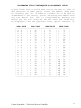
Certain field require the user to enter a CTCSS or DCS number. The
allowable values for that type of field is shows below.
---------------------------------------|
CTCSS ALLOWABLE ENTRIES
|
---------------------------------------|
630
|
114
|
179
|
|
670
|
118
|
183
|
|
694
|
123
|
186
|
|
719
|
127
|
189
|
|
744
|
131
|
192
|
|
770
|
136
|
196
|
|
797
|
141
|
199
|
|
825
|
146
|
203
|
|
854
|
151
|
206
|
|
885
|
156
|
210
|
|
915
|
159
|
218
|
|
948
|
162
|
225
|
|
974
|
165
|
229
|
|
100
|
167
|
233
|
|
103
|
171
|
241
|
|
107
|
173
|
250
|
|
110
|
177
|
254
|
---------------------------------------------------------------------------------------|
DCS ALLOWABLE ENTRIES
|
------------------------------------------------| 006 | 051 | 132 | 214 | 266 | 365 | 464 | 627 |
| 007 | 053 | 134 | 223 | 271 | 371 | 465 | 631 |
| 015 | 054 | 141 | 225 | 274 | 411 | 466 | 632 |
| 017 | 065 | 143 | 226 | 306 | 412 | 503 | 654 |
| 021 | 071 | 145 | 243 | 311 | 413 | 506 | 662 |
| 023 | 072 | 152 | 244 | 315 | 423 | 516 | 664 |
| 025 | 073 | 155 | 245 | 325 | 431 | 523 | 703 |
| 026 | 074 | 156 | 246 | 331 | 432 | 526 | 712 |
| 031 | 114 | 162 | 251 | 332 | 445 | 532 | 723 |
| 032 | 115 | 165 | 252 | 343 | 446 | 546 | 731 |
| 036 | 116 | 172 | 255 | 346 | 452 | 565 | 732 |
| 043 | 122 | 174 | 261 | 351 | 454 | 606 | 734 |
| 047 | 125 | 205 | 263 | 356 | 455 | 612 | 743 |
| 050 | 131 | 212 | 265 | 364 | 462 | 624 | 754 |
-------------------------------------------------
Connect Systems Inc. - Flex Series Universal Controller
18
SETTING EVERTHING BACK TO FACTORY DEFAULT
If for some reason it is necessary to set the system back to
factory default, plug a telephone into the programming jack in the
back of the unit and enter the command "**123456**. If the system
is enabled to accept programming command from other sources such
as over the radio, this command is valid from those sources too.
You cannot disable the factory reset from working over the local
programming jack.
Connect Systems Inc. - Flex Series Universal Controller
19
GLOBAL PARAMETERS
TO PROGRAM
|
V
TO DISPLAY
|
V
Programming Parameters
TELCO PROGRAMMING
*0000#01#J#
*0000#01*
J = 0 = Disabled
J = 1 = Enabled
Default = 1
When enabled, the controller will allow a person to call in via
the telephone and program the various parameters. If disabled, the
phone line will never answer.
RADIO PROGRAMMING
*0000#02#J#
*0000#02*
J = 0 = Disabled
J = 1 = Enabled
Default = 1
When enabled, the controller will allow the parameters to be
programmed by radio. If disabled, the controller will ignore any
attempt to program the parameters via radio.
PHONE PROGRAMMING
*0000#03#J#
*0000#03*
J = 0 = Disabled
J = 1 = Enabled
Default = 1
When enabled, the controller will allow the parameters to be
programmed by a telephone plugged into the programming port in the
back of the controller. If disabled, the controller will ignore
any attempt to program the parameters via a telephone plugged into
the back of the controller.
COMPUTER PROGRAMMING
*0000#04#J#
*0000#04*
J = 0 = Disabled
J = 1 = Enabled
Default = 1
When enabled, the controller will allow the parameters to be
programmed by a telephone plugged into the programming port in the
back of the controller. If disabled, the controller will ignore
any attempt to program the parameters via a telephone plugged into
the back of the controller.
PROGRAMMING MODE ACCESS CODE *0000#05#NNNNNN#
*0000#05*
NNNNNN = 000000 - 999999
Default 123456
Code must be precisely six digits. This code is used to enter the
programming mode from all sources.
Voice Alarm Parameters
NUMBER OF INPUTS
*0000#06#M#
*0000#06*
M = 1 - 2
Default = 1
If set to a 1, only the SENSE input is used. If set for a two,
both the SENSE input and the COS input is used.
VOICE MSG FOR SENSE ALARM
*0000#07#M#
Connect Systems Inc. - Flex Series Universal Controller
*0000#07*
20
M = 1 - 7
Default = 1
This is the voice message number in case of an alarm on the sense
input.
VOICE MSG FOR COS ALARM
*0000#08#M#
*0000#08*
M = 1 - 7
Default = 2
This is the voice message number in case of an alarm on the COS
input.
VOICE MSG FOR SENSE RESTORE
*0000#09#M#
*0000#09*
M = 1 - 7
Default = 3
This is the voice message number in case of a restore on the sense
input.
VOICE MSG FOR COS RESTORE
*0000#10#M#
*0000#10*
M = 1 - 7
Default = 4
This is the voice message number in case of a restore on the COS
input.
REPEAT ON SENSE ALARM
*0000#11#M
*0000#11*
M = 1 - 9
DEFAULT = 1
This is the number of times the voice message will be sent in case
there is no sense restore.
REPEAT ON COS ALARM
*0000#12#M
*0000#12*
M = 1 - 9
DEFAULT = 1
This is the number of times the voice message will be sent in case
there is no COS restore.
REPEAT ON SENSE RESTORE
*0000#13#M
*0000#13*
M = 0,1 - 9
DEFAULT = 1
This is the number of times the voice message will be sent in case
there is no additional sense alarm. If value of zero, restore
function is disabled.
REPEAT ON COS RESTORE
*0000#14#M#
*0000#14*
M = 0,1 - 9
DEFAULT = 1
This is the number of times the voice message will be sent in case
there is no additional COS alarm. If value of zero, restore
function is disabled.
MESSAGE REPEAT INTERVAL
*0000#15#MM#
*0000#15*
MM = 1 - 99 in minute intervals
DEFAULT = 20
This is the interval between voice messages for each alarm.
INTERALARM INTERVAL
*0000#16#MM#
*0000#16*
MM = 1 - 99 in second intervals
DEFAULT = 5
This is the interval between types of messages. As an example,
assume the sense and the COS alarm occurs about at the same time.
The message repeat interval is set to 10 minutes and the
interalarm interval is set to 5 seconds.
Connect Systems Inc. - Flex Series Universal Controller
21
The first alarm will be sent immediately and the second alarm will
be sent five seconds later. However the two alarms will not be
repeated for 10 minutes.
Transmitter parameters
TURN ON DELAY
*0000#17#MM#
*0000#17*
MM = 0 - 99 IN 10 mS increments
Default = 10
This is the time the transmitter will be on before the message is
retransmitted. This is to allow the transmitter to warm up so the
first part of the message is not lost.
TURN OFF DELAY
*0000#18#MM#
*0000#18*
MM = 0 - 99 in 10 mS increments
Default = 99
This is the time the transmitter will be left on after the message
is sent. This is to prevent squelch tail noise to be injected
immediately after the end of the message.
TURN AROUND DELAY
*0000#19#MM#
*0000#19*
MM = 0 - 99 in 100 mS increments
Default = 20
This is the time from the end of a DTMF decode to the time the
transmitter will be turned on. This is to allow the originating
radio to stop transmitting before it receives either a message or
a DTMF transmission.
Level Control
DTMF TELCO LEVEL
*0000#20#MMM#
*0000#20*
MMM = 0 - 255
Default = 255
This is the level the DTMF will be transmitted over the telephone
line. Used for remote programming.
DTMF RADIO LEVEL
*0000#21#MMM#
*0000#21*
MMM = 0 - 255
Default = 50
This is the level the DTMF will be transmitted over the radio.
Used for remote programming.
VOICE PREAMP GAIN
*0000#22#M#
*0000#22*
M = 0 - 3
Default = 1
This is the preamp gain that will be used before the output from
the voice chip is converted to a digital signal. The gain is per
the chart below. If the gain on the receive had not been set
properly, this can be used to adjust the level remotely.
N
N
N
N
=
=
=
=
0:
1:
2:
3:
preamp
preamp
preamp
preamp
gain
gain
gain
gain
RX PREAMP GAIN
= .5
= 1.0
= 2.0
= 4.0
*0000#23#M#
Connect Systems Inc. - Flex Series Universal Controller
*0000#23*
22
M = 0 - 3
Default = 1
This is the preamp gain that will be used to read the data from
the radio. This affects how loud the signal will be on the voice
chip before its recorded. The gain is per the chart below. If the
gain on the RX Preamp had not been set properly, this can be used
to adjust the level remotely
VOICE TRANSMIT LEVEL
*0000#24#MMM#
*0000#24*
MMM = 10 - 255
Default = 255
This is the level the voice will be transmitted over the radio. If
the gain on the transmit audio had not been set properly, this can
be used to adjust the level remotely.
BEEP RADIO LEVEL
*0000#25#MMM#
*0000#25*
MMM = 0 - 255
Default = 50
This is the level annunciating beeps will be heard over the radio.
BEEP TELCO LEVEL
MMM = 0 - 255
This is the level
telephone.
*0000#26#MMM#
annunciating
beeps
will
be
*0000#26*
Default = 50
heard over the
Sense Parameters
SENSE ACQUISTION TIME
*0000#27#MM#
*0000#27*
MM = 1 - 99 in 100 millisecond increments
Default = 1
This parameter is the time sense must be valid before the system
will consider the signal is valid. This is to prevent noise from
trigger the system
SENSE RELEASE TIME
*0000#28#MM#
*0000#28*
MM = 1 - 99 in 100 millisecond increments
Default = 1
This parameter is the time sense must be invalid before the system
will consider the signal no longer valid. This is to prevent noise
from triggering the system.
SENSE POLARITY SELECT
*0000#29#J#
*0000#29*
J = 1 = positive, J = 0 = negative
Default = 1
If set for a positive voltage, then any voltage above the sense
Trigger Voltage will set sense true. If set for a negative
voltage, then any voltage below the sense trigger voltage will set
sense true. There is a one half volt hysterises built in.
SENSE TRIGGER VOLTAGE
*0000#30#MMM#
*0000#30*
MMM = 0 - 255
Default = 128
This is the trigger point that will cause the sense to be active.
The trigger voltage is given by the formula:
12 x NNN/256
Connect Systems Inc. - Flex Series Universal Controller
23
Therefor a value of 128 will correspond to a trigger voltage of 12
x 128/256 or a value of 6 volts.
COS PARAMETERS
COS ACQUISTION TIME
*0000#31#MM#
*0000#31*
MM = 1 - 99 in 100 millisecond increments
Default = 1
This parameter is the time COS must be valid before the system
will consider the signal is valid. This is to prevent noise from
trigger the system
COS RELEASE TIME
*0000#32#MM#
*0000#32*
MM = 1 - 99 in 100 millisecond increments
Default = 1
This parameter is the time COS must be invalid before the system
will consider the signal no longer valid. This is to prevent noise
from triggering the system.
COS POLARITY SELECT
*0000#33#J#
*0000#33*
J = 1 = positive, J = 0 = negative
Default = 1
If set for a positive voltage, then any voltage above the COS
Trigger Voltage will set COS true. If set for a negative voltage,
then any voltage below the COS trigger voltage will set COS true.
There is a one half volt hysterises built in.
COS TRIGGER VOLTAGE
*0000#34#MMM#
*0000#34*
MMM = 0 - 255
Default = 128
This is the trigger point that will cause the COS to be active.
The trigger voltage is given by the formula:
12 x MMM/256
Therefor a value of 128 will correspond to a trigger voltage of 12
x 128/256 or a value of 6 volts.
BUSY CHANNEL INHIBIT
*0000#35#J#
*0000#35*
J = 0 - 1
Default = 0
If the busy channel inhibit is set to a 1, then the system will
not transmit the voice message until the channel has not been busy
for at least five seconds. The system gets the status of the
channel only from the internal squelch which means the system to
use this feature must have the audio input connected directly to
the discriminator of the radio.
Connect Systems Inc. - Flex Series Universal Controller
24
VOICE ALARM OPERATION
The user prerecords the different messages in the system. When an
alarm occurs as defined as an active sense or COS input, a voice
alarm will be generated and transmitted over the radio. When the
sense or COS input goes to the inactive state, another voice
message will be generated and transmitted over the radio.
The message will be repeated over fixed intervals defined by the
user and repeated the number of times as defined by the user. When
the system goes from an alarm state to a restore state, the alarm
voice message will stop from being repeated again. If the system
is transmitting the restore message and the alarm occurs again,
the system will stop sending additional restore messages. In
either case the system will send at least one alarm message if
there is an alarm and one restore message if there is a restore.
The system is defined so the minimum time between alarm or restore
messages of the same type is at least one minute. There is no such
restriction on the time between messages of different types.
Connect Systems Inc. - Flex Series Universal Controller
25
GENERAL CIRCUIT DESCRIPTION
Telephone Interface
Telephone call comes in Telco Jack J1. If the voltage exceeds
about 250 volts, the two varistors, V1 and V2 will conduct and
blow the two fuses F1 and F2. This protects against lightning and
other high voltage transients on the telephone line.
If the systems gets a ringing voltage, the optoisolator Q1 will
conduct and the output RD1 will present a square wave at the
microprocessor whose frequency is the same as the incoming ringing
frequency. The microprocessor will determine if it’s a valid
ringing signal. The optoisolator Q2 determines if the voltage on
the telephone is about 48 volts. If it is the signal LB1 will be
grounded. If the voltage goes below about 48 volts that point will
be high.
When the telephone line is connected and the relay is pulled in,
then the two optoisolaters Q3 and Q4 will indicate the presence of
loop current and the direction of the current. This circuit allows
the system to determine if the phone line has been hung up by a
momentary loss of loop current of a reversal of the loop current.
The hybrid transformers T1 and T2 along with the balancing network
allows the system to separate the receive and transmit audio. This
is only necessary in a full duplex phone patch.
Receive Telephone Audio
The output of T1 is presented to U1D where the Op-Amp provides an
anti-aliasing filter to the Voice storage chip U17 and the DTMF
decoder U3. The receive telephone audio passes to the Analog to
Digital Converter on the microprocessor as the signal AD-TELCO and
to the circuitry surrounding U1A where the function of Telephone
Vox is implemented.
Transmit Telephone Audio
The output of the Digital to Analog Converter from the
microprocessor (DA_TELCO) is passed to U19 which forms a five pole
low pass filter. This circuitry is needed properly reconstruct the
data coming from the microprocessor. U1B provides gain before
being outputed to the telephone line.
Voice Storage Chip
The voice storage chip is used to store up to two minutes of voice
from either the telephone, programming port, or the radio.
Connect Systems Inc. - Flex Series Universal Controller
26
The connection from the radio to the voice storage chip is not
direct. To acomplish this task, the unit digitizes the voice from
the radio and then outputs it to the telephone. If the telephone
line relay is not pulled in or the system is not connected to the
telphone line, then the hybrid is not balanced and the audio to
the telephone output will be reflected back to the telephone audio
input where it then has a clear path to the voice storage chip.
Telephone DTMF Decoder
The audio from the telephone is decoded by the DTMF decoder U3.
When pin 15 on the DTMF decoder chip is high, it signals to the
microprocessor pin that data is waiting where it is then read.
Radio Receive Audio
U5A provides a low pass filter used to get rid of high frequency
garbage from the radio. U5B provides the de-emphasis network. The
audio from U5B goes to the RX-VOX, DTMF decoder, zero crossing
detector, and the 6 pole high pass filter consisting of U10A,
U10B, and U10D. The output of the filter is used to remove
subaudible CTCSS,DCS, or LTR tones from the radio before being
presented to the microprocessors A/D converter.
The receive audio also goes to U13A-U13D, U18A and U18B which is a
squelch detector. The squelch detector is used to determine the
presence of squelch noise from the radio receiver.
Radio Transmit Audio
The output of the microprocessors D/A converter is reconstructed
by U20, a five pole low pass filter. U4C is used to get rid of any
high frequency clock noise from the audio and U4D is used to
amplify the results before being presented as transmit audio.
Squelch Detector
U13A and U13B act as a four pole high pass filter to remove any
low frequency signals below about 11KHz. U13 act as a gain stage
where it is then detected by U13D. R110 and C92 act as a smoothing
filter where it is then presented to the microprocessor via U18B
Zero Crossing Detector
U6D and U6C act as a four pole low pass filter designed to pass
only the CTCSS, DCS or LTR subaudible signals. U6A and U6B along
with the transistors act as a zero crossing detector where it is
then presented as a digital signal to the microprocessor.
COS Detector
U4B acts as a buffer between the outside world and the A/D
converter
on
the
microprocessor.
The
logic
within
the
microprocessor determines if the COS should be derived from the
COS detector or the Squelch detector.
Connect Systems Inc. - Flex Series Universal Controller
27
Push To Talk
Transistor Q9 acts as a buffer between the microprocessor and the
outside world. D14 is used to protect the circuit against any
transients.
Sense Detector
U4A acts as a buffer between the outside world and the
converter
on
the
microprocessor.
The
logic
within
microprocessor determines the function of that signal.
A/D
the
EEPROM
The EEPROM is used for parameter storage and occasionally certain
real time data. The part is read and written to by the IIC port on
the microprocessor.
Computer Interface
U12 converts the RS232 levels to levels compatible with the first
UART internal to the microprocessor.
External Network
U16 converts the levels from the second UART built into the
microprocessor to the appropriate levels compatible with RS485
communications. This can be used to tie multiple flex series
controller together.
LCD Interface
The microprocessor talks to the LCD controller via a four bit
interface.
Aux Relay
The microprocessor can turn on and off the auxiliary relay by
means of a control pin attached to R93.
JTAG Interface
The microprocessor can be reprogrammed via a JTAG interface. This
allows the user to change the characteristic of the controller by
means of software available on our web site.
Power Supply
The power supply generates 12 volts, 5 volts, and 3.3 volts from a
12 volt or greater power source.
Connect Systems Inc. - Flex Series Universal Controller
28
LIMITED WARRANTY
Connect Systems Inc. (CSI) hereby warrants our products to be free from
defective workmanship for a period of one year and defective parts for a period
of one year from date of sale to the initial end user. This warranty applies
only to the original consumer/end user purchaser of each FLEX SERIES
CONTROLLER. During the first year of warranty, CSI will repair any of its
products at no charge providing the defective unit is shipped prepaid and
service is performed by CSI. Conventional prevailing labor and shipping charges
will apply following the end of the first year. CSI, at its sole discretion,
will replace defective parts on an exchange basis for the first year of
ownership by the original purchaser. All shipping cost are the responsibility
of the customer.
What is not covered by this limited warranty:
This warranty shall not apply, if, in our judgment the defects are caused by
misuse, lightning strikes, customer modification, water damage, negligent use,
improper installation, overloads caused by external voltage fluctuations, use
of unregulated power supply, damage caused by transit or handling or an abusive
treatment not in accordance with ordinary product use or the product serial
number has bee removed, altered, or defaced. Specific Exclusion: This warranty
specifically excludes lightning protection devices (MOVs and phone line fuses)
and transistors in the PTT (Push to Talk) circuitry. These components can only
fail from external abuse.
THIS WARRANTY IS IN LIEU OF ALL OTHER WARRANTIES, STATEMENTS OR
REPRESENTATIONS, AND UNLESS STATED HEREIN, ALL SUCH WARRANTIES,
STATEMENTS OR REPRESENTATIONS MADE BY ANY OTHER PERSON OR FIRM ARE VOID.
ALL IMPLIED WARRATIES IN CONNECTION WITH THE SALE OF THIS EQUIPMENT,
INCLUDING THE WARRANTY OF MERCHANTABILITY, SHALL BE OF THE SAME DURATION
AS THE WARRANTY PERIOD STATED ABOVE. SOME STATES DO NOT ALLOW
LIMITATIONS OF HOW LONG AN IMPLIED WARRANTY LAST, SO THE ABOVE
LIMITATION MAY NOT APPLY TO YOU. IN THE EVENT OF PRODUCT FAILURE WHICH
PROVES TO BE CAUSED BY A DEFECT IN WORKMANSHIP OF MATERIALS, YOUR SOLE
REMEDY SHALL BE THE REPAIR OF THE DEFECT BY CSI OR ITS APPOINTED REPAIR
STATION AS STATION AS STATED IN THIS WARRANTY, AND UNDER NO
CIRCUMSTANCES SHALL CSI BE LIABLE FOR ANY LOSS OR DAMAGE, DIRECT,
INCIDENTAL, OR CONSEQUENTIAL, ARISING OUT OF THE USE, OR INABILTY TO
USE, THIS PRODUCT. SOME STATES DO NOT ALLOW THE EXCLUSION OR LIMITATION
OF INCIDENTAL OR CONSEQUENTAL DAMAGES, SO THE ABOVE LIMITATION OR
EXCLUSION MAY NOT APLLY TO YOU.
If your new CSI product shall ever fail, contact Connect Systems
Inc. Customer Service Dept. for repair and warranty information at (805)
642-7184
Note: Connect Systems Inc. reserves the right to render a modest
service charge when returned units are found to be free of parts or
workmanship defect(s) (i.e. operating to factory specification) within
the first year of warranty. Such units will be returned freight collect
to the sender, including the appropriate service charge.
Connect Systems Inc. - Flex Series Universal Controller
29
APPENDIX A
FCC NOTICE TO USERS
------------------1. This device complies with part 15 of the FCC rules. Operation is
subject to the following two conditions: (1) This device may not
cause harmful interference, and (2) This device must accept any
interference received, including interference which may cause
undesirable operation.
2. This equipment generates and uses radio frequency energy and if not
installed and used properly, i.e. in strict accordance with the
service manual, may cause interference to radio or television
reception. It has been tested and found to comply with the limits
for a Class B computing device pursuant to Subpart J of Part 15 of
FCC rules, which are designed to provide reasonable protection
against such interference when operated in a residential
installation.
3
If this equipment does cause interference to radio or television
reception, which can be determined by turning the equipment off and
on, the user is encouraged to try to correct the interference by one
or more of the following measures:
a. Reorient the receiving antenna.
b. Relocate the equipment with respect to the receiver.
c. Move the equipment away from the receiver.
d. Plug the equipment into a different outlet so that equipment and
receiver are on different branch circuits.
e. Ensure that card mounting screws, attachment connector
screws, and ground wires are tightly secured.
f. If cables not offered by this company are used with this
equipment, it is suggested that you use shielded, grounded
cables with in line filters, if necessary.
g. If necessary consult your dealer service representative for
additional suggestions.
4
The manufacturer is not responsible for any radio or TV interference
caused by unauthorized modifications to this equipment. It is the
responsibility of the user to correct such interference.
Connect Systems Inc. - Flex Series Universal Controller
30
Connect Systems Inc. - Flex Series Universal Controller
31
Connect Systems Inc. - Flex Series Universal Controller
32
Connect Systems Inc. - Flex Series Universal Controller
33
Connect Systems Inc. - Flex Series Universal Controller
34
Connect Systems Inc. - Flex Series Universal Controller
35
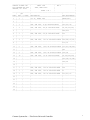
-------------------------------------------------------------------------------CONNECT SYSTEMS INC. |
PARTS LIST
|
REV C
|
1802 EASTMAN AVE #116 |
PCBA, MODEL 9900
|
|
VENTURA, CA. 93003
|
|
|
|
SHEET 1 OF 7
|
|
-------------------------------------------------------------------------------|
QTY
|
|
|
ITEM | UNIT | ISSUED |DESCRIPTION
|REF DESIGNATION |
=====|======|=========|=======================================|================|
1
| 1
|
|P.C.B., MODEL 9900
|MODEL 9900
|
-----|------|---------|---------------------------------------|----------------|
2
|
|
|
|
|
-----|------|---------|---------------------------------------|----------------|
3
| 3
|
|CAP, SMD 0805, 33 pF 08055A330JAT2A
|C60,C61,C43
|
-----|------|---------|---------------------------------------|----------------|
4
| 6
|
|CAP, SMD 0805, 120 pF 08055A121JAT2A
|C9,C25,C30,C50, |
-----|------|---------|---------------------------------------|----------------|
5
|
|
|
|C99,C102
|
-----|------|---------|---------------------------------------|----------------|
6
| 1
|
|CAP, SMD 0805, 270 pF 08055A271JAT2A
|C13
|
-----|------|---------|---------------------------------------|----------------|
7
|
|
|
|
|
-----|------|---------|---------------------------------------|----------------|
8
| 6
|
|CAP, SMD 0805, .001 uF 008055C102JAT2A |C54,C69,C70,C71,|
-----|------|---------|---------------------------------------|----------------|
9
|
|
|
|C72,C73
|
-----|------|---------|---------------------------------------|----------------|
10 | 5
|
|CAP, SMD 0805, .0022 uF 08055C222JAT2A |C10,C87,C88,C89,|
-----|------|---------|---------------------------------------|----------------|
11 |
|
|
|C90
|
-----|------|---------|---------------------------------------|----------------|
12 | 2
|
|CAP, SMD 0805, .0047 uF 08055C472JAT2A |C28,C38
|
-----|------|---------|---------------------------------------|----------------|
13 | 10 |
|CAP, SMD 0805, .01 uF 08055C103JAT2A
|C6,C24,C40,C44, |
-----|------|---------|---------------------------------------|----------------|
14 |
|
|
|C45,C46,C47,C48,|
-----|------|---------|---------------------------------------|----------------|
15 |
|
|
|C49,C91
|
-----|------|---------|---------------------------------------|----------------|
16 |
|
|
|
|
-----|------|---------|---------------------------------------|----------------|
17 | 1
|
|CAP, SMD 0805, .015 uF 08055C153JAT2A |C39
|
-----|------|---------|---------------------------------------|----------------|
18 | 1
|
|CAP, SMD 0805, .022 uF 08055C223JAT2A |C7
|
-----|------|---------|---------------------------------------|----------------|
19 | 3
|
|CAP, SMD 0805, .047 uF 08055C473JAT2A |C11,C27,C37
|
-----|------|---------|---------------------------------------|----------------|
20 |
|
|
|
|
-----|------|---------|---------------------------------------|----------------|
21 |
|
|
|
|
-----|------|---------|---------------------------------------|----------------|
22 |
|
|
|
|
-----|------|---------|---------------------------------------|----------------|
23 |
|
|
|
|
-----|------|---------|---------------------------------------|----------------|
24 |
|
|
|
|
-----|------|---------|---------------------------------------|----------------|
Connect Systems Inc. - Flex Series Universal Controller
1
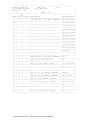
-------------------------------------------------------------------------------CONNECT SYSTEMS INC. |
PARTS LIST
|
REV C
|
1802 EASTMAN AVE #116 |
PCBA, MODEL 9900
|
|
VENTURA, CA. 93003
|
|
|
|
SHEET 2 OF 7
|
|
-------------------------------------------------------------------------------|
QTY
|
|
|
ITEM | UNIT | ISSUED |DESCRIPTION
|REF DESIGNATION |
=====|======|=========|=======================================|================|
25 | 42 |
|CAP, SMD 0805, .1 uF 08055C104KAT2A
|C1,C4,C12,C16, |
-----|------|---------|---------------------------------------|----------------|
26 |
|
|
|C17,C19,C20,C21,|
-----|------|---------|---------------------------------------|----------------|
27 |
|
|
|C22,C23,C32,C33,|
-----|------|---------|---------------------------------------|----------------|
28 |
|
|
|C34,C36,C41,C42,|
-----|------|---------|---------------------------------------|----------------|
29 |
|
|
|C55,C56,C57,C59,|
-----|------|---------|---------------------------------------|----------------|
30 |
|
|
|C62,C63,C64,C65,|
-----|------|---------|---------------------------------------|----------------|
31 |
|
|
|C66,C67,C68,C74,|
-----|------|---------|---------------------------------------|----------------|
32 |
|
|
|C75,C76,C77,C78,|
-----|------|---------|---------------------------------------|----------------|
33 |
|
|
|C79,C81,C84,C86,|
-----|------|---------|---------------------------------------|----------------|
34 |
|
|
|C93,C96,C97,C98,|
-----|------|---------|---------------------------------------|----------------|
35 |
|
|
|C100,C101
|
-----|------|---------|---------------------------------------|----------------|
36 |
|
|
|
|
-----|------|---------|---------------------------------------|----------------|
37 | 1
|
|CAP, SMD 0805, .22 uF 08053C224KAT2A
|C29
|
-----|------|---------|---------------------------------------|----------------|
38 | 1
|
|CAP, .47 uF, 250V, EF2474-NO
|C3
|
-----|------|---------|---------------------------------------|----------------|
39 | 5
|
|CAP, 1 uF, 50V, ELECT, 50TWSS1
|C5,C14,C18,C31, |
-----|------|---------|---------------------------------------|----------------|
40 |
|
|
|C92
|
-----|------|---------|---------------------------------------|----------------|
41 |
|
|
|
|
-----|------|---------|---------------------------------------|----------------|
42 | 2
|
|CAP, 2.2 uF, 50V, ELECT, 50TWSS2R2
|C94,C95
|
-----|------|---------|---------------------------------------|----------------|
43 | 3
|
|CAP, 4.7 uF, 50V, ELECT, 50TWSS4R7
|C26,C51,C58
|
-----|------|---------|---------------------------------------|----------------|
44 | 1
|
|CAP, 10 uF, 50V, ELECT, 50TWSS10
|C8
|
-----|------|---------|---------------------------------------|----------------|
45 | 5
|
|CAP, 33 uF, 25V, ELECT, 25TWSS33
|C2,C15,C82,C83, |
-----|------|---------|---------------------------------------|----------------|
46 |
|
|
|C85
|
-----|------|---------|---------------------------------------|----------------|
47 |
|
|
|
|
-----|------|---------|---------------------------------------|----------------|
48 | 1
|
|CAP, 47 uF, 35V, ELECT, 35TWSS47
|C35
|
-----|------|---------|---------------------------------------|----------------|
Connect Systems Inc. - Flex Series Universal Controller
2
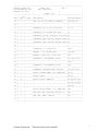
-------------------------------------------------------------------------------CONNECT SYSTEMS INC. |
PARTS LIST
|
REV C
|
1802 EASTMAN AVE #116 |
PCBA, MODEL 9900
|
|
VENTURA, CA. 93003
|
|
|
|
SHEET 3 OF 7
|
|
-------------------------------------------------------------------------------|
QTY
|
|
|
ITEM | UNIT | ISSUED |DESCRIPTION
|REF DESIGNATION |
=====|======|=========|=======================================|================|
49 | 3
|
|CAP, 220 uF, 35V, ELECT, 35TWSS220
|C52,C53,C80
|
-----|------|---------|---------------------------------------|----------------|
50 |
|
|
|
|
-----|------|---------|---------------------------------------|----------------|
51 | 2
|
|CONNECTOR, RJ11, 6 POS, 66011-002
|J1-J2
|
-----|------|---------|---------------------------------------|----------------|
52 | 1
|
|CONNECTOR, 10 POS BARR BLK 70810C
|J3
|
-----|------|---------|---------------------------------------|----------------|
53 | 1
|
|CONNECTOR, 8P HDR, LONG PIN, 22-03-2082|J4
|
-----|------|---------|---------------------------------------|----------------|
54 | 1
|
|CONNECTOR, DB9P, RT ANG, DE9P318,104942|J6
|
-----|------|---------|---------------------------------------|----------------|
55 | 1
|
|CONNECTOR, DP9S, RT ANG, DE9S318,104951|J5
|
-----|------|---------|---------------------------------------|----------------|
56 |
|
|
|
|
-----|------|---------|---------------------------------------|----------------|
57 | 1
|
|CONNECTOR, 2 x 5,FAN-10SGS
|JTAG
|
-----|------|---------|---------------------------------------|----------------|
58 | 2
|
|HEADER, 2 x 4 PIN TDB-08SGS
|JP3-JP10
|
-----|------|---------|---------------------------------------|----------------|
59 | 1
|
|HEADER, 14 PIN, 2X7, 10-88-1141
|LCD
|
-----|------|---------|---------------------------------------|----------------|
60 | 4
|
|CONNECTOR, 2 PIN HEADER, TD-2SG
|JP1,JP11,JP15, |
-----|------|---------|---------------------------------------|----------------|
61 |
|
|
|JP16
|
-----|------|---------|---------------------------------------|----------------|
62 | 1
|
|CONNECTOR, 3 PIN HEADER, TD-3SG
|JP2
|
-----|------|---------|---------------------------------------|----------------|
63 | 3
|
|CONNECTOR, SHORTING BLOCK, DM-2GM-0
|JP1,JP15,JP16
|
-----|------|---------|---------------------------------------|----------------|
64 | 2
|
|DIODE, 1N5245B,ZENER, 15V, CMBZ5245B
|D1-D2
|
-----|------|---------|---------------------------------------|----------------|
65 | 2
|
|DIODE, 1N4004
|D3,D17
|
-----|------|---------|---------------------------------------|----------------|
66 | 11 |
|DIODE, 1N4148, MMBD4148
|D4,D5,D6,D7,D8, |
-----|------|---------|---------------------------------------|----------------|
67 |
|
|
|D9,D10,D11,D16, |
-----|------|---------|---------------------------------------|----------------|
68 |
|
|
|D18,D19
|
-----|------|---------|---------------------------------------|----------------|
69 | 1
|
|DIODE, 1N5231B,ZENER, 5.1V, CMBZ5231B |D14
|
-----|------|---------|---------------------------------------|----------------|
70 | 1
|
|LED ASSY, RED, LL64233R, LTL-523-11
|D15
|
-----|------|---------|---------------------------------------|----------------|
71 | 1
|
|LED, RED, SMALL, 35BL504
|D12
|
-----|------|---------|---------------------------------------|----------------|
72 |
|
|
|
|
-----|------|---------|---------------------------------------|----------------|
Connect Systems Inc. - Flex Series Universal Controller
3
-------------------------------------------------------------------------------CONNECT SYSTEMS INC. |
PARTS LIST
|
REV C
|
1802 EASTMAN AVE #116 |
PCBA, MODEL 9900
|
|
VENTURA, CA. 93003
|
|
|
|
SHEET 4 OF 7
|
|
-------------------------------------------------------------------------------|
QTY
|
|
|
ITEM | UNIT | ISSUED |DESCRIPTION
|REF DESIGNATION |
=====|======|=========|=======================================|================|
73 | 2
|
|FUSE, 255.250
|F1,F2
|
-----|------|---------|---------------------------------------|----------------|
74 | 1
|
|FUSE, 2 AMP, 473.002
|F3
|
-----|------|---------|---------------------------------------|----------------|
75 | 2
|
|I.C. H11AA4.S, OPTOISOLATOR
|Q1,Q2
|
-----|------|---------|---------------------------------------|----------------|
76 | 2
|
|I.C. 4N25.S-M, OPTOISOLATOR
|Q3,Q4
|
-----|------|---------|---------------------------------------|----------------|
77 | 7
|
|I.C. LF347M, QUAD OP AMP
|U1,U4,U5,U6,U10,|
-----|------|---------|---------------------------------------|----------------|
78 |
|
|
|U13,U18
|
-----|------|---------|---------------------------------------|----------------|
79 |
|
|
|
|
-----|------|---------|---------------------------------------|----------------|
80 | 2
|
|I.C. M-88L70-01S, DTMF DECODER
|U3,U7
|
-----|------|---------|---------------------------------------|----------------|
81 | 1
|
|I.C. uA78M33CKC, 3.3 V REGULATOR
|U8
|
-----|------|---------|---------------------------------------|----------------|
82 | 1
|
|I.C. LM78L05ACM, 5.0 V REGULATOR
|U9
|
-----|------|---------|---------------------------------------|----------------|
83 |
|
|
|
|
-----|------|---------|---------------------------------------|----------------|
84 |
|
|
|
|
-----|------|---------|---------------------------------------|----------------|
85 | 1
|
|I.C. MAX3221CAE, RS232 INTERFACE
|U12
|
-----|------|---------|---------------------------------------|----------------|
86 | 1
|
|I.C. 24LC256I/SN, 256K IIC EEPROM
|U14
|
-----|------|---------|---------------------------------------|----------------|
87 | 1
|
|I.C. C8051F124, MICROPROCESSOR
|U15
|
-----|------|---------|---------------------------------------|----------------|
88 | 1
|
|I.C. SP3485CN, RS485 TRANCEIVER
|U16
|
-----|------|---------|---------------------------------------|----------------|
89 |
|
|
|
|
-----|------|---------|---------------------------------------|----------------|
90 | 1
|
|I.C. ISD4002-120S, VOICE RECORDER
|U17
|
-----|------|---------|---------------------------------------|----------------|
91 | 2
|
|I.C. MAX7413CUA, 5th ORDER BESSEL FLTR |U19,U20
|
-----|------|---------|---------------------------------------|----------------|
92 |
|
|
|
|
-----|------|---------|---------------------------------------|----------------|
93 | 1
|
|POT, 2K, 3386P-1-202
|P1
|
-----|------|---------|---------------------------------------|----------------|
94 | 5
|
|POT, 10K, 3386P-1-103
|P3,P4,P5,P6,P7 |
-----|------|---------|---------------------------------------|----------------|
95 | 1
|
|POT, 100K, 3386P-1-104
|P8
|
-----|------|---------|---------------------------------------|----------------|
96 |
|
|
|
|
-----|------|---------|---------------------------------------|----------------|
Connect Systems Inc. - Flex Series Universal Controller
4
-------------------------------------------------------------------------------CONNECT SYSTEMS INC. |
PARTS LIST
|
REV A
|
1802 EASTMAN AVE #116 |
PCBA, MODEL 9900
|
|
VENTURA, CA. 93003
|
|
|
|
SHEET 5 OF 7
|
|
-------------------------------------------------------------------------------|
QTY
|
|
|
ITEM | UNIT | ISSUED |DESCRIPTION
|REF DESIGNATION |
=====|======|=========|=======================================|================|
97 | 2
|
|RELAY, G5V-2-DC12
|RLY1,RLY2
|
-----|------|---------|---------------------------------------|----------------|
98 |
|
|
|
|
-----|------|---------|---------------------------------------|----------------|
99 | 1
|
|RESISTOR, 1/2 W, 100, CARBON FILM
|R13
|
-----|------|---------|---------------------------------------|----------------|
100 | 3
|
|RESISTOR, 1/2 W, 220, CARBON FILM
|R9,R12,R14
|
-----|------|---------|---------------------------------------|----------------|
101 | 1
|
|RESISTOR, 1/2 W, 1K, CARBON FILM
|R4
|
-----|------|---------|---------------------------------------|----------------|
102 | 1
|
|RESISTOR, 1/2 W, 22K, CARBON FILM
|R3
|
-----|------|---------|---------------------------------------|----------------|
103 | 1
|
|RESISTOR, 1/2 W, 33K, CARBON FILM
|R6
|
-----|------|---------|---------------------------------------|----------------|
104 | 2
|
|RESISTOR, 1/4 W, 620, CARBON FILM
|R16,R20
|
-----|------|---------|---------------------------------------|----------------|
105 | 1
|
|RESISTOR, SMD 0805, 0
|R1
|
-----|------|---------|---------------------------------------|----------------|
106 | 1
|
|RESISTOR, SMD 0805, 100
|R21
|
-----|------|---------|---------------------------------------|----------------|
107 | 1
|
|RESISTOR, SMD 0805, 240
|R19
|
-----|------|---------|---------------------------------------|----------------|
108 | 1
|
|RESISTOR, SMD 0805, 470
|R52
|
-----|------|---------|---------------------------------------|----------------|
109 | 1
|
|RESISTOR, SMD 0805, 620
|R83
|
-----|------|---------|---------------------------------------|----------------|
110 |
|
|
|
|
-----|------|---------|---------------------------------------|----------------|
111 | 8
|
|RESISTOR, SMD 0805, 1K
|R26,R39,R59,R73,|
-----|------|---------|---------------------------------------|----------------|
112 |
|
|
|R82,R84,R90,R96,|
-----|------|---------|---------------------------------------|----------------|
113 | 2
|
|RESISTOR, SMD 0805, 1.1K
|R32,R64
|
-----|------|---------|---------------------------------------|----------------|
114 | 1
|
|RESISTOR, SMD 0805, 2K
|R114
|
-----|------|---------|---------------------------------------|----------------|
115 | 10
|
|RESISTOR, SMD 0805, 2.2K
|R17,R27,R44,R62 |
-----|------|---------|---------------------------------------|----------------|
116 |
|
|
|R85,R86,R87,R97,|
-----|------|---------|---------------------------------------|----------------|
117 |
|
|
|R107,R110
|
-----|------|---------|---------------------------------------|----------------|
118 | 1
|
|RESISTOR, SMD 0805, 3.3K
|R104
|
-----|------|---------|---------------------------------------|----------------|
119 | 2
|
|RESISTOR, SMD 0805, 4.7K
|R43,R103
|
-----|------|---------|---------------------------------------|----------------|
120 |
|
|
|
|
-----|------|---------|---------------------------------------|----------------|
Connect Systems Inc. - Flex Series Universal Controller
5
-------------------------------------------------------------------------------CONNECT SYSTEMS INC. |
PARTS LIST
|
REV A
|
1802 EASTMAN AVE #116 |
PCBA, MODEL 9900
|
|
VENTURA, CA. 93003
|
|
|
|
SHEET 6 OF 7
|
|
-------------------------------------------------------------------------------|
QTY
|
|
|
ITEM | UNIT | ISSUED |DESCRIPTION
|REF DESIGNATION |
=====|======|=========|=======================================|================|
121 | 12 |
|RESISTOR, SMD 0805, 5.1K
|R25,R58,R72,R78,|
-----|------|---------|---------------------------------------|----------------|
122 |
|
|
|R81,R91,R94,R98,|
-----|------|---------|---------------------------------------|----------------|
123 |
|
|
|R108,R109,R113, |
-----|------|---------|---------------------------------------|----------------|
124 |
|
|
|R115
|
-----|------|---------|---------------------------------------|----------------|
125 | 2
|
|RESISTOR, SMD 0805, 8.2K
|R63,R106
|
-----|------|---------|---------------------------------------|----------------|
126 | 2
|
|RESISTOR, SMD 0805, 10K
|R38,R41
|
-----|------|---------|---------------------------------------|----------------|
127 | 1
|
|RESISTOR, SMD 0805, 12K
|R70
|
-----|------|---------|---------------------------------------|----------------|
128 | 1
|
|RESISTOR, SMD 0805, 13K
|R105
|
-----|------|---------|---------------------------------------|----------------|
129 | 2
|
|RESISTOR, SMD 0805, 15K
|R30,R47
|
-----|------|---------|---------------------------------------|----------------|
130 | 2
|
|RESISTOR, SMD 0805, 18K
|R29,R46
|
-----|------|---------|---------------------------------------|----------------|
131 | 4
|
|RESISTOR, SMD 0805, 22K
|R10,R22,R31,R95 |
-----|------|---------|---------------------------------------|----------------|
132 | 2
|
|RESISTOR, SMD 0805, 27K
|R18,R116
|
-----|------|---------|---------------------------------------|----------------|
133 | 15 |
|RESISTOR, SMD 0805, 33K
|R2,R8,R65,R68, |
-----|------|---------|---------------------------------------|----------------|
134 |
|
|
|R79,R80,R88,R89,|
-----|------|---------|---------------------------------------|----------------|
135 |
|
|
|R92,R93,R99,
|
-----|------|---------|---------------------------------------|----------------|
136 |
|
|
|R100,R101,R102, |
-----|------|---------|---------------------------------------|----------------|
137 |
|
|
|R112
|
-----|------|---------|---------------------------------------|----------------|
138 | 3
|
|RESISTOR, SMD 0805, 47K
|R66,R67,R76
|
-----|------|---------|---------------------------------------|----------------|
139 | 2
|
|RESISTOR, SMD 0805, 51K
|R53,R54
|
-----|------|---------|---------------------------------------|----------------|
140 | 3
|
|RESISTOR, SMD 0805, 62K
|R55,R56,R69
|
-----|------|---------|---------------------------------------|----------------|
141 | 1
|
|RESISTOR, SMD 0805, 75K
|R51
|
-----|------|---------|---------------------------------------|----------------|
142 | 11 |
|RESISTOR, SMD 0805, 100K
|R24,R34,R35,R37,|
-----|------|---------|---------------------------------------|----------------|
143 |
|
|
|R40,R42,R48,R50,|
-----|------|---------|---------------------------------------|----------------|
144 |
|
|
|R57,R61,R111
|
-----|------|---------|---------------------------------------|----------------|
Connect Systems Inc. - Flex Series Universal Controller
6
-------------------------------------------------------------------------------CONNECT SYSTEMS INC. |
PARTS LIST
|
REV A
|
1802 EASTMAN AVE #116 |
PCBA, MODEL 9900
|
|
VENTURA, CA. 93003
|
|
|
|
SHEET 7 OF 7
|
|
-------------------------------------------------------------------------------|
QTY
|
|
|
ITEM | UNIT | ISSUED |DESCRIPTION
|REF DESIGNATION |
=====|======|=========|=======================================|================|
145 | 1
|
|RESISTOR, SMD 0805, 150K
|R36
|
-----|------|---------|---------------------------------------|----------------|
146 | 1
|
|RESISTOR, SMD 0805, 180K
|R71
|
-----|------|---------|---------------------------------------|----------------|
147 | 2
|
|RESISTOR, SMD 0805, 220K
|R60,R77
|
-----|------|---------|---------------------------------------|----------------|
148 | 4
|
|RESISTOR, SMD 0805, 300K
|R23,R33,R49,R74 |
-----|------|---------|---------------------------------------|----------------|
149 | 2
|
|RESISTOR, SMD 0805, 470K
|R28,R75
|
-----|------|---------|---------------------------------------|----------------|
150 | 4
|
|RESISTOR, SMD 0805, 1M
|R5,R7,R11,R15
|
-----|------|---------|---------------------------------------|----------------|
151 | 1
|
|RESISTOR, SMD 0805, 1.5M
|R45
|
-----|------|---------|---------------------------------------|----------------|
152 |
|
|
|
|
-----|------|---------|---------------------------------------|----------------|
153 | 1
|
|SWITCH, 4 POSITION DIP, CTS-206-4
|S1
|
-----|------|---------|---------------------------------------|----------------|
154 | 2
|
|TRANSFORMER, 671-1898
|T1,T2
|
-----|------|---------|---------------------------------------|----------------|
155 |
|
|
|
|
-----|------|---------|---------------------------------------|----------------|
156 | 3
|
|TRANSISTOR, MMBT2907A/MMBT2907A-LT1
|Q5,Q7,Q12
|
-----|------|---------|---------------------------------------|----------------|
157 | 3
|
|TRANSISTOR, MMBTA13/MMBTA13-LT1
|Q6,Q10,Q15
|
-----|------|---------|---------------------------------------|----------------|
158 | 3
|
|TRANSISTOR, MMBT2222A/PMBT2222A
|Q8,Q9,Q11
|
-----|------|---------|---------------------------------------|----------------|
159 |
|
|
|
|
-----|------|---------|---------------------------------------|----------------|
160 | 2
|
|VARISTOR, V250LA20, MOV, 250V
|V1,V2
|
-----|------|---------|---------------------------------------|----------------|
161 |
|
|
|
|
-----|------|---------|---------------------------------------|----------------|
162 | 1
|
|XTAL, 3.58 MHz, KD0048FCB
|Y1
|
-----|------|---------|---------------------------------------|----------------|
163 | 1
|
|XTAL, 22.1184 MHz, FOX 221
|Y2
|
-----|------|---------|---------------------------------------|----------------|
164 |
|
|
|
|
-----|------|---------|---------------------------------------|----------------|
165 | 1
|
|LABOR, ASSEMBLY, 9900 PCB
|
|
-----|------|---------|---------------------------------------|----------------|
166 |
|
|
|
|
-----|------|---------|---------------------------------------|----------------|
167 |
|
|
|
|
-----|------|---------|---------------------------------------|----------------|
168 |
|
|
|
|
-----|------|---------|---------------------------------------|----------------|
Connect Systems Inc. - Flex Series Universal Controller
7
Changes
Version 1.00
Original Manual
Version 1.01 of Manual and 1.3 of Software
Added feature where the restore function for both the
sense and the COS can be disabled. Changes affect
Parameter 13 and Parameter 14.
Connect Systems Inc. - Flex Series Universal Controller
8