1
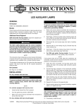
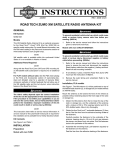
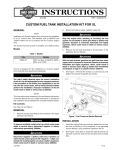
-J03784
REV. 2011-01-13
AUTOMATIC PRIMARY CHAIN TENSIONER
GENERAL
is00561
Kit Number
40063-05B
Models
1
For model fitment information, see the P&A Retail Catalog or
the Parts and Accessories section of www.harley-davidson.com
(English only).
2
3
Additional Parts Required
Proper installation of this kit requires the separate purchase
of a primary cover gasket and other seals, that vary depending
on the model. See your authorized Harley-Davidson dealer for
the proper parts.
4
Loctite® 262 Threadlocker and Sealant (red) (94759-99) is
required for proper installation on 1985-2000 model motorcycles.
The rider's safety depends upon the correct installation
of this kit. Use the appropriate service manual procedures.
If the procedure is not within your capabilities or you do
not have the correct tools, have a Harley-Davidson dealer
perform the installation. Improper installation of this kit
could result in death or serious injury. (00333a)
1.
2.
3.
4.
5.
Screw (2)
Anchor plate
Nut and washer
Manual tensioner
Screw (2)
Figure 1. Manual Tensioner: 1985-2000 Models
4.
For 1985-2000 model motorcycles, remove manual
tensioner and replace the carriage bolt as follows:
a.
See Figure 1. Remove two screws (5) and nut and
washer (3), and remove chain tensioner (4).
b.
Remove two screws (1) and anchor plate (2).
c.
Replace the carriage bolt in the anchor plate with the
carriage bolt from the kit.
d.
Apply 2-3 drops of Loctite 262 (red) to the threads of
the anchor plate mounting screws (1), then install
anchor plate and two screws. Tighten screws to 1214 ft-lbs (16-19 Nm).
NOTE
This instruction sheet references Service Manual information.
A Service Manual for your model motorcycle is required for
this installation and is available from a Harley-Davidson Dealer.
Kit Contents
See Figure 7 and Table 1.
INSTALLATION
1.
Refer to the appropriate Service Manual and remove seat.
5
For 2001 and later model motorcycles, remove manual
tensioner as follows:
a.
See Figure 2. Remove nut and washer (1) and
remove chain tensioner (2).
To prevent accidental vehicle start-up, which could cause
death or serious injury, disconnect negative (-) battery
cable before proceeding. (00048a)
2.
Disconnect negative (-) battery cable.
3.
Refer to the appropriate Service Manual and remove
primary cover.
-J03784
Many Harley-Davidson® Parts & Accessories are made of plastics and metals which can be recycled.
Please dispose of materials responsibly.
1 of 3
11. Refer to the appropriate Service Manual and install the
seat.
is00562
is00563
1
1
2
2
1. Nut and washer
2. Tensioner
Figure 2. Manual Tensioner: 2001 and Later
5.
See Figure 3. Install the autotensioner bracket (2) over
the carriage bolt (1), behind the primary chain. Loosely
secure the bracket using the nut and washer removed in
Step 4.
6.
See Figure 4. Install autotensioner (2) to the autotensioner
bracket with two screws (3) from the kit. Do not tighten
screws at this time.
7.
See Figure 4. Position the autotensioner and bracket as
follows:
8.
9.
1. Carriage bolt
2. Autotensioner bracket
a.
Carefully lift the autotensioner and bracket assembly
to take the slack out of the chain.
b.
Lower the autotensioner and bracket assembly 1-2
notches to allow approximately 1 in. (25 mm) of chain
freeplay at the top of the chain.
c.
Tighten nut (1) to 21-29 ft-lbs (29-39 Nm).
d.
Tighten autotensioner hex screws (3) to 17-19 ft-lbs
(23-26 Nm).
Figure 3. Autotensioner Bracket
is00563
1
2
3
1.
2.
3.
4.
Remove tie wrap and shipping plate (4) to free the
autotensioner. Flex the top of the chain to allow the
autotensioner to adjust itself.
4
Nut and washer
Autotensioner
Hex screw (2)
Shipping plate
Figure 4. Autotensioner
Once the shipping plate is removed and the chain is flexed,
the spring-loaded wedge of the autotensioner should move
to the left. If the shoe does not move up and down when
the chain is flexed, then the autotensioner bracket is
positioned too high and must be lowered. Install the shipping plate or a tie wrap to secure the shoe, loosen the nut
and screws, lower the assembly, and re-tighten the nut
and screws according to the specifications above. Then
repeat this step.
CARE & MAINTENANCE
Refer to the appropriate Service Manual and install the
primary cover with a new seals and refill the primary oil.
Resetting the Autotensioner
Removing the Autotensioner for Service
1.
Use a tie wrap and secure the shoe to the base of the
autotensioner, without securing it to the autotensioner
bracket. This will retain the autotensioner adjustment for
reinstallation during service.
2.
Remove two autotensioner hex screws, and autotensioner.
1.
See Figure 5. Compress autotensioner wedge (1) and
spring back to the base.
2.
Hold wedge in position by inserting a hex wrench or pick
tool through the hole in the base of the autotensioner.
3.
See Figure 6. Move plastic autotensioner shoe (1) into
place as shown.
4.
If available, install shipping plate (2) to secure the shoe
to the base. If it is not available, secure the shoe to the
base with a tie wrap.
10. Connect the negative (-) battery cable.
After installing seat, pull upward on seat to be sure it is
locked in position. While riding, a loose seat can shift
causing loss of control, which could result in death or
serious injury. (00070b)
-J03784
2 of 3
SERVICE PARTS
is00572
is00558
1
1
3
1. Autotensioner wedge
Figure 5. Reset Autotensioner Spring and Wedge
4
2
is00573
2
1
Figure 7. Service Parts for Automatic Primary Chain
Tensioner Kit
Table 1. Service Parts
Item
2
1. Autotensioner shoe
2. Shipping plate
Figure 6. Install Shipping Plate or Tie Strap
-J03784
Description (Quantity)
Part Number
1
Carriage bolt, 3/8-16 X 1-1/4 in. 5416
(use for 1985-2000 models only)
2
Screw, hex, 5/16-18 X 1-1/2 in. 2932A
(2)
3
Bracket, autotensioner
40065-05
4
Autotensioner
Not Sold
3 of 3