1
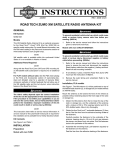
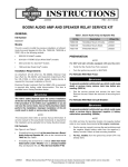
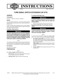
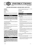
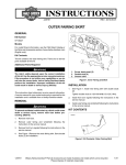
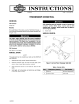
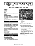
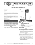
-J06017
REV. 2014-04-03
TURN SIGNAL SWITCH EXTENSION CAP KITS
Kit Numbers
NOTE
It is not necessary to disconnect the switch wiring to replace
the turn signal switch caps.
71500285, 71500286
2.
See Figure 1. Carefully pry the edge (3) of the currently
installed turn signal switch cap (2) up off the switch
module.
3.
Repeat for the opposite-side switch housing and cap.
GENERAL
Models
For model fitment information, see the P&A retail catalog or
the Parts and Accessories section of www.harley-davidson.com
(English only).
is08334
These turn signal switch extension caps are a direct replacement for the original equipment (OE) turn signal switch caps.
These kits install in the same manner as original equipment
(OE).
1
2
Installation Requirements
3
The rider's safety depends upon the correct installation
of this kit. Use the appropriate service manual procedures.
If the procedure is not within your capabilities or you do
not have the correct tools, have a Harley-Davidson dealer
perform the installation. Improper installation of this kit
could result in death or serious injury. (00333a)
1. Switch housing
2. Switch cap
3. Edge of switch cap
Figure 1. Switch Cap Removal (Left Side Shown)
NOTE
This instruction sheet refers to service manual information. A
service manual for this year/model motorcycle is required for
this installation. One is available from a Harley-Davidson dealer.
Kit Contents
INSTALLATION
1.
Install the left side and right side handlebar switch housing
assemblies per the service manual.
2.
See Figure 3. Select the correct turn signal switch extension cap from the kit.
3.
See Figure 2. Install the extension cap (2) on the inboard
side first. Then press the outboard side down until an
audible click is heard.
See Figure 3 and Table 1.
PREPARATION
To prevent accidental vehicle start-up, which could cause
death or serious injury, remove main fuse before proceeding. (00251b)
1.
is08335
1
See the service manual to remove the main fuse.
To prevent accidental vehicle start-up, which could cause
death or serious injury, disconnect negative (-) battery
cable before proceeding. (00048a)
1.
Turn the ignition key switch OFF unless already done.
REMOVAL
1.
Remove the left side and right side handlebar switch
housing assemblies per the service manual.
-J06017
2
1. Switch housing
2. Switch extension cap
Figure 2. Switch Extension Cap Installation (Left Side
Shown)
Many Harley-Davidson® Parts & Accessories are made of plastics and metals which can be recycled.
Please dispose of materials responsibly.
1 of 2
4.
Toggle the switch back and forth, checking for proper
operation.
5.
Repeat steps for the opposite-side turn signal switch.
6.
Remove and dispose of the old switch caps.
1.
See the service manual install the main fuse.
After installing seat, pull upward on seat to be sure it is
locked in position. While riding, a loose seat can shift
causing loss of control, which could result in death or
serious injury. (00070b)
COMPLETION
NOTE
To prevent possible damage to the sound system, verify that
the ignition switch is OFF before installing the main fuse or
attaching the battery cables.
2.
See the service manual to install the seat.
3.
Test all the handlebar switches for proper operation.
SERVICE PARTS
is08336a
4
1
5
2
6
3
Figure 3. Turn Signal Switch Extension Cap Kits
SERVICE PARTS
Table 1. Service Parts
Kit
Item
Kit 71500285
(Models without Information and Communication
systems)
1
Turn Signal Switch Extension Cap Kit (includes Items 2-3)
71500285
2
•
Switch extension cap, right turn
Not sold separately
3
•
Switch extension cap, left turn
Not sold separately
Kit 71500286
(Models with Information
and Communication systems)
4
Turn Signal Switch Extension Cap Kit (includes Items 5-6)
71500286
5
•
Switch extension cap, right turn (information icon)
Not sold separately
6
•
Switch extension cap, left turn (communication icon)
Not sold separately
-J06017
Description (Quantity)
Part Number
2 of 2