1
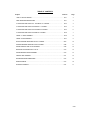
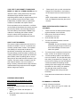
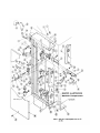
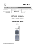
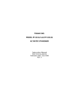
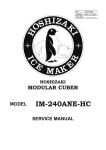
Revision 3-1975
MODEL A &
MODEL A I
STEAM COOKERS
Manual & Automatic
PARTS and SERVICE
MANUAL
Market Forge
Everett Ma. 01249 Tel. 387-4100
Facsimile #617-387-4456
5099
TABLE OF CONTENTS
Subject
Code No.
Page
HOW TO USE THIS MANUAL ................................……………………………………………. 5101
3
BASIC OPERATING INSTRUCTIONS ......................……………………………………….....
5101
3
ILLUSTRATION AND PARTS LIST - AUTOMATIC A-1 COOKER ...………………………...
5102
4
ILLUSTRATION AND PARTS LIST-MANUAL A-1 COOKER ...……………………………....
5103
5
ILLUSTRATION AND PARTS LIST-AUTOMATIC A COOKER ..……………………………...
5104
6
ILLUSTRATION AND PARTS LIST-MANUAL A COOKER .......………………………………. 5108
7
MODEL A-1 DOOR ASSEMBLY ................. .............. …………………………………………. 5106
8
MODEL A DOOR ASSEMBLY ................................……………………………………………. 5107
9
WATTS PRESSURE REDUCING VALVE-A-1 COOKER .........……………………………….. 5010
10
STRONG PRESSURE REDUCING VALVE-A COOKER ........………………………………… 5108
11
STEAM MANIFOLD AND VALVE ASSEMBLY. .............…………………………………...... . 5109
12
SERVICING THE STEAM SUPPLY VALVE ..................……………………………………..... 5110
13
STEAM PRESSURE GAUGE ASSEMBLY .....................………………………………………. 5110
13
CONTROL BOX ASSEMBLY ...............................……………………………………………... 5111
14
SUGGESTED STEAM CONNECTIONS ...................………………………………………......
5112
15
WIRING DIAGRAM ......................................…………………………………………………….. 5113
16
SCHEMATIC DIAGRAM ..............................…………………………………………………...... 5114
17
5100
YOUR "SET IT AND FORGET IT" MARK-FORE
MODEL "A" AND "A-1" STEAM COOKERS are the
3.
ultimate in steam cooking advancement and were
developed through extensive research and
engineering skills to satisfy an urgent demand for an
easy-to-operate, easy-to-service steam cooker.
NOTE- All part orders received before 2:00
P.M. are shipped the same day the order is
received.
Independently controlled cooking compartments
constitute a remarkable and superior feature.
Each compartment can be used alone, or all three
can be employed simultaneously because each has
its own timing, steam control and signal devices.
The careful factory workmanship of Market Forge
craftsmen in developing this newest scientific
triumph in steam cooking equipment is your
guarantee of efficient, dependable performances.
BASIC OPERATING INSTRUCTIONS FOR
AUTOMATIC
1.
Check to be sure the steam pressure gauge
regis-ters between 4 and 5 pounds.
2.
Place pans of food into the cooking
compartment to be used.
3.
Close and latch the door.
4.
Turn the door wheel clockwise to seal the
cooking compartment.
HOW TO USE THIS MANUAL
This manual contains maintenance and service instructions for Model "A" and "A-1" automatic and
manually operated steam cookers. The exploded
view drawings of components are aids to the
identification, disassembly and assembly of parts.
The parts listings provide information necessary for
ordering replacement parts (proper part names and
part numbers). When requesting parts or service,
always furnish the model and serial number of your
machine. The serial number is located on the left
side under the bezzel on the con-trol panel. A
listing of Factory Authorized Service Agencies who
maintain Market Forge equipment will be supplied
without charge upon request.
Please specify how you wish merchandise
shipped. If this information is not furnished
we will ship the best and most economical
way.
WARNING: Do not permit steam to leak.
Set the door tight enough to make a firm
seal. Steam leakage will cause undue
wear to the gasket.
5.
Turn timer pointer clockwise to the 60 minute
mark, and then to the desired cooking time.
6.
Pull the-operating handle out and allow it to
lock in this position. The pilot light will signify
this cooking compartment is in operation. At
the end of the cooking cycle the AUTOMATIC
controls will release the operating handle,
shutting off the steam supply and exhausting
the steam from the cooking com-partment.
The pilot light will be turned off and the
buzzer will signify that cooking has been
terminated.
7.
Press the buzzer release knob to silence the
buzzer.
ORDERING REPAIR PARTS
Many repair parts on the Model "A1" steam
cooker are not interchangeable with parts on
the "A" cooker. It is necessary, therefore, to
furnish the following information when ordering
repair parts.
FOR MANUALLY OPERATED
1 through 5 Same as Automatic.
6.
Set timer. When bell rings, lift handle and
push in to shut off cooker.
1. Quantity, part number and description of
part.
2. Model and Serial number for which the part
is required.
5101
Manifold Compartment A-1 Cooker Automatic
* Indicates Interchangeable Parts A1 & Old 'A'
Cooker
Master Illustration
Parts List
ITEM
PART NO.
DESCRIPTION
1
10-2445*
1" O.D. x 3/8 St. St. Washer
2
10-2328 *
1/4" x 20" Elastic Stop Nut
3
10-2652 *
Gasket
4
10-3343*
Lock nut
5
10-2988*
Rd. Hd. Rivet
6
10-2427
1/2" I.D. Plated washer
7
10-2777
3/8" O.D. x 1 1/2" long spring
8
90-8331
Latch Handle Ass'y.
9
10-2328
Stop Nut
10
10-2755 *
Spring-Operating Arm
11
10-2331
No. 6-32 Hex Nut (Cad. PI.)
12
90-9212
Operating Handle Ass'y.
13
90-9215
Control Handle
14
10-1881
No. 10-32 x 3/8 Fl. Hd. Screw
15
10-1967
Shoulder Screw for linkage
16
90-8926
Signal light term ass'y.
17
90-9214
Shaft Reset Button
18
90-8537*
Valve Actuating Arm
19
10-2756*
Synchronizer Spring
20
10-2515*
No. 6 Lock Washer
21
90-7189
Timer Knob
22
10-4748*
Pressure Gauge
23
90-8963
Copper Tubing 3/16" O.D. x 18"
10-4370
Brass Nut
10-4371
Brass Sleeve (Female)
90-9219
Bezel (2 comp.)
90-9220
Bezel (3 comp.)
90-7537
Bezel (4 comp.) Pol. Only
25
10-6238
Identification Name plate
26
10-1654
Drive Pin
27
90-8549*
Shield Ass'y. Manifold
28
90-9188
Side Panel-St. St. (2 comp.)
90-9199
Side Panel-St. St. (3 comp.)
90-9203
Side Panel-St. St. (4 comp.)
90-9189
Side Panel—Enamel (2 comp.)
90-9200
Side Panel—Enamel (3 comp.)
29
10-1740
No. 8-32 x 3/4" Truss Head Screw
30
10-2124*
3/8-16 x 1 1/8 Hex Hd. Screw
31
10-2503*
3/8" Lock washer (cad. PI.)
32
10-1059
3/4" Std. 90° street elbow
33
10-3761
Nipple 3/4" IPS 71/4" Ig.
34
10-6156
Steam Trap
35
10-6157
Adapter Sub—ass'y.
36
10-5514*
Timer
37
90-8144
Comb. Steam & Exhaust Header (2 comp.)
90-8145
Comb. Steam & Exhaust Header (3 comp.)
90-8146
Comb. Steam & Exhaust Header (4 comp.)
24
ITEM
PART NO.
DESCRIPTION
38
90-8534*
Pivot Arm
39
10-4742*
Safety Valve 3/4" 8 Ibs. chrome
10-4741*
Safety Valve 3/4" 8 Ibs. brass
40
10-1053
Elbow 3/4" IPS, 90°
41
10-5164*
Junction Box Cover
10-2652
Gasket
42
90-9195
Insulator-Buzzer
43
10-6682
Buzzer
44
10-5997*
Solenoid
45
90-8905
Push Rod-Solenoid
46
10-2160
No. 10-32 x 3/8 Philips Truss Hd. Scr. (Cadm. PI.)
47
10-2505*
No. 10 Lock washer (Cadm. PI.)
48
10-1717
No. 8-32 x 3/8 Rd. Hd. Screw
49
10-2151
No. 6- 32 x 2 1/4 Ig. Rd. Hd. Mach. Screw
50
10-5613*
Micro Switch (Solenoid)
51
10-5511*
Micro Switch (Buzzer)
52
90-9223
Spacer
53
10-2428
Flat Washer
54
90-9226
Name plate Panel—Auto 2 comp.
90-9229
Name plate Panel—Auto 3 comp.
55
56
90-8308
Name plate Panel—Auto 4 comp
10-4619*
Replacement element for Steam Trap painted cap
10-5625*
Replacement element for Steam Trap chrome cap
10-4559*
1/2" Steam trap complete painted (obs)
90-4003*
1/2" Steam Trap complete chrome (obs)
57
10-2154
No. 10 Ty. "B" Pan Hd. Screw 1/2" Ig. (Cad. PI.)
58
10-1975
No. 4-40 x 7/16 Flat Hd.Scr.
59
10-1949
No. 6 Ty. "A" Pan Hd. Screw 3/8 Ig. (Cad. PI.)
60
10-5614*
Junction Box
61
10-5680
Air Adapter
62
10-5972
Fuse Holder Buss H.K.P.
63
10-5973
Fuse Buss M.D.L. 8/10 amp. Slow
64
10-1703
No. 2 Drive Screw
65
90-9237
Top Cover Ass'y. - St. St. (2,3&4 Comp.
90-9238
Top Cover Ass'y. Enamel (2 & 3 Comp.)
90-9186
Bottom Enclosure- St. St.
90-9187
Bottom Enclosure - Enamel
90-9184
Back Side Enclosure - St. St. (2 Comp.)
90-9231
Back Side Enclosure - St. St. (3 comp.)
90-9896
Back Side End. Ass'y. - St. St. (4 comp.)
90-9185
Back Side End. - Enamel (2 comp.)
90-9232
Back Side Enclosure - Enamel (3 comp.)
66
67
5102
* INDICATES INTERCHANGEABLE
PART A1 & A COOKER - MANUAL CONTROLS
Manifold Compartment A-1 Cooker
Master Illustration
Parts List
Manually Operated
ITEM
DESCRIPTION
PART NO.
ITEM
PART NO.
1
102445*
1" O.D. x 3/8 St. St. washer
33
2
102328*
1/4" x 20 Elastic stop nut
3
10-2652*
Gasket
4
103343*
Lock nut
5
10-2988*
Rd. Hd. Rivet
36
6
10-2427
1/2" I.D. plated washer
37
7
10-2777
8
90-8331
3/8" O.D. x 1 1/2" long
spring
Latch Handle Ass'y.
9
10-2328
Stop nut
10
10-2755*
Spring Operating Arm
11
90-9212
Operating Handle Ass'y.
12
10-1967*
Shoulder Screw for linkage
13
90-8534*
Pivot Arm
14
10-1881
No. 10-32 x 3/8 fl. hd. screw
15
90-9215
Control Handle
16
90-8537*
Valve Actuating Arm
17
10-2756*
Synchronizer Spring
18
10-6307
Timer Knob
19
10-5520*
Timer
20
10-4748*
Pressure Gauge
21
90-9219
Bezel (2 comp.)
90-9220
Bezel (3 comp.)
44
10-2154
45
90-9186
Brass Sleeve (Female)
10-3761
Nipple 3/4" IPS 7 1/4" Ig.
34
10-1053
Elbow 3/4" IPS 90°
35
10-4741*
Safety Valve 3/4" 8 Ibs. brass
10-4742*
Safety Valve 3/4" 8 Ibs. chrome
10-1059
3/4" Std. 90°Street Elbow
38
105846
Name plate Panel (2 comp.)
10-5847
Name plate Panel (3 comp.)
90-8312
Name plate Panel (4 comp.)
10-4619*
Replacement element for Steam Trap
Painted cap.
Replacement element for Steam Trap
Chrome cap.
1/2" Steam trap complete
painted (obs)
1/2" Steam trap complete
chrome (obs)
No. 4-40x7/16"
Flat Hd. Scw.
Lock Washer
10-5625*
39
10-4559*
90-4003*
40
10-1975
41
10-2505
42
10-2160
43
909237
909238
90-7537
Bezel (4 comp.) Pol. Only
22
106238
Identification name plate
23
10-1703
No. 2 Drive Screw
24
90-8549*
Shield Ass'y. Manifold
46
10-1949
25
10-2124*
47
90-9184
26
10-2503*
3/8" - 16 x 1 1/8" Hex.
Hd. Cap Screw
3/8" Lock Washer (cad. p .)
27
10-1740
28
90-8144
90-9188
No. 8 - 32 x 3/4 Truss Hd
Screw
Comb. steam & exhaust
header (2 comp.)
Comb. steam & exhaust
header (3 comp.)
Comb. steam & exhaust
header (4 comp.)
Side Panel-St. St. (2 comp.)
90-9199
Side Panel-St. St. (3 comp.)
90-9203
Side Panel-St. St. (4 comp,)
90-9189
Side Panel-Enamel (2 comp.)
90-9200
Side Panel-Enamel (3 comp.)
30
10-6156
Steam Trap
31
10-6157
Adapter Sub—Ass'y.
32
90-8963
Copper Tubing 3/16" O.D. x 18"
10-4370
Brass Nut
90-8145
90-8146
29
DESCRIPTION
10-4371
90-9187
90-9231
90-9896
90-9185
90-9232
No. 10-32 x 3/8 Phil Truss
Hd. Screw
Top Cover Ass'y. - St. St.
(2,3. &4 comp.)
Top Cover Ass'y. - Enamel
(2 &3 comp.)
No. 10 - Ty "B" Pan Hd.
Screw 1/2" Lg. (Cad. PI.)
Bottom Enclosure - St. St.
(2,3, &4 comp.)
Bottom Enclosure — Enamel
(2 & 3 comp.)
No. 6 Ty. "A" Pan Hd. Screw
3/8 Lg. (cad p(.)
Back Side Enclosure - St. St.
(2 comp.)
Back Side Enclosure - St. St.
(3 comp.)
Back Side End. Ass'y. - St. St.
(4 comp.)
Back Side Enclosure - Enamel
(2 comp.)
Back Side Enclosure - Enamel
(3 comp.)
5103
MASTER ILLUSTRATION
Manifold Compartment
Automatically Operated
* INDICATES INTERCHANGEABLE
PARTS
A1 & 'A' COOKER
Manifold Compartment A Cooker
Master Illustration
Item
1
2
3
4
5
6
7
8
9
10
11
12
13
14
15
16
17
18
19
20
21
22
23
24
25
26
27
28
29
30
31
32
33
34
Part No.
10-2445*
10-2328*
10-2652*
10-1910
10-3343*
10-2988*
90-8387
10-2757
90-8546
90-8545
90-8524
90-8550
90-8547
10-1975
10-2505*
10-2339
10-2755*
90-8531
10-1908
90-8669
10-1922
90-8534*
10-1852
90-8537*
90-8533
90-8573
90-8575
90-8577
90-8574
90-8576
90-8578
10-2756*
10-1845
10-5514*
10-5499
10-4713
10-4748*
90-8683
90-8684
10-2339
Automatically Operated
Parts List
Description
1" OD x 3/8 St. St. Washer
1/4-20 Elastic stop nut
7/8 x 1 x 1/16 Composition Gasket
3/16" Tube x 1/8" Taper pipe thread
w/fitting
1/2"
Lock nut Nickel Plated
1/2
x
3 1/2"
Rd.washer
hd. rivet
1/2" I.D.
plated
3/8" O.D. x 1" long Spring
Shaft for reset button
Bracket for reset button
Latch handle assembly
Operating Arm Assembly
Left Bracket
4-40-1/2 Flat hd. screw
10/32 x 1/16" Lock washer
10/32 St. St. hex nut
Spring for Operating Arm
Spring Bracket
1/8" x 1 1/4" drive pin
Operating Handle
8/32 x 1/2 Oval hd. screw cad. pl.
Pivot Arm
10/24 x 3/4 Rd. Hd. mach. screw
cad. actuating arm
pl.
Valve
Shoulder Screw for Linkage
Side Enclosure St. St. 2 comp.
Side Enclosure St. St. 3 comp.
Side Enclosure St. St. 4 comp.
Side Enclosure Painted 2 comp.
Side Enclosure Painted 3 comp.
Side Enclosure Painted 4 comp.
Valve Synchronizer Spring
8/32 x 1/4 St. St. self tapping screw
0-60 minute electric timer
115V Pilot Light
Timer knob
0-30# Pressure Gauge
Bezel 2A
Bezel 3A
#10 Hex nut St. St.
(OBSOLETE)
Item
35
36
37
38
39
40
41
42
43
44
45
46
47
48
49
50
51
52
53
54
55
56
57
58
59
60
Part No.
90-8549*
90-8541
90-8434
90-8435
90-8436
90-8430
90-8431
90-8432
10-4563
10-1888
10-5613*
90-4159
10-2337
10-2503*
10-2124*
Description
Manifold Shield St. St.
Manifold Shield Painted
Side Panel St. St. 2 comp .
Side Panel St. St. 3 comp.
Side Panel St. St. 4 comp.
Side Panel Painted 2 comp.
Side Panel Painted 3 comp.
Side Panel Painted 4 comp.
Buzzer
#10 Cad plated lock washer
Solenoid Micro switch
Insulator
6/32 St. St. hex nut
3/8" Lock washer cad. pl.
3/8" - 16 x 1 1/8" hex hd. cap screw
90-8498
90-8496
90-8604
10-5511*
10-5997*
10-1701
10-2508
90-8542
10-2515*
10-1760
90-4399
90-8739
10-4559*
90-4003*
10-1921
Comb steam & exhaust header
2 comp.
Comb
steam & exhaust header 3
comp.
Comb steam & exhaust header 4 comp.micro switch
Buzzer
115V solenoid
1/4 - 20 x 3/8 Rd hd mach screw cad
pl x 3/32 x 1/16 St. St. lock washer
1/4
Push rod for Solenoid
#6 x 3/6 x 1/32 lock washer cad pl
10/32 x 1/2" St. St. mach screw
Spring clip
Panel clip
1/2" steam trap complete brass
(obs)steam trap complete chrome
1/2"
Retaining screw - side enclosure
104619*
10-5625*
10-5614
10-4742*
10-4741*
10-3455
90-7304
10-5164*
Replacement element for steam trap
-Replacementpainted
elementcap
for steam trap
Junction
boxchrome cap
3/4 - 8# Safety valve chrome
3/4 - 8# Safety valve brass
3/4" B. I. elbow
3/4" chrome elbow
Junction box (Cover)
5104
MASTER ILLUSTRATION
Manifold Compartment
Manually Operated
* INDICATES INTERCHANGEABLE PARTS
A-1'& 'A' COOKER
Manifold Compartment A Cooker
Master Illustration
Manually Operated
(OBSOLETE)
Parts List
Item
Part No.
Description
1
10-2445*
1"O.D.x 3/8" St. St. Washer
Item
Part No.
Description
2
10-2328*
1/4-20 Elastic Stop Nut
25
90-8549*
Manifold Shield St. St.
90-8541
Manifold Shield Painted
90-8434
Side Panel St. St. 2 Comp.
90-8435
Side Panel St. St. 3 Comp.
90-8436
Side Panel St. St. 4 Comp.
90-8430
Side Panel Painted 2 Comp.
90-8431
Side Panel Painted 3 Comp.
3
10-2652*
7/8x1 x 1/16 Composition Gasket
4
10-1910
5
10-3343*
3/16" Tube x 1/8" Taper Pipe Thread w/
Fitting
1/2" Lock nut Nickel Plated
6
10-2988*
1/2" x 3 1/2" Rd.Hd. Rivet
7
90-8387
1/2" I.D. Plated Washer
8
10-2757
3/8" O.D. x 1" Long Spring
9
90-8524
Latch Handle Assembly
10
90-8550
Operating Arm Assembly
11
10-2755*
Spring for Operating Arm
12
90-8669
Operating Handle
13
10-1922
8/32 x 1/2 Oval Hd. Screw Cad. PI.
14
90-8534*
Pivot Arm
15
90-8537*
Valve Actuating Arm
16
17
10-1967*
Shoulder Screw for Linkage
90-8573
Side Enclosure St. St. 2 Comp.
90-8575
Side Enclosure St. St. 3 Comp.
90-8577
Side Enclosure St. St. 4 Comp.
90-8574
Side Enclosure Painted 2 Comp.
90-8576
Side Enclosure Painted 3 Comp.
90-8578
Side Enclosure Painted 4 Comp.
18
10-2756*
Valve Synchronizer Spring
19
10-1845
8/32 x 1/4 St. St. Self Tapping Screw
20
10-5220*
0 - 60 Minute Mechanical Timer
21
10-4713
Timer Knob
22
10-4748*
0 - 30# Pressure Gauge
23
90-8683
Bezel 2A
90-8684
Bezel 3A
10-2339
#10 Hex Nut St. St.
24
26
90-8432
Side Panel Painted 4 Comp.
27
10-2503*
3/8" Lock washer Cad. PI.
28
10-2124*
3/8"-16x1 1/8" Hex. Hd. Cap Screw
29
90-8498
30
90-8739
Comb. Steam Supply & Exhaust Header 2
Comp.
Comb Steam Supply & Exhaust Header 3
Comp.
Comb Steam Supply & Exhaust Header 4
Comp.
Panel Clip
31
10-4559*
1/2" Steam Trap Complete Brass (obs)
90-4003*
1 /2" Steam Trap Complete Chrome
32
10-1921
Retaining Screw - Side Enclosure
33
10-4619*
10-4742*
Replacement Element for Steam Trap
Painted Cap.
Replacement Element for Steam Trap
Chrome Cap.
3/4" - 8# Safety Valve Chrome
10-4741*
3/4" - 8# Safety Valve Brass
10-3455
3/4" B. 1. Elbow
90-7304
3/4 "Chrome Elbow
10-0435
Name Plate 2A
10-0434
Name Plate 3A
90-8583
Name Plate 4 A Upper
90-8588
Name Plate 4A Lower
90-8496
90-8604
10-5625*
34
35
36
5105
MODEL A-1 DOOR ASSEMBLY.
ITEM
PART NO.
DESCRIPTION
1
90-8310
Model A-1 Hand Grip
2
10-1945
3
90-8311
4
10-0433
Model A-1 Door Gasket
5
90-8514
Model A-1 Inner Door
ITEM
PART NO.
Gasket Screws
13
10-1981
Pivot Hinge
Model A-1 Gasket Plate
14
90-8113
Handwheel — Polished Solid
90-8328
Handwheel -Spoked (Enamel)
90-8126
Outer Door Ass'y.— Polished
90-8320
Outer Door Ass'y.— Enameled
16
10-2423
Thrust Washer
17
10-3080
Door Bushing
18
10-1696
Roll Pin
19
90-8124
Strong Back
20
10-2012
Cap Screw
21
10-1973
Support Stud Ass'y.
22
10-2302
Hex. Nut 3/8-16
6
10-2135
5/16-18 x 3/4 Hex. Hd. Bolt
7
10-2426
15
DESCRIPTION
8
10-1909
11/32 I.D. x 3/4 O.D. Flat
Washer St. St.
5/16" Thredseal
9
90-8114
Spring Door Release
10
10-3079
(Pivot Bearing Interchangeable)
11
10-2427
12
90-8111
1/16 Thk. x 1" O.D. Flat
Washer
Hinge — Polished upper and lower
90-8316
Hinge — Enameled upper and lower
23
90-8317
(Bushing for spoke wheel only)
90-8147
Inner Door Ass'y (Items 1-5)
24
10-2013
Hex. Jam Nut 3/8-16
5106
5107
Item
Part No.
Description
1
90-8518
Model A Gasket Plate Handle
2
3
4
5
6
7
10-1704
90-8517
10-0433
90-8514
90-8504
10-2124
8
10-2426
Gasket Screws
Model A Gasket Plate
Model A Door Gasket
Model A Inner Door
Model A Outer Door
3/8" Hex Head Cap Screw x
1-1/8" long St. St.
11/32 I.D. x 3/4' O.D. Flat Washer
St. St.
9
90-8519
10-0427
10
11
12
13
14
10-1909
90-8523
10-4121
90-8879
90-8677
10-0474
Inner Hinge Bracket - Top Polished
Inner Hinge Bracket - Top Painted
5/16" Thread seal
Spring Door Release
Retaining Ring
Door Hinge Pin
Outer Hinge Bracket - Polished
Outer Hinge Bracket - Painted
15
90-8520
10-0426
16
18
19
20
21
22
90-8559
90-8560
90-8680
90-8507
10-1690
10-2423
90-8511
90-8480
10-2426
23
10-1907
24
25
90-8513
10-2071
26
10-1839
17
Inner Hinge Bracket - Bottom Polished
Inner Hinge Bracket - Bottom Painted
Handwheel stainless steel
Handwheel painted
Outer Shell Assembly painted
Outer Shell Assembly St. St.
Roll Pin
Thrust Washer
Door Bushing
Door Latch
11/32" I.D. x 3/4" O.D. Flat Washer
St. St.
1/4-20 x 5/8" long Hex Head Screw
cad. plated
Strong Back
3/8-16 x 2 1/2" long Hex Head cap
Screw
Inner Door Support Pin
ITEM NO. PART NO.
1
2
3
10-1083
10-1082
10-1075
4
10-1076
5
6
7
8
9
10
11
12
10-1077
10-1078
10-1079
10-1080
10-1081
10-1033
10-1034
10-0893
DESCRIPTION
Adjusting Spring
Diaphragm
Diaphragm Gasket
Diaphragm Button & Stem
Assembly
Strainer
Bottom Plug Gasket
Bottom Spring
Seat
Disc Assembly
3/4" Complete Valve-Painted
3/4" Complete Valve-Chrome
BottomStem
PlugGuide
Valve
WATTS PRESSURE REDUCING VALVES - 3/4"
To provide adequate steam pressure regulation, your
unit may be equipped with a Watts steam pressure reducing valve. The 3/4" Watts pressure reducing valve is
designed to operate from a 7 to 50 P.S.I, source of
steam pressure and reduce this to 5 P.S.I, for delivery to
your cooker. Installation must be made from your source
of steam supply, through the pressure reducing valve,
and into the manifold input part of the steam cooker.
WARNING: Before final connection is made, blow
down your steam line to remove all dirt, scale,
packing and compound which may have
accumulated during the installation of piping to the
cooker.
OPERATION OF WATTS 3/4" REDUCING VALVE
Steam enters the valve at the inlet port and passes upward through the seat (8) into the discharge side of the
valve. As pressure in the discharge side increases, it
forces the diaphragm (2) upward, overcoming the tension
of the adjusting spring (1) and closing valve. As the
pressure drops, the adjusting spring forces the
diaphragm down, reopening the valve. Where demand
and initial pressures are fairly constant, the valve opens
to the proper position and maintains the desired reduced
pressure.
ADJUSTING WATTS 3/4" REDUCING VALVE
1. Release the adjusting screw lock nut and loosen the
adjusting screw enough to release all tension on adjusting spring (1).
2. Turn steam on slowly. Then turn adjusting screw
clockwise just enough to allow the valve to open
slightly. Allow cooker to operate in this manor
several minutes.
3. Turn adjusting screw down slowly, at intervals,
until reduced pressure reaches the desired Point.
(5 P.S.I.)
4. Tighten adjusting screw lock nut.
5. If chattering noise should occur turn adjusting screw
located in bottom half of valve body, clockwise or
counter-clockwise, until chattering stops.
INSPECTION - MAINTENANCE
Reports of unsatisfactory regulation of the pressure
reducing valve is usually due to dirt, pipe compound,
etc., blocking the internal strainer, or gumming up the
seat and disc assembly. To clean the strainer, seat,
and disc assembly remove the bottom plug (6) and
remove strainer screen (5), bottom spring (7) and disc
assy. (9) Clean the lower part of the valve. This can be
accomplished without removing the valve from the line
or unbolting the cover. If cleaning the strainer and disc
assy. does not correct fault, the disc assy. and seat
should be replaced. Also the top cover should be removed and the diaphragm button stem assembly
should be removed and cleaned.
REPAIRS
The following item should be cleaned or replaced
should the value fail to operate properly.
1. Both the disc assembly (9) and strainer (5) are removed by removing the bottom plug (11) and bottom
spring (7). Upon cleaning or replacing these items,
be sure that the disc assembly (9) is seated properly
on the stem assembly (4) otherwise the stem
assembly will be bent restricting its movement and
the regulation of steam through the valve.
2. Should there be a restriction in the diaphragm button
and stem assembly (4) it will cause a drop in steam
flow or large fluctuations in steam pressure. It is
then necessary to replace diaphragm button and
stem assembly (4), valve stem guide (12) and
diaphragm gasket (3) as well as those items in step
1.
Upon completion of the above and removal of any
loose scale, which may be found in the valve, the valve
should be reassembled; and upon installation, function
properly.
5010
STRONG PRESSURE REDUCING VALVE
TYPE "K"— 3/4 INCH
(OBSOLETE)
3/4" PRESSURE REDUCING VALVE Parts List
Item
1
2
3
4
5
6
7
8
9
10
11
12
13
14
15
Description
Adjusting Screw
Adjusting Spring Cap
Spring Washer
Adjusting Spring, Green 15 Ib
Cover
Upper Stem Guide
Upper Diaphragm Block
Cover Gasket
Diaphragm (with gasket)
Body (with seat insert)
Lower Diaphragm Plate
Seat Insert
Strainer Screen
Disc (pressed on stem)
Bottom Plug
Part No
104824
10-4825
10-4826
10-4827
104828
104829
10-4830
10-4831
104782
10-4832
10-3833
10-4834
10-4783
10-4835
10-4836
ADJUSTING TYPE K REDUCING VALVES
1. Release the adjusting screw l ock nut and loosen
adjusting screw (1) enough to release all tension
on adjusting spring (4).
The 3/4" Strong Pressure Reducing Valve, Type K is
designed to operate from a 20 to 100 P.S.I, source of
steam and reduce this to 5 P.S.I, for delivery to your
steam cooker.
With the introduction of a pressure reducing valve to
your input line, it is recommended that a pressure gauge
be also installed on the supply side so that the actual
steam input pressure may be constantly record-ed. The
selection of a pressure gauge must be made to operate
within the range of pressure experienced from your
source of supply. The reduced pressure may con-stantly
be read on the steam cooker pressure gauge.
WARNING: Before final installation connection is made,
blow down your steam line to remove all
dirt, scale, packing, and compound which
may have accumulated within the new
piping.
OPERATION OF TYPE K REDUCING VALVES
Steam enters inlet port and passes upward through seat
(12) into discharge side of valve. As pressure in
discharge side increases, diaphragm (9) is forced
upward overcoming tension of adjusting spring (4) and
closing valve. As pressure drops, adjusting spring (4)
forces diaphragm (9) down, reopening valve.
2. Turn steam on slowly. Then turn adjusting screw (1)
down just enough to allow the valve to open slightly.
Allow cooker to operate in this manner several
minutes.
3. Turn adjusting screw (1) down slowly, at intervals
until reduced pressure reaches the desired point.
4. Tighten adjusting screw lock nut.
INSPECTION - MAINTENANCE - REPAIRS
Reports of unsatisfactory regulation of the pressure
reducing valve is usually due to dirt, pipe compound,
etc., blocking the internal strainer or gumming up the
internal mechanism. To clean the strainer, unscrew
bottom plug (16) and remove strainer screen (13).
Clean the lower part of the valve. This can be accomplished without removing the valve from the line or
unbolting the cover. If cleaning the strainer does not
correct fault, remove the valve from the line and disassemble. After thoroughly cleaning, the seat insert
(12) and disc (14) should be ground together, using a
very fine abrasive or compound. The seat insert and
disc are of the ball type and must be "wobbled" when
lapping. Avoid excessive lapping as this will cause
ridges to form and make tight seating impos sible.
5108
ITEM
1
2
3
PART NO. DESCRIPTION
10-3774 Valve Synchronizer Bearing &
Seal
10-1133 0 Ring 1/4 I.D. x 3/8" O.D. x 1/16"
thick
90-4153 Valve Synchronizer
4
90-0483
Exhaust Valve Ball
5
90-2419
6
10-0410
Valve Synchronizer Lever &
Supply Ball As sembly
Valve Bonnet
7
8
90-2442
10-2696
Supply Valve Seat
Valve Body Gasket
9
90-2443
Exhaust Valve Seat
10
90-2434
Supply & Exhaust Valve - comp.
4.
5.
6.
7.
Remove the pivot stud to allow more working room.
Remove valve cap (6) and valve bonnet (1).
Pull out valve synchronizer (3).
Lift out valve synchronizer lever and ball
assembly (5).
8. Insert a pencil in the hole of valve synchronizer
ball (4) and lift out through the front portal.
THE STEAM MANIFOLD AND VALVE ASSEMBLY
The steam manifold and valve assembly provides a means of
steam input and exhaust control for each cooking compartment.
Though complete removal of the manifold and valve assembly
will be necessary to replace a complete valve, each may be
serviced in its position by following these service instructions.
TO DISASSEMBLE VALVE
1. Shut off the steam supply to the cooker.
2. Unfasten the pivot arm at points A and B.
3. Unfasten the valve synchronizer spring at point C
remove to free valve actuating arm and spacer.
5109
TO ASSEMBLE VALVE
1. Slip valve synchronizer ball (4) into the valve with
the hole facing the front portal.
2. Drop valve synchronizer lever and ball assembly (5)
in from the top opening of the valve with cut out on
the lever facing ball (4).
3. Manipulate valve synchronizer (3) in position (large
prong in ball - smaller prong in lever).
4. Screw on valve bonnet (1) and valve cap (6).
5. Place the spacer over the shaft of the valve
synchronizer.
6. Place the valve actuating arm over the shaft of
the valve synchronizer with the bushing facing
the valve.
7. Fit the valve synchronizer spring into the hole in the
shaft of the valve synchronizer and secure it in
place with the screw and the flex-loc nut.
8. Secure the pivot stud into the wall and assemble
the pivot arm fastening at point A and then at point
B.
TO SERVICE SUPPLY VALVE AGAINST LEAKS
Remove the interference of the pivot arm by detaching
it at the actuating arm junction and from the pivot stud.
Remove the pivot stud and proceed as follows:
1. Remove existing valve cap (6). (It is not necessary to remove the valve.)
2. Replace valve cap (6) with the seating tool after
having retarded the bolt to a point where it will not
prematurely strike the ball in the valve.
3. After the seating tool-is well secured, screw down
the bolt to make contact with the ball assembly and
apply pressure to force the ball to "make" a new
seat.
4. Remove the seating tool and replace it with
original valve cap(6). (We recommend an
application of "Rectorseal" to threads to make a
secure fit.)
5. Repeat the above process if the first attempt
does not stop the valve from leaking.
'(Seating tool may be obtained from the factory.)
THE STEAM PRESSURE GAUGE ASSEMBLY
To remove the complete steam pressure gauge
assembly, it will first be necessary to remove the side
panel. The steam pressure gauge may then be
detached by removing item (2) and then removing the
two nuts which hold the pressure gauge bracket in
place. The guage is then removed from the front of
cooker. To reassemble, reverse the above procedure.
ITEM
PART NO.
DESCRIPTION
1
2
90-8693
15-7054
10-4370
3
10-4371
3/16 "0. D. Tubing (Model A-1)
3/16 " 0. D. Tubing (Model A)
Brass Nut for Compression Fitting
Brass Sleeve for 3/16 "
Compression Fitting
4
10-4748
0-30 No. Pressure Gauge
5
10-3360
1/8 "IPS Male x 3/16 O.D. Tube
Elbow
5110
THE CONTROL BOX ASSEMBLY
The control box assembly is a device which
converts an electrical impulse into a mechanical
action. The mechanical action, stemming from the
sudden release of a spring loaded system of
levers, shuts off the steam supply, exhausts the
steam from the cooking chamber, switches off a
pilot light, and sets off a buzzer. This action is
preset manually, with the simple action of setting
the timer to the cooking timer required and pulling
out the operating handle into the "on" position.
The illustrations of "on" and "off" positions will
serve to familiarize you with the proper
relationship of the inner parts of the control box
assembly.
When the cycle on the timer clock has been
completed, a flow of current will energize the solenoid
forcing the solenoid push rod to lift and disengage the
operating handle. The operating handle now freed
from the bumper and stop bar will spring back to the
"off" position. The innermost micro-switch, released
from the pressure of the pin of the operating handle
will break the circuit to the solenoid, and the pilot light
and the solenoid both will become inactive. The
nearer solenoid having been pushed into a locked
position under the buzzer lock will remain in contact
operating the buzzer until released by pushing the
buzzer release knob by hand.
TROUBLE-TEST AND REMEDIES
HOW IT WORKS
When in "off" position; the valve will be closed restricting the steam from passing into the cooking
compartment, the pilot light will be off, the buzzer
inactive and the solenoid de-energized.
When the timer is set for the required cooking time
and the operating handle is pulled to the "on"
position; the valve will be opened to allow steam
into the cooking compartment, the pilot light will
light up, signifying that cooking is taking place, the
buzzer and solenoid will still be de-energized.
If the operating handle will not lock in the "on"
position:
Check first that timer has been set. Check that
the stop bar is properly secured.
Check that solenoid and bracket is positioned
properly.
If the operating handle fails to retract to "off" position:
Check the valve synchronizer spring for
looseness. Check all linkage for binding or
loosened parts.
Check switch on timer for continuity.
Check micro switch for bent arm.
Check for blown fuse and then for defective
wiring or defective solenoid.
5111
SUGGESTED STEAM CONNECTIONS
ITEM
PART NO. DESCRIPTION
The illustration shows a recommended system of installation
1
10-2821
3/4" Globe Valve
which provides: a pressure gauge to measure the pressure
2
10-5336
Ball Float Trap
3
10-1033
input at the source of supply, a globe valve for emergency
shut-off, a ball-float trap to prevent dirt and water from
entering the cooking units, and a pressure regulating valve to
reduce and regulate steam pressures for delivery.
10-1034
3/4" Pressure Reducing
Valve 5 Ib. - enamel
3/4" Pressure Reducing
Valve 5 Ib. - chrome
..... NOTES .....
5112
Wiring Diagram
A-1 Cooker (Automatic) 2,3
&4 Compartment 120 Volt, 60
Hz 240 Volt, 50 Hz Drawing
No. 90-9240
NOTES:
DIAGRAM NOTES :
1. Wiring for 2 compartment as shown. For 3 & 4
compartment similar except for no. req'd. of
Timers, Switches, Solenoids, Lights &
Connectors.
2. On 3 & 4 compartment wiring use Marr Conn.
#10-5172 when connecting more than 3 wires.
1. Dw'g. No. B-90-9217 or B-90-8727 Guide
Bracket & Micro Switch Ass'y. made up as a
sub-ass'y. with leads 90-8915, 90-8916, 908917, & 90-8918.
2. Use B-90-9217 on A-1 Cooker. Use B-908727 on 'A' Cooker.
5113
Schematic Diagram
A-1 Cooker (Automatic) 2,3 &
4 Compartment 120 V., 60
Hz 240 V., 50 Hz Drawinq
No. B-90-9240
SCHEMATIC NOTE:
End of Cooking Cycle Timer at zero, Control Arm in
unlocked position. Light, Solenoid & Buzzer deenergized. (Buzzer silenced by reset button on
switch.)
5114