1
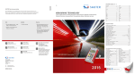
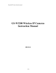
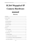
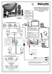
PHILIPS
Philips Consumer Communications
CUSTOMER SERVICES
SERVICE REPAIR SUPPORT
PCC/VY/691/E/XENIUMDB989LVL1/0025/MLD/MLD
Revision : 2
Author : Fabrice TANT
Approval : Jean Pierre HOLLANDE
PROCEDURE
Operational manager
Date : 19/06/2000
Page 1 out of 24
SERVICE MANUAL
Repair for Cellular Telephone
XENIUM DUAL BAND
LEVEL 1
-1PCC/VY/691/E/XENIUM989/0025/MLD/MLD
PHILIPS
Philips Consumer Communications
CUSTOMER SERVICES
SERVICE REPAIR SUPPORT
PCC/VY/691/E/XENIUMDB989LVL1/0025/MLD/MLD
Revision : 2
Author : Fabrice TANT
Approval : Jean Pierre HOLLANDE
PROCEDURE
Operational manager
Date : 19/06/2000
Page 2 out of 24
Service Manual
Last updates:
DATE
MODIFICATION
19/06/2000
CREATION
Revision 2 : 26/07/2000 - Modification of components list
CONTENTS
-2PCC/VY/691/E/XENIUM989/0025/MLD/MLD
PAGE
Page 23
PHILIPS
Philips Consumer Communications
CUSTOMER SERVICES
SERVICE REPAIR SUPPORT
Author : Fabrice TANT
Approval : Jean Pierre HOLLANDE
PCC/VY/691/E/XENIUMDB989LVL1/0025/MLD/MLD
Revision : 2
PROCEDURE
Operational manager
Date : 19/06/2000
Page 3 out of 24
1.0 PURPOSE--------------------------------------------------------------------------------------------------------------------------------------4
2.0 SCOPE------------------------------------------------------------------------------------------------------------------------------------------4
3.0 REFERENCE----------------------------------------------------------------------------------------------------------------------------------4
4.0 GLOSSARY/ACRONYM LIST-----------------------------------------------------------------------------------------------------------4
5.0 TEST EQUIPMENT AND TOOLS------------------------------------------------------------------------------------------------------4
6.0 TEST AND INSPECTION PLAN--------------------------------------------------------------------------------------------------------5
6.1 USER INTERFACE TEST................................................................................................................................................................5
6.2 RF TEST...................................................................................................................................................................................5
7.0 BEFORE STARTING-----------------------------------------------------------------------------------------------------------------------6
7.1 DESCRIPTION OF THE TRANSCEIVER................................................................................................................................................6
7.2 DESCRIPTION OF THE DISPLAY.......................................................................................................................................................7
7.3 USING THE CAROUSEL ...............................................................................................................................................................8
7.4 INSERTING THE MICRO-SIM CARD.............................................................................................................................................8
7.5 INSERTING ON THE BATTERY.........................................................................................................................................................9
7.6 REMOVING THE BATTERY..............................................................................................................................................................9
7.7 CHARGING THE BATTERY..............................................................................................................................................................9
8.0 TEST PROCEDURES---------------------------------------------------------------------------------------------------------------------10
8.1 INITIAL FUNCTIONAL CHECK FOR TCD989/J XENIUM..............................................................................................................10
8.2 RF TEST...............................................................................................................................................................................13
8.3 CHARGING IGN (IGNITION) – BATTERY......................................................................................................................................15
9.0 ASSEMBLY / DISMANTLEMENT PROCEDURES----------------------------------------------------------------------------15
9.1 DISMANTLEMENT......................................................................................................................................................................16
9.2 ASSEMBLY...............................................................................................................................................................................16
10.0 DEFAULTS SETTINGS-----------------------------------------------------------------------------------------------------------------16
10.1 RESET CUSTOMER PARAMETERS. ...............................................................................................................................................16
10.2 USE OF THE GSM STRING *#RSAV*# OR *#7728*#.............................................................................................................16
11.0 SOLUTIONS IN CASE OF PROBLEMS DURING THE TESTS-------------------------------------------------------------17
11.1 THE PHONE DOES NOT SWITCH ON..............................................................................................................................................17
11.2 CHARGE DOES NOT START OR NO DETECTION OF THE CHARGER.......................................................................................................17
11.3 THE DISPLAY SHOWS “NO SIM CARD. PLEASE INSERT YOUR SIM CARD.” OR “SIM FAILURE” .................................................17
11.4 DISPLAY PROBLEMS.................................................................................................................................................................18
11.5 BUZZER PROBLEMS..................................................................................................................................................................18
11.6 NO SOUND IN LOUDSPEAKER....................................................................................................................................................18
11.7 COMMUNICATION PROBLEMS.....................................................................................................................................................18
11.8 DEFECTIVE ANTENNA...............................................................................................................................................................18
11.9 KEYBOARD PROBLEMS.............................................................................................................................................................18
11.10 PROBLEMS TO SEND SMS MESSAGES.......................................................................................................................................18
12.0 RECOMMENDED PART LIST- TCD 989 XENIUM DB------------------------------------------------------------------------18
12.1 COMMON PARTS – OUT OF WARRANTY........................................................................................................................................18
-3PCC/VY/691/E/XENIUM989/0025/MLD/MLD
PHILIPS
Philips Consumer Communications
CUSTOMER SERVICES
SERVICE REPAIR SUPPORT
Author : Fabrice TANT
Approval : Jean Pierre HOLLANDE
PCC/VY/691/E/XENIUMDB989LVL1/0025/MLD/MLD
Revision : 2
PROCEDURE
Operational manager
Date : 19/06/2000
Page 4 out of 24
1.0 PURPOSE
This document establishes the functional test and inspection procedures for the first level service repair of the
XENIUM DB transceiver
2.0 SCOPE
The test plan is applicable to all levels of service repair of the XENIUM DB transceiver
3.0 REFERENCE
4.0 GLOSSARY/ACRONYM LIST
Window or Bezzel
SW
PN
CN
HW
ASC
NSC
Test SIM Card
Test SIM Card “SP”
Protective plastic over the LCD display
Software
Hardware Configuration of the Mobile
Matrix for Types of SW used on the different hardware
Hardware
Authorized Service Center
National Service Center
Used for functionality of PHILIPS Mobiles
SIM Card that is used to stimulate the user interface and allow radio tests
5.0 TEST EQUIPMENT AND TOOLS
Equipment / Tools
Production Test SIM Card
- Part No. : 4311 255 00781
Test SIM Card “SP”
- Part No. : 4311 255 00782
RF Cable
- Part No. : 941-555-1 (AMP).
Digital Multimeter
- Recommended Model : Fluke
Specification with current reading in mA.
Digital Radiocommunication Tester.
-4PCC/VY/691/E/XENIUM989/0025/MLD/MLD
PHILIPS
Philips Consumer Communications
CUSTOMER SERVICES
SERVICE REPAIR SUPPORT
Author : Fabrice TANT
Approval : Jean Pierre HOLLANDE
PCC/VY/691/E/XENIUMDB989LVL1/0025/MLD/MLD
Revision : 2
PROCEDURE
Operational manager
Date : 19/06/2000
Page 5 out of 24
6.0 TEST AND INSPECTION PLAN
The test plan is derived from the Product Test Reference for XENIUM DB.
6.1
User Interface Test
Use the Test SIM card “SP” / Production to test the transceiver as follows :
♦
♦
♦
♦
♦
♦
♦
♦
♦
♦
On/off Button
LCD Backlight
Keyboard Test
Buzzer Test
Audio Test
Antenna Test (levels 5 &10)
LCD
LED Test (On/Off)
IMEI
Tester Status/Eeprom Status
With a fast charger connected with the PRODUCT’s bottom connector, check the full scrolling from one mode to the
next when charging IGN (Ignition)-Battery.
6.2
RF Test
The radio test must be performed with a Digital Radio Test Set connected to the mobile RF connector with the
specific RF cable
-5PCC/VY/691/E/XENIUM989/0025/MLD/MLD
PHILIPS
Philips Consumer Communications
CUSTOMER SERVICES
SERVICE REPAIR SUPPORT
Author : Fabrice TANT
Approval : Jean Pierre HOLLANDE
Revision : 2
PROCEDURE
Operational manager
Description of the transceiver
-6PCC/VY/691/E/XENIUM989/0025/MLD/MLD
Date : 19/06/2000
Page 6 out of 24
7.0 BEFORE STARTING
7.1
PCC/VY/691/E/XENIUMDB989LVL1/0025/MLD/MLD
PHILIPS
Philips Consumer Communications
CUSTOMER SERVICES
SERVICE REPAIR SUPPORT
Author : Fabrice TANT
Approval : Jean Pierre HOLLANDE
Revision : 2
PROCEDURE
Operational manager
7.2
PCC/VY/691/E/XENIUMDB989LVL1/0025/MLD/MLD
Date : 19/06/2000
Page 7 out of 24
Description of the display
Indicates the Network on which
your phone is registered.
Clock : Indicates an hour.
Reception quality : The more bars shown
the better the reception.
Indicates the date
Battery level : The bars indicate the battery level
(4 Bars means full, no bars means recharging is
needed.)
-7PCC/VY/691/E/XENIUM989/0025/MLD/MLD
7.3
Using The Carousel
The carousel is a circular loop of icons displayed on the screen. These icons provide access to the different
menus and sub menus used to operate your phone.
7.4
7.4.1
Inserting the MICRO-SIM card
The mobile supports only the mini “plug-in” SIM card.
Push the metal retaining clip to the right and lift the cardholder. Slide in the SIM card between the retaining
clip and the plastic tongue with the cut corner of the card at the top left. Close the cardholder and push the
retaining clip to the left.
7.5
Inserting on the battery
7.5.1
Place the battery on the back of the phone (connectors downward, the top near the arrow inside the case).
7.5.2
Then push the battery into place in the direction of the antenna.
7.6
Removing the battery
7.6.1
Press the locking button located alongside the antenna while pushing the battery in the direction of the
arrow.
7.6.2
Remove battery.
7.7
Charging the battery
7.7.1
Plug the battery onto the transceiver
7.7.2
Plug the charger into the connector at the base of the transceiver.
7.7.3
7.7.4
Plug the transformer unit into the main AC power sockets.
The battery charge symbol indicates the state of the charge process :
•
•
Bars moving
Steady
-
means the battery is being charged
means the battery is fully charged
If the battery is totally discharged, the battery icon will show and start scrolling 2 to 3 minutes only after
connecting to the charger.
8.0 TEST PROCEDURES
8.1
8.1.1
8.1.2
8.1.3
Initial Functional check for TCD989/J XENIUM
Insert the Test Production Card into the SIM Reader at the back of the cellular phone and clip a charged
battery on the phone.
Press the «ON» button for 2 seconds at least and the LCD will show a message which contains information
of FA and 12NC. (see
Follow the instructions as mentioned below :
Step
1
2
3
4
Procedure
Press Key 1
Observation
Continue Buzzer signal
Press Key 1 again
Left corner displays 1
00
"LocalEffect"
" XX XX “
Press key 2
(Audio loop local effect)
Press key 2 again
Left corner displays 2
01
Press key 3
Audio loop test (Speak to
Mic and listen echo from
Speaker)
Press key 3 again.
"AUDIO xx xx xx ”
"EEP x xx xx xx ”
Press key 4 (LEDs Test)
Check for the Backlight
function in the same time.
Red and green LED blinking
Press key 4 again
Left corner displays 4
03
Left corner displays 3
02
5
6
7
8
9
Press Key 5
(Checkerboard test)
Checkerboard 1 pixel on
Press Key 5 again
Left corner displays 5
04
Press Key 6
(Inverted Checkerboard)
Checkerboard 2 pixel on
Press Key 6 again
Left corner displays 6
05
Press Key 7
All pixels and hard icons on
Press key 7 again
Left corner displays 7
06
Press key 8 (Eeprom
Status)
"EEPROM STAT” (Must be Good)
H-XXXX-XXXX (Eeprom Status)
L-XXXXXX-XX
SimLk XXXXX (Sim lock Status)
Press Key 8 again
Left corner display 8
07
Press Key 9 Product
information
Compare information with
label printed on back case
“PROD INFO”
“XXXXXXXXX” (Product 12NC)
“XXXXXXXX” (PN Number)
VY made in Le Mans
SA made in Singapore
EO made in Shenzhen
10
Press key 9 again
Left corner displays 9
08
Press key 0
“ADC MEASURES”
“XXXX XXXX”
“XXXX XXXX”
11
Press key 0 again
Left corner displays 0
09
Press * (IMEI Test)
Compare IMEI with label
printed on back case
"IMEI TEST"
" XXXXXX/ 50 / XXXXXXX" for (TCD989/J)
06 made in Singapore
50 made in Le-Mans
69 made in China
Press * again
Left corner displays *
12
12
13
14
15
16
17
Press # (FA Status)
"FA/12NC”
FA GOOD (Must be good) X
XXXXXXXXXXX (12NC)
Press # again
Left corner displays #
13
Key without Test
Press C
Press C again
Left corner displays C
14
Go to the UP with the
Scanswitch
(Melody Test)
User Melody
Go to the UP again
Left corner displays 0A
Go to the DOWN with the
Scanswitch
(Memory Test)
“MEMORY TEST”
“XXXXXXXX”
“XXXXXXXX”
“RAM OK”
Go to the DOWN again
Left corner displays 0B
Press the Scanswitch
“PAGE”
“SELECTION”
“XX”
Press the Scanswitch
Left corner display OK
0E
Press Green button
“ MANUAL TEST”
“
GOOD
“
Press Green button again
Left corner displays
0F
18
Press Red button
“ MANUAL TEST”
“
BAD
“
Press Red button again
Left corner displays
10
8.1.4
If any of the step failed functional, refer to Chapter 10.
8.1.5
Perform visual check on battery connectors, car kit connectors and casing.
If corrosion or deform send to NSC for repair.
8.1.6
If the product is good, it is considered as a NFF product.
All the NFF products must be directly returned to the customer.
8.2
RF TEST
8.2.1
The Test SIM Card “SP” must be inserted into the phone before starting the tests.
8.2.2
Set the equipment as shown on the picture in chapter 6.2.
8.2.3
Set in the offset field of the radio tester a – 0.3 dBm lose for GSM Test
8.2.4
The following operations must be done:
-
8.2.5
Synchronization/Registration
Call set up from the mobile
Voice loopback ( to check the sound quality)
Call release
Call set up from tester
Call release from tester
The following parameters must be checked in TCH loop mode :
Emission parameters :
-
Power level
RMS phase error
Peak phase error
Frequency error
Power ramping
Reception parameters :
-
Rx level
Rx quality
BER (Byte Error Rate)
FER (Frequency Error Rate)
Generally the test sequences built inside the testers will be used to check the mobile. You must assess that the test
sequences limits comply with the standard specifications.
8.2.6
GSM Specification (900 Mhz)
Test Parameters
EMISSION
Phase Error RMS
Phase Error Peak
Frequency Error
Power Ramping
Modulation
Switching Transients
Power Reading
Channel
Level
Standard Specification
1, 62, 124
1, 62, 124
1, 62, 124
1, 62, 124
1, 62, 124
1, 62, 124
5, 10, 15
5, 10, 15
5, 10, 15
5, 10, 15
5, 10, 15
5, 10, 15
0 to 5 degrees
-20 to +20 degrees
-90 Hz to +90 Hz
Mask
Mask
Mask
Output Power Average 1, 62, 124
1, 62, 124
1, 62, 124
Level 15
Level 10
Level 5
11.2 dBm to 14.8 dBm
21.2 dBm to 24.8 dBm
31 dBm to 34.1 dBm
RECEPTION
Rx Level
Rx Level
Rx Level
1, 62, 124
1, 62, 124
1, 62, 124
-83 dBm
-60 dBm
-40 dBm
+/-2.5 dBm
+/-2.5 dBm
+/-2.5 dBm
TCH LOOP
SENSITIVITY
BER
FER
BER
1, 62, 124
1, 62, 124
1, 62, 124
-85 dBm
-85 dBm
-102 dBm
0%
0%
< 2.44%
FER
BER
FER
1, 62, 124
1, 62, 124
1, 62, 124
-102 dBm
-103 dBm
-103 dBm
0%
< 2.44%
0%
If a phone is out of the specifications, it must be sent to the Repair Center.
8.2.7
PCN Specification (1800 Mhz)
Test Parameters
EMMISSION
Phase error RMS
Channel
level
Standard Specification
512, 635, 760,885
0,5,10
0 to 5 degree
0,5,10
0,5,10
0,5,10
0,5,10
0,5,10
-20 to +20 degree
-180 Hz to + 180 Hz
Mask
Mask
Mask
level 0
level 10
level 19
30 +/- 2 dbm
10 +/- 4.0 dbm
0 +/- 5.0 dbm
-100dbm
-100dbm
-80dbm
-80dbm
-60dbm
-60dbm
8 to 13
0 to 1
28 to 33
0 to 1
48 to 53
0 to 1
Phase error Peak
Frequency Error
Power Ramping
Modulation
Switching Transcients
Power reading
Output Power
RECEPTION
Rx Level
Rx Qual
Rx Level
Rx Qual
Rx Level
Rx Qual
TCH LOOP
512, 635, 760,885
512, 635, 760,885
SENSITIVITY
BER at -85dbm
FER at -85dbm
BER at -103dbm
512,635,760,885
0%
0%
2.44%
FER at -103dbm
0%
If a phone is out of the specifications, it must be sent to the Repair Center.
8.3
8.3.1
Charging IGN (Ignition) – Battery
Plug the connector of the charger into the round socket set at the base of the transceiver.
The battery symbol should indicate the state of the charge process :
• Bars moving
- means the battery is being charged.
• Steady
- means the battery is fully charged.
If the battery is totally discharged, the battery icon will start scrolling 2 to 3 minutes only
after being connected to charger.
8.3.2
Remove the charger by unplugging the connector from the round socket at the base of the transceiver.
8.3.3
Remove the battery.
8.3.4
Lift the bottom left side of Production Test SIM Card with a tweezer.
8.3.5
Gently slide the card out away from the grooves of the Product
9.0
ASSEMBLY / DISMANTLEMENT PROCEDURES
During dismantlement and assembly operations, an antistatic bracelet must be used.
9.1
Dismantlement
9.1.1
9.1.2
9.1.3
9.2
Unscrew the ANTENNA
Take the product, remove BATTERY
Remove the SIM card
Assembly
9.2.1
9.2.2
9.2.3
Check the REAR HOUSING on the product
Check the LABEL on the back
Screw the ANTENNA
10.0DEFAULTS SETTINGS
10.1 Reset customer parameters.
To reset customer parameters, it must use a GSM String. This Gsm String is
*#RSAV*# or *#7728*#.
So, the defaults settings of the manufacturer are actived.
10.2 Use of the GSM string *#RSAV*# or *#7728*#.
Procedure to follow :
-
Turn on the mobile (a SP SIM card is not necessary).
Enter the Gsm String *#RSAV*# or *#7728*#.
You can see “Reset” but the customer parameters are not reset yet.
Turn off the mobile.
When you will turn on, the defaults settings will be actived.
11.0SOLUTIONS IN CASE OF PROBLEMS DURING THE TESTS
If for any reasons the phone needs to be disassembled (on level 2 only) to fix a defect detected during the test
procedure, a complete functional test and a RF test must be done.
11.1 The phone does not switch on.
- Check the tactile feeling of the “ON/OFF” button.
- Remove the battery. Check that both the contacts of the phone and those of the battery are not damaged.
- Clean the contacts.
- Plug the battery again, making sure that it is securely fitted. Charge the mobile until the icon has stopped
flashing.
Then unplug from the charger and attempt to switch the mobile on.
If it still does not switch on, send the mobile for repair.
11.2 Charge does not start or no detection of the charger.
- Check the charger contacts for dust or missing pins.
- Check the mobile connector.
- Remove the battery. Check that both the contacts of the phone and those of the battery are not damaged.
- Check the charger individually with a reference mobile. If the charger works properly try to charge the
customer mobile with a reference battery.
If neither of the battery and the charger can be incriminated, send the mobile for repair.
11.3 The display shows “No SIM card. Please insert your SIM card.” or “SIM FAILURE”
- If the SIM card cannot be inserted, check for any foreign part and try to remove it.
- Check the SIM Card connector. All the contacts must be at the same level. Make sure that there is no dust
on the connector contacts and the SIM card contacts.
- If the test SIM card can be detected but the message “SIM Failure” remains on the customer’s card, his
card must be damaged. Ask him to contact his network operator.
Otherwise send the mobile for repair
11.4 Display problems
Contrast, icons and matrix of the display can be checked with the test SIM card by pressing keys ”5”, “6” and
“7” .
If everything works in test configuration it then means that a phone setting is disabled or does not suit well. It
can be solved in the phone menu.
Otherwise send the mobile for repair
11.5 Buzzer problems
Buzzer tone can be checked with the test SIM card by pressing key “1” and “2”.
- If it does not sound properly send the mobile for repair.
11.6 No sound in Loudspeaker
The sound from the loudspeaker can be checked with the test SIM card by pressing key “3”.
- Check the microphone and the earpiece, If the failure cannot be found out, send the mobile for repair.
11.7 Communication problems
- Sound quality can be checked in audio loop test (sound distortion, whistling, echo, …)
- If the mobile passes the radio tests successfully, we can assume that the phone works properly. The
customer must check the coverage area of his network operator or that he does not use the phone in a radio
shadow (outside the coverage area, in a tunnel or between tall buildings, …)
- If the mobile does not pass the radio tests, send the mobile for repair.
11.8 Defective antenna
- If the antenna is broken or curved => replace it
11.9 Keyboard problems
-The keyboard can be checked with the test SIM card.
- If a key or a row does not respond, check the keyboard.
11.10 Problems to send SMS messages
Check the Center number. It may be empty or wrong.
12.0RECOMMENDED PART LIST- TCD 989 XENIUM DB
12.1 Common parts – out of warranty
REFERENCE
DESIGNATION
POSITION
REPAIR LEVEL
4311 257 61141
4311 258 72846
4311 258 75075
3122 427 20946
3122 427 21206
Antenna ass’y X16 DB
Battery Slim 800mAh (Li-on)
Vibra Battery (900 mAh Li-on)
Fast Charger Europe
Fast Charger UK
ANNEXE 1
0906
-
1
1
1
1
1
Each returned product must have an IRIS code to identify the failure.