1
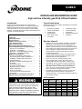
9-200.5 November, 2015 DESIGN AND ENGINEERING GUIDE high and low intensity gas-fired infrared heaters Introduction Typical Applications Modine gas-fired infrared heaters for comfort heating applications can be used alone or in combination with other Modine heating equipment such as gas-fired unit heaters, make-up air units, etc. to provide superior comfort heating solutions. This guide will provide a basic understanding of the principles of using infrared heat. The following are typical examples of buildings that can benefit from infrared heating: TABLE OF CONTENTS PAGE Introduction…………………………………………… Typical Applications………..……………………….. Why Use Infrared.................................................... SI (Metric) Conversion Factors…………….……… Types of Heat Transfer………..…….…………...…. Types of Infrared Heaters………….………….……. Understanding Heat Spread/Distribution….…….. Infrared Heater Selection Procedure and Data Clearance to Combustibles………...……………… Application – Spot Heating………………………… Application – Partial Building/Area Heating……… Application – Total Building Heating……………… Additional Considerations Mounting Height/Building Obstructions………….. Low-Intensity Tube Length Considerations….….. Availability of Utilities (Gas and Electric)……..….. Venting/Ventilation…………………………………. Multiple Low Voltage Heaters/Single Stat…….…. Humidistat…………………………………………… Thermostat Location……………………………….. Contaminated Atmospheres……………………..... Negative Pressure in Space……………………..... Outdoor Applications………………………………. Duration of Operation…………………………….... Low-Intensity Tube System Expansion………….. Accessories…………………………………………. Typical Selection Considerations Summary…..... Performance Data (Total Building Heating Only)…….... 1 1 1 1 2 2 3 4 6 7 8 9 9 9 9 10 10 10 10 10 10 10 10 10 11 12 Manufacturing facilities Vehicle repair facilities Loading docks Aircraft hangars Indoor tennis courts Car washes Golf driving ranges Covered walkways Fire stations Stadium seating areas Vestibules Why Use Infrared? Significant energy cost reduction potential in spot heating applications. Conventional warm air heating systems must warm the air and move it across the people to be heated. If just a few workers are in a small area of a large open building, this would require heating large volumes of air to accomplish a suitable comfort level. However, infrared heaters in that area would heat only objects, including those workers. Infrared installations may actually use lower thermostat settings as the radiant heat reaches the worker more effectively than forced air applications. There is no air mover, reducing electricity costs. There is better worker comfort, since there are no uncomfortable drafts or annoying fan or blower noise. Temperature recovery is quick if cold air is introduced from open doors or windows. A forced air heater must heat larger volumes of cold air before occupants feel warm. However, an infrared heater supplies immediate heat to the workers and objects in the space. The ability to control heating in zones is very easy with infrared heaters because infrared is well-suited for heating small areas. This would be difficult and inefficient with forced air heaters. SI Conversion Improper installation, adjustment, alteration, service, or maintenance can cause property damage, injury, or death, and could cause exposure to substances which have been determined by various state agencies to cause cancer, birth defects, or other reproductive harm. Read the installation, operating and maintenance instructions thoroughly before installing or servicing this equipment. To Convert "W.C. °F Btu 3 Btu/ft Btu/hr 3 ft /hr 3 ft /hr 3 ft /min 3 ft /min Multiply By 0.249 (°F-32)x5/9 1.06 37.3 0.000293 0.000472 0.00000787 0.0283 0.000472 To Obtain kPa °C kJ 3 kJ/m kW 3 m /min 3 m /s 3 m /min 3 m /s To Convert feet Gal/Hr. Gal/Hr. gallons HP inches pound psig psig Multiply By 0.305 0.00379 3.79 3.79 746 25.4 0.454 6.89 27.7 To Obtain m 3 m /hr l/hr l W mm kg kPa "W.C. Heat Transfer and Infrared Heater Basics Types of Heat Transfer Types of Infrared Heaters Infrared heaters primarily transfer heat directly through radiation. However, infrared heaters indirectly cause conduction and convection heat transfer within a heating application. The following is a summary of the different types of heat transfer: Modine offers two types of infrared heaters; high-intensity and low-intensity. Both are certified for commercial and industrial applications only. The following is a brief description of each type of infrared heater: Radiation This is the transmission of heat through a space by infrared energy rays emitted from a hot surface. The infrared energy is transmitted through space and heats only the objects the energy strikes. The energy can actually pass through a vacuum and remain virtually unchanged. A familiar example is the Sun, which radiates energy to objects such as the Earth. When a person is outside on a sunny day, the person feels the warmth of the Sun. If a cloud passes over, the person feels cooler. Although the air temperature doesn’t change, the amount of radiant energy reaching that person is reduced since the water droplets of the cloud absorbed some energy. High Intensity Units utilize a diamond faced ceramic tile burner for maximum heat transfer, housed in a rugged, aluminized steel frame. The flame burns on the outer surface of the tile(s) with the infrared energy efficiently directed by a polished aluminum reflector mounted on the aluminized steel frame. Source temperatures can range from 1800°F to 2200°F. The units are certified for indoor use only and operate unvented. A minimum positive air displacement of 4 CFM per 1000 Btu/hr input for natural gas or 5 CFM per 1000 Btu/hr input for propane gas is required for proper ventilation. Figure 2.1 – High Intensity Infrared Heater In the case of infrared heaters, the heat is radiated from the heater to objects in the space such as storage racks, machines, the floor, and people. These objects, in turn, radiate the heat gained from the infrared heater. Conduction This is the transmission of heat through solid objects by the exchange of energy from warmer molecules to cooler molecules. An example is a pot on a stove. Even though the flame does not directly heat the handle, it gets hot because heat from the bottom of the pot is transferred to the cooler handle. In the case of the infrared heating application, the objects in the space conduct heat gained through radiation from the infrared heaters. For example, the warmed floor conducts heat through the shoes of a person standing on the floor, warming the person’s feet. Convection This is the transmission of heat through gases or liquids by the movement of masses of the gases or liquids. An example is air moving across a fin-tube heater. As the fin-tube element heats the surrounding air, the air becomes less dense and rises. Cooler air takes its place surrounding the heating element and is heated. This process continues, heating the air in the room. In the case of the infrared heating application, the warmed objects, such as the floor and storage racks, heat the air surrounding the objects. Low Intensity Low-intensity units utilize an aluminized steel heat exchanger tube with a polished aluminum reflector that efficiently directs infrared energy. The burner is mounted at one end opening of the tube and exhausts at the other end opening. Tube systems are available in either straight or U-tube configurations. Source temperatures near the burner end of the tube system can reach 1200°F. Units are available as pressurized type systems, which provide a power exhauster mounted at the same end as the burner to force the products of combustion through the tube. The units operate vented. Units are for indoor or outdoor applications. Figure 2.2 – Low Intensity Infrared Heater 2 9-200.5 Understanding Heat Spread and Throw/Distribution Before selection occurs, a solid understanding of the infrared heater heat spread/distribution is required to avoid potential misapplications of the equipment. This section provides the basic information to gain this understanding. Low Intensity Heat Spread/Distribution High Intensity Heat Spread/Throw Heat spread (width), as shown in Figure 3.1 is dependant on the mounting height and relatively unaffected by the mounting angle. The spread at floor level is approximately twice the mounting height. However, someone occupying the edge of that space will feel minimal heat. To cover an entire area up to 5 feet high (shoulder level for the average worker), the mounting height should be approximately 5 feet above half the distance of the desired width. For example, if the shoulder height area width is to be 40 feet wide, the mounting height should be approximately 25 feet above the floor (5 feet + ½ x 40 feet = 25 feet). The actual floor level spread will be approximately 50 feet, but the radiated infrared heat is negligible at the edge of that area. Heat spread (width), as shown in Figure 3.3 is dependant on both the mounting height and mounting angle. The spread at floor level for a unit mounted at 0° is roughly twice the mounting height. However, someone occupying the edge of that space will feel very little heat. To cover an entire area up to 5 feet high (shoulder level for the average worker), the mounting height should be approximately 5 feet above half the distance of the desired width. For example, if the shoulder height area width is to be 30 feet wide, the mounting height should be approximately 20 feet above the floor (5 feet + ½ x 30 feet = 20 feet). Note that the actual floor level spread will be approximately 40 feet, but the infrared heat is negligible at the edge of that area. Figure 3.3 – Low Intensity Heat Spread Width Figure 3.1 – High Intensity Heat Spread Width Height Height Total Spread Spread Width 5’ Spread Width = (Height – 5ft) x 2 Heat distribution (throw) is dependent on both the mounting height and the mounting angle. At a 10° mounting angle, the heat throw at a height of 5 feet will be approximately ½ x (the mounting height – 5 feet) in one direction and 1 ½ x (the mounting height – 5 feet in the other direction). For example, if the unit is mounted at 25 feet above the floor, then the spread will be 25 feet – 5 feet = 20 feet x ½ = 10 feet in one direction and 25 feet – 5 feet = 20 feet x 1 ½ = 30 feet in the other direction. The total throw would be 10 feet + 30 feet = 40 feet. Selection of mounting angle is influenced by the application, which will be discussed in a later section. Figure 3.2 – High Intensity Heat Distribution/Throw Total Spread = (Height – 5ft) x 2 [ 0° mounting angle] Total Spread = (Height – 5ft) x 4 [45° mounting angle] Heat distribution is dependent on the type of tube system used (straight versus U-tube) and the length. Heat intensity along the length of the tube system varies considerably. A solid understanding of this distribution is key to ensuring that the equipment is properly specified for the application. Misunderstanding is the number one cause of complaints of insufficient heat. The first step toward understanding the distribution of radiant heat is gaining an appreciation for the significant effect that temperature has on radiant intensity. The basic equation for calculating radiant intensity is: R (Watts/in2) = x σ x (Temp)4 , where: = Emissivity of the emitter (tube system) σ = Stefan-Boltzmann Constant Temp = Temperature difference between the emitter (tube system) and the absorber (people) H 1.5H @ 10° 3.5H @ 35° 5’ 0.5H @ 10° 0.0H @ 35° Without going into the theory behind the calculations, the important item to note is that the radiant intensity varies by the absolute temperature difference raised to the 4th power (multiplied by itself 4 times), which tells us that temperature has a significant effect on radiant intensity. Since the tube system is a long heat exchanger, it is losing heat along its 9-200.5 3 Understanding Heat Spread and Throw/Distribution Low Intensity Heat Spread/Distribution (continued) length. The result is that tube temperatures start around 1000 to 1200°F on the burner end and fall to about 350 to 400°F on the opposite end (the vent end). For comfort radiant heating, once the tube temperature falls along its length to approximately 600°F and below, the radiant heat felt by occupants begins to decrease significantly. The tube system still provides sensible heat to the space, which is important for total building heating applications, but for spot and partial area heating, these temperatures would not provide adequate comfort levels. The following typical tube temperature profiles will help in the discussion toward understanding which type of tube system configuration is appropriate with different applications. 60 Foot Straight Tube System Example The following figure shows a typical tube system temperature profile for a 60 foot straight tube system. The temperatures are adequate for comfort radiant heating to just over 40 feet. Beyond that distance, radiant heating will be negligible, as the temperature falls below 600°F. Figure 4.1 – 60 Ft Straight Tube Temperature Distribution Approximate Tube Temp Across Tube System 60 Foot Straight Tube 1000 °F 800 600 400 Understanding these temperature distributions and resulting effects on comfort heating will be important as application specific examples are covered in later sections of this guide. It is important to note that the recommended mounting heights shown in the Performance Data are based on those units providing comfort heating levels when mounted within the ranges shown. From the previous discussion, it can be seen that the heat spread and throw will increase as the mounting height is increased. As the height specified changes, it is important to select the unit ratings that reflect that height. Mounting a unit higher than recommended can result in complaints of low heat output. Mounting a unit too low can result in complaints of too much heat. While the coverage has changed, the infrared output has remained constant, resulting in an increase or decrease in the intensity of the infrared energy over the given area. It is also important to understand that high intensity units generally have to be mounted higher than low intensity units. The following table summarizes this typical data. Table 4.1 Typical Mounting Heights (ft) for Comfort Heating Input Rating (MBH) High Intensity Low Intensity 30 N/A 10 – 13 50 to 60 13 – 20 10 - 12 75 to 100 15 – 24 12 - 14 120 to 150 16 – 25 15 - 22 160 N/A 17 – 29 175 N/A 18 - 28 200 19 - 31 20 - 30 200 0 10 20 30 40 50 60 Feet from Burner Infrared Heater Selection Procedure Temperatures shown are for example purposes only. Actual results may vary based on input rating, gas heat value, altitude, etc. 60 Foot U-Tube System Example The following figure shows a typical 60 foot U-tube system temperature profile (30 feet out to a 180° U-tube and 30 feet back). The temperatures are adequate for comfort radiant heating over the entire 30 foot length, since the temperatures are above 600°F. Like the straight tube system, radiant heating will be negligible over the last 20 feet of the tube system, however since that portion is running next to the first 20 feet of the tube system where temperatures are the highest, there is no adverse effect on radiant heating output. Figure 4.2 – 60 Ft U-Tube Temperature Distribution Approximate Tube Temp Across Tube System 60 Foot U-Tube 900 °F Clearance to Combustibles Clearance to combustibles is also a critical in selection of the unit. Please refer the unit Installation and Service Manual for complete details. Care must be taken to ensure that the units have adequate clearance around them so that combustible materials will not ignite or be damaged. As a guideline, certified minimum distance to combustible material is based on the combustible material surface not exceeding 90˚F above ambient (160˚F typical). This does not apply to just wood, drywall, etc., but some other commonly encountered items as well. Below are some examples, 1000 800 700 600 0 5 10 15 20 Feet from Burner 25 30 35 Temperatures shown are for example purposes only. Actual results may vary based on input rating, gas heat value, altitude, etc. 4 The proper selection of heaters in the design and layout of an infrared heating system is determined by a number of factors, but primarily by the following: 9-200.5 Vehicles parked below the heater. Sprinkler heads near the unit. Storage of combustible materials. This is sometimes overlooked and requires additional action on the part of the building owner/operator. In these locations, signs shall be clearly posted in the vicinity of the heater where readily apparent to material handlers to indicate the maximum permissible stacking height to maintain required clearances from the heater. See Figure 5.2 on the following page for additional details. Infrared Heater Selection Procedure – General 30-60 90-100 120-150 160-200 Table 5.1 – High Intensity Minimum Clearances to Combustibles (inches) SIDE OF HEATER 30 36 46 48 BACK OF HEATER TOP OF HEATER: 30 30 33 33 - Mounted 0-29° 60 62 64 68 - Mounted 30° only 48 50 58 68 - w/ Optional Heat Deflector 0-29° 34 38 N/A N/A - w/ Optional Heat Deflector 30° 34 38 N/A N/A Model Sizes Table 5.2 – Low Intensity Clearance to Combustibles Model Model Size A B C Series (MBH) IPT 50/60 75/100/125 150/175/200 9 9 12 54 76 106 20 24 38 Clearance to each end and above the U-Tube is 12 inches. Refer to the figures below. Figure 5.3 – Low Intensity Clearance to Combustibles Straight Tube Systems BELOW HEATER: - Standard Reflector 80 105 125 140 - w/Optional Parabolic Reflector 110 135 165 180 Refer to the figures below. Figure 5.1 – High Intensity Clearance to Combustibles Figure 5.4 – Low Intensity Clearance to Combustibles UTube Systems and U-Tube Figure 5.2 – Clearance to Stored/Stacked Materials 12” 12” 9-200.5 5 Infrared Heater Selection Procedure – Spot Heating Table 6.1 – Spot Heater Selection Table Application/Intended Operation of the System MHR100 Spot Heating Spot heating is used for individual workers who require the replacement of body heat loss where heating the surrounding area with forced air heat would not be practical. Infrared heat is well suited for this application, as the objects (people) would be heated and not the surrounding air. The heat required for individual comfort varies with environmental, physiological, and even psychological variables. Activity level, room temperature, relative air movement, humidity, and clothing all contribute to the comfort or discomfort of an individual. It is also psychological since one person’s perception of comfort is different than another person’s perception. There are various engineering principles and calculations that can be used to derive appropriate ratings for comfort spot heating. However, there is still the psychological factor that differs between people that cannot be easily accounted for in equations. In lieu of working through complex formulas, the following table can be used to approximate the model number required to meet the conditions of the application. For spot heating, high intensity heaters are the best choice. It is preferable to use two heaters for heating people to ensure both the front and back sides are comfortable. If it is impractical to use two heaters, it is usually advisable to use one heater of the next higher model at an increased mounting height, provided mounting height restrictions do not eliminate this option. Table 6.1 shows three different ambient conditions; Cold/Drafty Air, Average/Calm Air, and Warm/Still Air. The occupant of the space should make the determination of the ambient conditions, based on personal perception. Once ambient conditions are determined, heater ratings can be determined based on the available mounting height. For areas requiring larger coverage, units with higher ratings can be used, provided the available mounting heights are adequate. Note that the table assumes a 30° mounting angle. Mounting angles less than 30° are not advisable since the heater would then need to be mounted more directly overhead of the person. In this situation, excessive infrared energy would be directed at the head of the person, causing discomfort and uneven heating over the surface of his/her body. 6 9-200.5 MHR120 MHR160 & 200 Approximate Area of Coverage The following section will provide specific background information necessary to satisfy each of these applications. MHR 60 Recommended Horizontal Distance to Person MHR 30 Recommended Mounting Height Spot heating – Used for heating only small areas, such as a loading dock or a single person work cell. Excellent application for infrared. Partial building heating – Used to heat sections of a building such as an assembly line or office section located in an open area of a warehouse. Excellent application for infrared. Total building heating – Used to heat the entire building. This is a fair application for infrared, but other equipment should also be considered as an alternate. Ambient Conditions Model Infrared systems can serve three basic applications: Cold/Drafty Air Average Warm/Still Air Cold/Drafty Air Average Warm/Still Air Cold/Drafty Air Average Warm/Still Air Cold/Drafty Air Average Warm/Still Air Cold/Drafty Air Average Warm/Still Air 8'-10' 10'-12' 12'-14' 12'-14' 14'-16' 16'-20' 18'-20' 20'-22' 22'-26' 22'-26' 26'-30' 30'-36' 24'-28' 28'-32' 32'-36' 4'-5' 5'-6' 6'-7' 6'-7' 7'-8' 8'-9' 9'-10' 10'-11' 11'-12' 11'-12' 12'-13' 13'-14' 12'-14' 14'-16' 16'-20' 10' x 10' 12' x 12' 14' x 14' 14' x 14' 16' x 16' 20' x 20' 20' x 20' 22' x 22' 26' x 26' 26' x 26' 30' x 30' 36' x 36' 28' x 28' 32' x 32' 36' x 36' Note that these are recommended values only and may need to be adjusted to meet requirements of the actual installation. A 30° mounting angle is required. Figure 6.1 – Typical Spot Heater Mounting (Single Heater Shown) 30° Low Intensity Unit for Spot Heating While high intensity units are the best option for spot heating applications, low intensity units can be used but should be kept to 20 or 30 foot long tube systems in a U-tube configuration. Mounting angle should be 45°, ideally with two units, one on each side of the person. Infrared Heater Selection Procedure – Partial Building/Area Heating Partial Building Heating Example 1 – Qty (1) 60 Foot Straight Tube System Approximate Tube Temp Across Tube System 60 Foot Straight Tube 1000 800 °F Partial building or area heating is used for smaller areas within a building that are larger than a spot heating application. Examples include an assembly line or an open office/service counter area in the middle of a large open warehouse type building. These areas all have people moving about in a small area that need to be kept warm without heating the remainder of the building to comfort heating levels. 600 400 Typically, low intensity units are the ideal choice for partial area heating. Critical to a proper selection/layout is having a clear understanding of the heat spread/distribution across the length of the tube system. This was discussed in an earlier section, but to better illustrate the differences that tube lengths and configurations make in an application, we will look at an imaginary fish packing company that has a 60 foot long fish packaging line. At one end, an employee is loading frozen fish onto a conveyor. In the middle, an employee is packaging the frozen fish for shipment. At the far end, an employee is taking the boxes and loading in a refrigerated trailer on the dock. Example 2 The use of two 30 foot straight tube systems will help significantly over the configuration shown in Example 1. The employees on both ends will be blanketed with radiant heat. However, remember from the discussion on heat spread/distribution, that the tube end opposite the burner will be about 350 to 400°F. The person in the middle of the line may not receive an ideal level of radiant heat, although they may get some heat from adjacent warmer sections. This is a good layout, but comfort could be enhanced. 0 10 20 30 40 50 60 Feet from Burner It’s andhere, warmI It’sso sonice warm atcould work, handle I could handle cold cold fish all day. agree, it’s I I II agree, it’sso sonice, nice, feel feelproductive. so productive. It’s soso freaking cold It’s cold here, over that thathere, heater isheater junk. above is junk. fish all day. Example 2 – Qty (2) 30 Foot Straight Tube Systems Approximate Tube Temp Across Tube System Qty (2) - 30 Foot Straight Tubes 1000 800 °F Example 1 A common mistake is to layout the heating system as a single 60 foot straight tube system. While it will be physically be located over the entire packaging line, remember from the heat spread/distribution discussion that when the tube temperature falls below approximately 600°F, radiant heat will be negligible. The first two people on the line will feel comfortable, but the person loading the trailer will feel very little heat. One option would be to place high intensity heater(s) in that area and treat it as a spot heating application within a partial area heating application. 200 600 400 200 0 10 20 30 40 50 60 Feet from Burner It’s andhere, warmI It’sso sonice warm atcould work, handle I could handle cold cold fish all day. I’m happy It’s soreally freaking coldmy employer enough over here,cares that heater to keep me warm. above is junk. I agree, soI nice, It’s not it’s bad, wishI it feel wasproductive. a little warmer. fish all day. Example 3 – (2) 60 Foot U-Tube Systems Example 3 The use of two 60 foot U-tube systems is the ideal solution for ensuring ideal radiant heat across the entire packaging line. Approximate Tube Temp Across Tube System Qty (2) - 60 Foot U-Tubes 1000 Summary: Example 1 – Bad application, occupant complaints on one end of the assembly line. Example 2 – A good layout, although temperature may be a bit low in the middle of the assembly line. Example 3 – A great layout with even heat distribution across the entire assembly line. °F 800 600 400 200 0 10 20 30 40 50 60 Feet from Burner It’s andhere, warmI It’sso sonice warm atcould work, handle I could handle cold cold fish all day. fish all day. agree, it’s I I II agree, it’sso sonice, nice, feel feelproductive. so productive. happy It’sI’m soreally freaking coldmy employer enough over here, cares that heater above is junk. to keep me warm. Choosing between Example 2 and Example 3 as a solution comes down to the cost/benefit ratio of comfort level versus equipment price. 9-200.5 7 Infrared Heater Selection Procedure – Total Building Heating Total Building Heating Total building heating applications involve replacing the building heat loss with at least the same amount of heat, placed near the areas of greatest heat loss. Total building heating applications with infrared are best accomplished using low intensity tube heaters. However, Modine offers a number of different heating equipment options for building heating, so all options should be considered. This guide will only focus on an infrared heater layout. The selection process for infrared in a total building heating application is more of an art than a science. One must not only know the heat loss of the building and the dimensions, but other characteristics such as the available mounting height, clearance to combustibles, and building layout which includes the shape of the area, location of utilities, physical interference from equipment such as lights or overhead cranes, etc. The selection/layout process is outlined below. Determine Available Ratings After the type of infrared heater to be used has been determined, high-intensity, low-intensity, or a combination of both, available ratings are determined based on the mounting height and required clearances to combustibles as indicated in the Performance Data tables on page 12. Example 1: A building has a ceiling height of 18 feet. Low intensity units are to be used. What are the available unit sizes that should be considered in the layout? From the Performance Data, the applicable unit ratings are 125,000 Btu/hr for mounting between 15 to 22 feet, 150,000 Btu/hr for mounting between 15 to 25 feet, and 175,000 Btu/hr for mounting between 18 to 28 feet. Each requires a minimum of 12" clearance to combustibles from the top. Based on the required clearance, the mounting height should not exceed 17 feet (i.e. ceiling height of 18 feet – 12” = 17 feet). This would make the 175,000 Btu/hr unit a less likely choice since it is recommended to be mounted above that height. While it makes sense to place the heaters along the perimeter, if the distance between parallel walls exceeds 100', it is best to use a combination approach of perimeter and row heating. The heater capacity along the perimeter should be at least 80% of the total system capacity with the remaining maximum 20% of the total system capacity located in parallel rows toward the center of the building. The center rows are used to compensate for the roof heat losses. Example 2: Expanding on Example 1, the building is 200' long x 160' wide with a calculated heat loss of 1,600,000 Btu/hr. Example 1 determined that units rated 125,000 or 150,000 Btu/hr should be considered. Which will work best? If the building heat loss is 1,600,000 Btu/hr, the number of 125,000 Btu/hr units required would be 13 (1,600,000 / 125,000 = 12.8 13 units). For 150,000 Btu/hr rated units, the quantity required would be 11 units. Reviewing the figure for Example 2 on the following page, there will be 3 units required to cover each of the 200’ long walls (using 60 foot straight tube systems). Since the distance between parallel walls exceeds 100', it is best to use a combination of perimeter and row heating. Adding a third row in the center will require another 3 units. So far, this is 9 units total, and the 160’ long ends of the building need to be covered. Given the distance, the minimum tube length should be 60’ with 2 systems required on each end. The choices at this point are: Use (13) 150,000 Btu/hr units with 60’ straight tube systems. Total input will be 1,950,000 Btu/hr. Use (13) 125,000 Btu/hr units with 60’ straight tube systems. Total input will be 1,625,000 Btu/hr. Use (13) units that are a combination of 125,000 and 150,000 Btu/hr units. Total input will be based on the mix of the ratings selected. All three choices are acceptable. The use of (13) 125,000 Btu/hr units may have trouble maintaining design temperature on the coldest days that fall below the winter design temperature. The 150,000 Btu/hr units will normally accommodate even the coldest days, but may be oversized for normal conditions (operating on zone thermostats may minimize cycling). Figure 8.1 - Mounting Height for Example 1 Determine the Number of Heaters Required With available ratings known, the total number of heaters required can be determined by dividing the total building heat loss by the input rating of each heater. Multiple ratings may be used based on the building layout and dimensions. Refer to the following section titled “Heater Placement” for information on selection based on layout. 8 Heater Placement Placement of the heaters should be concentrated where heat loss is greatest. In the case of total building heating, the heat loss occurs mainly along the perimeter of the building. 9-200.5 Note that the layout solutions above meet the recommended 80%/20% rule for capacity location in a combination perimeter and row layout. With 10 of the 13 units located along the perimeter, assuming all units are of the same rating, 77% of the layout capacity is on the perimeter with 23% of the capacity in the center row. It is also important to note that these three solutions are by no means the “correct answers”, as there could be considerably more “correct answers”. There are some other factors that should considered that may affect the design of the layout selected. These are examined in the section titled “Additional Considerations (All Applications)” on page 9. Infrared Heater Selection Procedure – Additional Selection Considerations Clearances to Combustibles and Heat-Affected Objects Clearances to combustible materials must be maintained, including areas with stored or stacked materials. See pages 4 and 5 for additional information. Clearance to heat affected objects such as sprinkler heads must be considered. Generally, high intensity units or the burner and first tube section of the lowintensity units should be kept at least 6-8 feet from the sprinkler head, assuming the sprinkler head is not in the direct path of infrared radiant energy. Figure 9.1 – Layout for Example 2 Availability of Utilities (Gas and Electric) Availability of gas and electric should be considered. If electric service is difficult or costly to extend, highintensity units with millivolt controls are an excellent choice as external electrical power is not required. As shown in the figure for Example 2, multiple units can be positioned end-to-end for common venting, and to reduce the amount of gas piping and electricity wiring required. This is often a trade-off with optimizing the coverage area, which is usually end-to-front positioning. Additional Considerations (All Applications) The selection process described for Spot, Partial Area, and Total Building Heating applications, while seemingly simple, does not consider all variables in the design and layout of the infrared heating solution. The following provides additional background information on factors to be considered when designing the solution. Guidelines and limitations stated in the Installation and Service Manuals must also be followed. Mounting Height/Building Obstructions For lower mounting heights, use a larger number of closely spaced units with lower input ratings. For high mounting heights, use a smaller number of units with higher input ratings spaced further apart. Building obstructions such as overhead cranes, lighting, and utilities must be avoided. Low-Intensity Tube Length Considerations Units with higher input ratings are certified for longer tube lengths while units with lower input ratings are certified for shorter tube lengths. Please see the Performance Data for additional information. A layout as uniform as possible should be used, however some areas may be exceptions, such as placing higher ratings or a higher number of units with short tube lengths where heat loss is greater. Examples include a Northern facing wall with a prevailing wind or a frequently opened overhead door. Venting/Ventilation High-intensity units require a minimum positive air displacement of 4 CFM per 1000 Btu/hr input for natural gas or 5 CFM per 1000 Btu/hr input for propane gas. Please see the Installation and Service Manuals for additional information and requirements. For unvented units, it is important that the building have adequate insulation, especially the ceiling. The products of combustion, which contain a great deal of moisture, will rise in the building. When these moist gases come in contact with the cold building surfaces, considerable condensation can occur. This moisture can cause a great deal of damage and possibly cause safety hazards, such as water leaking onto the floor causing slippery conditions. For low-intensity units, limitations on the length of flue pipe allowed for different ratings and tube system lengths exist. These limitations can be found in the Installation and Service Manuals. Low intensity units can be common vented in pairs out a single larger vent to reduce the number of building penetrations for venting and therefore installed cost. Units must be of identical burner input rating and tube system length and must be controlled by a single thermostat. Please refer to the heater Installation and Service Manual and the National Fuel Gas Code Handbook for additional information and requirements. Figure 9.2 – Typical Common Venting 9-200.5 9 Infrared Heater Selection Procedure – Additional Selection Considerations Wiring Multiple Low Voltage Heaters to a Single Thermostat When using a single thermostat to control multiple heaters with low voltage (24V) control, relays are required per the National Electric Code to isolate the control transformers on individual heaters so that the secondary side, or low voltage side of control transformers are not wired in parallel. Please see Literature #9-410, latest revision for additional details. Humidistat For unvented heater applications, there are minimum ventilation requirements. These requirements were briefly discussed in the previous section. However, with ventilation requirements met, there still may be excessive humidity in the space. A humidistat should be considered to activate additional exhaust fans if humidity rises. Thermostat Location It is important to place thermostats out of the line-of-sight from the heaters. If placed in the line-of-sight with the heaters, they will read erroneous temperatures, not actual air temperature. In spot or area heating applications, it is common to use On/Off switches in lieu of thermostats, as the intent is to cause comfort from the radiant infrared, not from heated air. Contaminated Atmospheres Infrared heaters should never be used in areas where hazardous or explosive materials exist. They also should not be used in areas where chlorinated, halogenated, or acid vapors are present. For dirty environments that are not classified as an area requiring explosion proof equipment, lowintensity units can be used with clean outside combustion air ducted to the units. However, the unit is not considered to be separated combustion or explosion proof. Negative Pressure in Space High intensity units are generally tolerant of negative pressure in the space being heated since the units operate unvented. Low intensity units are generally tolerant of slight negative pressure in the space being heated since the units are power exhausted. However, when the negative pressure may be more significant, low intensity units are advantageous as outside combustion air can be ducted directly to the unit so that the intake and exhaust are both at atmospheric pressure. Outdoor Applications Modine offers a line of low-intensity units that are suitable for outdoor applications. It is important to note that perceived performance will not be the same for an outdoor application as for an indoor application. Outdoor conditions can have a considerable effect on how the unit is perceived to be operating. The following are several examples: 10 9-200.5 Considerable wind will cause a greater cooling effect on people, thus requiring more heater input. If mounted above dirt floors, re-radiation typically seen from a concrete slab will be virtually non-existent, as the dirt floor will simply absorb the heat and conduct it away from the surface, into the Earth. Duration of Operation For spot or area heating operations, the heaters are normally operating only while there are people in the area required to be heated. This is often accomplished with an On/Off switch. For total building heating, the heaters will cycle to maintain the temperature. Often, upon startup the heaters will run continuously for days as the building structure (floors, walls, equipment, etc.) rises to a steady state as required to maintain comfort temperature levels. Once the space has been effectively heated, the units will cycle normally. It is important to note that for total building heating, during unoccupied periods, the heaters should not be turned off and the use of setback temperature minimized. As stated in the previous paragraph, it can take days for the building structure to become heated to properly maintain a comfortable space temperature. Low-Intensity Tube System Expansion Tube systems can expand/contract by 1-6” based on heating and cooling cycles of operation. This must be accounted for in the installation to avoid alignment problems. The following are remedies, that when combined, will allow proper operation during expansion/contraction: Chain-mounting (minimum length per I&S Manual) Flexible gas connectors Tighten tube clamps to 50 ft-lb. Overlap reflectors by 4”, every other joint screwed Accessories The following accessories can simplify or improve the installation/layout of the infrared heating solution: Chain mounting sets allow quick and easy hanging of the heaters. Since low-intensity tube lengths change during operation due to expansion and contraction, chain mounting is required. Stainless steel flexible gas connectors, when allowed by local codes, allows for expansion and contraction of the heater without placing stress on the gas supply piping. Reflector extensions (low-intensity only) can be used to concentrate radiant energy in a smaller area or to direct heat away from a wall if mounted at 0° next to a wall. With all the infrared heater choices that Modine offers, there is great flexibility in design options. Table 11.1 on the following page summarizes some common application considerations for making a choice between different infrared heater types. Infrared Heater Selection Procedure – Additional Selection Considerations Table11.1 – Typical Infrared Heater Selection Considerations Application High Intensity Spot Heating Excellent choice. Partial Building Heating Good choice. Total Building Heating Fair choice for high mounting heights or if obstructions exist that would interfere with low intensity tube heater installations. Inexpensive Installation Excellent choice. All gas, power, and control connections are made in the same vicinity. Units with millivolt controls do not use external electric power, further minimizing installation costs. Units are unvented eliminating building roof or sidewall vent pipe penetrations. Venting Options None. Units operate unvented. Inexpensive Maintenance Low Mounting Heights Low Clearances to Combustible Materials Dirty Environments Excellent choice. Units have low maintenance costs since there are no moving parts to service Good choice with low Btu/hr input ratings. Fair choice. Fair choice. Foreign particles and dirt could be introduced to the heater, requiring more frequent maintenance. NOTE: Units must NOT be installed where they may be exposed to a potentially explosive or flammable atmosphere! Environments with Corrosive Chemicals Present Poor choice. The controls are located externally and therefore are not protected from corrosion damage. The aluminized steel frame and reflector offers minimal protection from corrosive elements. Buildings with Poor Insulation Fair choice. Unvented units in applications with poor insulation may experience excessive condensation on the inside of the building structure. Proper ventilation is required. Excellent choice. Units operate unvented and are unaffected by pressure differentials between the heated space and the pressure outside the space. Not available. Units are certified for indoor commercial and industrial applications only. Poor choice. High-intensity units operate unvented. Water vapor is a by-product of the combustion process which would add to the high humidity already present in these locations. Buildings with Negative Pressure Outdoor Locations High Humidity Locations (e.g. car washes) Dirt-Floors (e.g. stables, arenas, etc.) Environments with Chlorinated, Halogenated, or Acid Vapors Present Hazardous Areas with Potentially Explosive or Flammable Materials Low Intensity Good choice when U-tube systems are used. Excellent choice when U-tube systems are used. Fair choice when used with straight tube systems. Good choice. All gas, power, and control connections are made in the same vicinity of each other. Common venting reduces installation costs from reduced roof or sidewall penetrations. Units can be common vented in pairs to enable the use of one vent pipe, which minimizes installation costs, as there is only one roof or sidewall penetration. See “Common Venting of Low-Intensity Infrared Heaters” for requirements. Good choice. There is no blower to maintain. Power exhauster requires minimal maintenance. Excellent choice with most Btu/hr input ratings. Excellent choice. Low intensity units generally require lower clearances. Good choice when outside combustion air is ducted to the unit. While not considered separated combustion, this arrangement will minimize foreign particles entering the unit and combustion process. NOTE: Units must NOT be installed where they may be exposed to a potentially explosive or flammable atmosphere! Poor to Fair choice. Units designed for outdoor installations will aid in protecting the controls from the corrosive elements. Outside combustion air should be used to avoid significant corrosive elements from entering the unit and the combustion process. However, ambient side corrosion may significantly reduce the life of the unit, which is not warranted. Excellent choice for units that are vented. Excellent choice. Units operate with a power exhauster and are able to overcome typical negative pressure conditions. Utilizing outside combustion air also aids in these applications. Excellent choice. Modine offers units suitable for outdoor applications. Excellent choice. The units are vented outside to avoid adding humidity to the space. Dry outside air can be ducted to the unit for combustion. A unit suitable for outdoor applications may be recommended. Fair to Poor choice. The ground acts as a huge heat-sink, conducting heat away from the surface. The ground will absorb the infrared but will not radiate the energy back. Poor choice. Gas fired units should never be used in areas where chlorinated, halogenated, or acid vapors exist. DANGER! – Units must NOT be installed where they may be exposed to a potentially explosive or flammable atmosphere! 9-200.5 11 Performance Data – Total Building Heating The data on this page applies only to Total Building Heating applications as discussed on page 8. Table 12.1 – Suggested Heater Placement for Low Intensity Infrared Heaters (ft) Input Rating (Btu/hr) 50,000 60,000 75,000 100,000 125,000 150,000 Mounting Height 10-12 10-12 12-14 12-14 15-22 15-25 Between Burners 10-15 10-15 10-25 15-35 15-38 15-45 Unit to Wall (min) 3-15 3-15 3-15 3-25 3-28 3-30 Between Rows 40-50 40- 50 50-60 60-70 60-70 60-80 Minimum Clearance See Pages 4 and 5 to Combustibles Available Certified Tube Lengths (feet) 20,30 20,30,40 20,30,40 30,40,50 40,50,60 50,60 IPT Models The heater placement chart is suggested under normal circumstances. Building design and obstructions and application differences may require adjustments. See the figure at the right for graphical depiction of distances indicated. Minimum clearance to combustibles must be maintained at all times. Propane operation not available on the following models: IPT75 with 40 foot tube system length IPT100 with 50 foot tube system length Between Burners 175,000 18-28 20-50 4-35 60-80 200,000 20-30 25-60 4-40 60-80 50,60,70 50,60,70 Between Rows Unit to Wall Table 12.2 Suggested Heater Placement for High Intensity Infrared Heaters MHR Model Size (MBH): 10° (min) 30° (max) Between Units Unit to Wall (min) Between Rows (max) Minimum Clearance to Combustibles 30 60 100 120 160, 200 Mounting Height by Mounting Angle (ft) 10-14 15-20 20-25 24-28 26-40 7-12 12-16 16-22 18-26 22-38 8-20 15-30 21-42 28-50 30-55 6 10 12 14 14 60 80 100 110 115 See Pages 4 and 5 Between Units Between Rows Unit to Wall The heater placement chart is suggested under normal circumstances. Building design and obstructions and application differences may require adjustments. See the figure at the right for graphical depiction of distances indicated. Minimum clearance to combustibles must be maintained at all times. © Modine Manufacturing Company 2015 9-200.5 Commercial Products Group Modine Manufacturing Company 1500 DeKoven Avenue Racine, Wisconsin 53403-2552 Telephone: 1.800.828.4328 (HEAT) Fax: 1.800.204.6011 www.modine.com