1
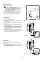
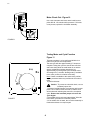
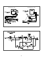
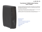
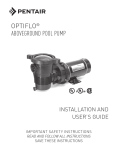
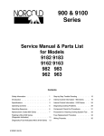
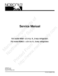
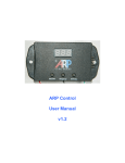
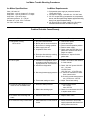
Ice Maker Trouble Shooting Procedures
Ice Maker Specifications
Ice Maker Requirements:
Volts: 120 volts AC
Amp Draw - cycle on, heater off: .03 amps
Amp Draw - cycle on, heater on: 1.6 amps
Amp Draw - cycle off: 0 amps
Inlet water pressure: 15 - 125 psi.
Duration of 1 cycle: 3.5 to 7 minutes
Ice Yield: 3 lbs./24 hours
1. Cold potable water supply at pressures between
15 psi and 125 psi.
2. 120 Volts AC supply - 108 VAC min -132 VAC max.
3. 1/4" O.D. cooper tubing (compression nut, compression
sleeve, and 90° degree tubing adapter supplied with refrig
erator) or an approved plastic tubing.
4. 1/4" Shut-off valve in water supply line. (Should be
accessible when the lower vent door is open.)
Problem/Probable Cause/Remedy
Problem
1. Refrigerator Cooling:
No ice in bin
Probable Cause
1.
2.
3.
4.
5.
A/C power disconnected.
Broken wire or loose connection.
Shut off arm in storage position.
Water supply shut off.
Inoperative water valve.
6. Excessive frost build-up causing
Shut-off arm to hang up.
2. Low ice yield.
1. Ventilation of refrigeration not in
accordance with Norcold’s Venting Requirements. See Section 2.
2. Insufficient refrigeration.
3. Not enough water supply pressure.
4. Thermostat setting too warm.
3. Excessive water dripping on ice
cubes or from Ice Maker mold.
1. Excessive water pressure.
2. Water valve sticking open.
Remedy
1.
2.
3.
4.
5.
Connect A/C power.
Locate and repair.
Place in normal operation position.
Restore water supply.
Check valve and inlet filter for restrictions or solenoid coil failure.
Repair or replace.
6. Defrost unit - inspect for door
gasket leak.
1. Install in accordance with Section
2 of this manual.
2. Check 120 VAC power 108 VAC
min. - 132 max.
12 VDC Power
10.5 VDC min. - 15.4 VDC max.
3. A. Check for restrictions in water
lines or water valve.
B. Check for correct water pressure.
min. 15 PSI; max. 125 PSI
4. Adjust Thermostat setting.
1. Correct water pressure
min. 15 PSI
max. 125 PSI
2. Check for contaminated inlet filter
or replace water valve.
4. Ice maker mold overfilling with
water.
1. Defective water valve.
1. Replace water valve.
5. Ice cubes are milky or have taste.
1. Water hardness or food stored in
ice bin.
1. Advise customer to have water
supply inspected and refrain from
storing food in the ice bin.
1
C503
Trouble Shooting Procedures
These check-out procedures are based on:
*
*
*
*
*
12 Volts DC (Control Voltage) is available to the Refrigerator.
120 Volts AC is available to the refrigerator and to the Ice Maker.
Water pressure to the Ice Maker is at 15 psi min. - 125 psi max.
Thermostat is set at mid-range setting or higher.
Refrigerator is performing satisfactory and has been operating
long enough to reach ice making temperatures.
* The Ice Maker’s shut-off arm in the down ON position.
Location of Test
Test points are located behind the white cover plate.
To gain acccess to the test point, the ice maker is
required to be moved from the freezer.
Test Points
5/16" Mounting Screws
Ice Maker Removal
1. Remove the ice bin and shelf.
2. Remove the two 5/16" mounting screws.
3. With a Phillips screwdriver, remove the 2 screws
under the Ice Maker.
4. Pull Ice Maker forward to remove.
5. Remove white cover plate.
6.Follow Check Out procedures.
White Cover Plate
Ice Bin
Shelf
FIGURE 1
Note: The wire harness is equipped with a thermal
fuse. The fuse protects the ice maker mold from
overheating. If the fuse is open, the wire harness
rerquires repplacement.
Wire Harness Check - Figure 6
The wire harness has a thermal fuse. The fuse
protects the ice maker mold from overheating. If the
fuse is open, the wire harness requires replacement.
Use a volt ohmmeter and check for 120 volts AC
between test points L and N.
Note: Insure your meter leads contact the surfaces
of the test points.
If 120 volts is present, proceed to "Water Valve" check
out.
If 120 volts is not present, replace the ice maker’s wiring harness.
FIGURE 2
2
C503
Water Valve Check
Energizing the Water Valve
Caution: To prevent an electrical shock, use an
insulated jumper wire.
Note: If water is available to the water valve,
performing the procedure below may overflow the ice maker’s mold.
Insert an insulated jumper wire between test points L &
V to energize the water valve. If an audible click or
buzzing is observed, the water valve is functional.
Ohm Readings
If the water valve is not functional:
FIGURE 3
1. Disconnect the refrigerator’s AC power cord from the
wall receptacle.
2. Use a volt ohmmeter; insert meter leads into test points
V & N.
3. Reading between 295 and 360 ohms indicate water
valve is functional.
4. Reading is infinity (maximum reading) there is a loose
wire connection at the water valve’s terminals or the
water valve is defective. Repair loose connection or
replace water valve.
5. Reading of "0" indicates a short in the wiring from the
ice maker to the water valve or a defective water valve
Repair the short or replace the water valve.
F1GURE 4
Mold Heater
Use a volt ohmmeter and insert meter leads into test
points L&H.
1. 75 ohm reading indicates the mold heater is functional.
2. Reading either an open or a short requires replacement
of the ice maker assembly.
F1GURE 5
3
C503
Motor Check-Out - Figure 10
Use a volt ohmmeter and insert meter leads into test
points M & N. 120 volts should be present. If 120 volts
is not present, replace the Ice Maker assembly.
FIGURE 6
Testing Motor and Cycle Function
Figure 11
This test procedure is to be performed while the ice
maker is dry and at room temperature.
The test cycle will take approximately 3-7 minutes to
complete. During the cycle the shut-off arm will raise
and lower slowly while the mold heater is on and the
ejector mechanism simulates ejecting the ice.
Approximately 3/4 through the cycle, the water valve
will energize for 7 seconds, allowing water (if available
to the valve) to fill the ice maker mold cavity.
Note: If water is available to the water valve, performing the procedure below may overflow the ice maker’s
mold.
To perform this test:
Caution: To prevent an electrical shock, use an
insulated jumper wire.
1. Insert an insulated jumper wire between and into test
points T & H. Within 15-20 seconds an audible click
will be observed indicating the start of the ice ejection
cycle. Remove the insulated jumper wire once the
cycle begins.
2.If an audible click is not heard, start with the "Wire Harness Check" procedure to locate the problem.
3. If an audible click is heard, the ice maker assembly is
functional and does not require repair.
FIGURE 7
4
Pictorial Before July 1, 1995
Pictorial Beginning July 1, 1995
Ice Maker Wiring Pictorial
5