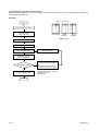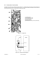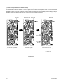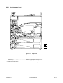
1
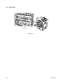
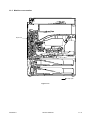
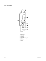
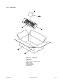
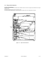
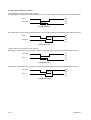
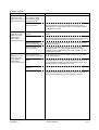
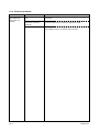
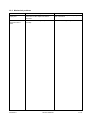
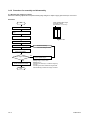
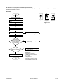
Option for copier
AD 63
SERVICE MANUAL
Code Y101570-4
CONTENTS
1-1 Specifications
1-1-1
1-1-2
1-1-3
1-1-4
Specifications .......................................................................................................................................
Part names ...........................................................................................................................................
Machine cross section ..........................................................................................................................
Drive system ........................................................................................................................................
1-1-1
1-1-2
1-1-3
1-1-4
1-2 Installation
1-2-1 Unpacking ............................................................................................................................................ 1-2-1
1-3 Troubleshooting
1-3-1 Paper misfeed detection ......................................................................................................................
(1) Paper misfeed indication ...............................................................................................................
(2) Paper misfeed detection conditions ..............................................................................................
(3) Paper misfeeds .............................................................................................................................
1-3-2 Electrical problems ...............................................................................................................................
(1) The duplex feed clutch does not operate. .....................................................................................
1-3-3 Mechanical problems ...........................................................................................................................
(1) Paper jams. ...................................................................................................................................
(2) Abnormal noise is heard. ..............................................................................................................
1-3-1
1-3-1
1-3-2
1-3-3
1-3-4
1-3-4
1-3-5
1-3-5
1-3-5
1-4 Assembly and Disassembly
1-4-1 Precautions for assembly and disassembly .........................................................................................
(1) Precautions ...................................................................................................................................
1-4-2 Procedure for assembly and disassembly ...........................................................................................
(1) Adjusting the margin for printing ...................................................................................................
(2) Adjusting the amount of slack at the registration roller .................................................................
(3) Adjusting the center line of image printing ....................................................................................
1-4-1
1-4-1
1-4-2
1-4-2
1-4-3
1-4-4
2-1 Mechanical construction
2-1-1 Construction of each section ................................................................................................................ 2-1-1
(1) Paper conveying operation in duplex copying .............................................................................. 2-1-2
2-2 Electrical Parts Layout
2-2-1 Electrical parts layout ........................................................................................................................... 2-2-1
2-3 Appendixes
Periodic maintenance procedures .................................................................................................................. 2-3-1
1-1-1
Y101570-4
1-1-1 Specifications
Type ............................................... Enclosed
Paper .............................................. Plain paper: 75 – 80 g/m2
Special paper: colored paper
Paper sizes .................................... A3 – A5R, folio/11" × 17" – 51/2" × 81/2"
Power source ................................. Electrically connected to the copier
Weight ............................................ Approximately 4.8 kg/10.56 lbs
Y101570-4
Service Manual
1-1-1
1-1-2 Part names
Duplex unit
Figure 1-1-1
1-1-2
Y101570-4
1-1-3 Machine cross section
Duplex unit
Paper path
Figure 1-1-2
Y101570-4
Service Manual
1-1-3
1-1-4 Drive system
Figure 1-1-3
1
2
3
4
5
6
7
1-1-4
Pulley T30
Duplex belt
Pulley T30
Duplex feed clutch gear
Gear 25
Idle gear 20
Gear 25
Y101570-4
1-2-1 Unpacking
Figure 1-2-1
1
2
3
4
5
6
7
Y101570-4
Unpacking
Duplex unit
Nut plate
M3 × 10 bronze binding screws
Outer case
Bar-code label
Air-padded bag
Plastic bag
Service Manual
1-2-1
1-3-1 Paper misfeed detection
(1) Paper misfeed indication
When paper jams, the machine immediately stops operation and the occurrence of a paper jam is indicated on the copier
operation panel.
To remove the jammed paper, open the conveying cover.
To reset the paper misfeed detection, open and close the conveying cover to turn safty switch 2 off and on.
FSSW
DUPPCSW
DUPFCL
FSW1
Figure 1-3-1 Paper misfeed detection
Y101570-4
Service Manual
1-3-1
(2) Paper misfeed detection condition
• Duplex paper conveying section 1 (jam code 60)
The duplex paper conveying switch (DUPPCSW) does not turn on within 1285 ms of the feedshift switch (FSSW) turning on.
FSSW
OFF
ON
DUPPCSW
OFF
1285 ms
ON
Timing chart 1-3-1
The duplex paper conveying switch (DUPPCSW) does not turn off within 1285 ms of the feedshift switch (FSSW) turning off.
FSSW
OFF
1285 ms
DUPPCSW
ON
OFF
ON
Timing chart 1-3-2
• Duplex paper conveying section 2 (jam code 61)
Feed switch 1 (FSW1) does not turn on within 1126 ms of the duplex paper conveying switch (DUPPCSW) turning on.
DUPPCSW
OFF
ON
FSW1
OFF
1126 ms
ON
Timing chart 1-3-3
Feed switch 1 (FSW1) does not turn off within 1126 ms of the duplex paper conveying switch (DUPPCSW) turning off.
DUPPCSW
OFF
1126 ms
FSW1
ON
OFF
ON
Timing chart 1-3-4
1-3-2
Y101570-4
(3) Paper misfeeds
Problem
(1)
Paper jams in the
duplex unit when the
main switch is turned
on.
Causes
A piece of paper torn from
copy paper is caught
around duplex paper
conveying switch.
Remove any found.
Defective duplex paper
conveying switch.
Run maintenance item U031 and turn the duplex paper
conveying switch on and off manually. Replace the switch if
indication of the corresponding switch on the operation panel is
not displayed in reverse.
(2)
Broken feedshift switch
Paper jams in the
actuator.
duplex unit during
Defective feedshift switch.
copying (jam in
duplex paper
conveying section 1).
Broken duplex paper
conveying switch actuator.
(3)
Paper jams in the
duplex unit during
copying (jam in
duplex paper
conveying section 2).
Y101570-4
Check procedures/corrective measures
Check visually and replace the feedshift switch if its actuator is
broken.
Run maintenance item U031 and turn the feedshift switch on and
off manually. Replace the switch if indication of the corresponding
switch on the operation panel is not displayed in reverse.
Check visually and replace the duplex paper conveying switch if
its actuator is broken.
Defective duplex paper
conveying switch.
Run maintenance item U031 and turn the duplex paper
conveying switch on and off manually. Replace the switch if
indication of the corresponding switch on the operation panel is
not displayed in reverse.
Broken duplex paper
conveying switch actuator.
Check visually and replace the duplex paper conveying switch if
its actuator is broken.
Defective duplex conveying
switch.
Run maintenance item U031 and turn the duplex paper
conveying switch on and off manually. Replace the duplex paper
conveying switch if indication of the corresponding switch on the
operation panel is not displayed in reverse.
Broken feed switch 1
actuator.
Check visually and replace feed switch 1 if its actuator is broken.
Defective feed switch 1.
Run maintenance item U031 and turn feed switch 1 on and off
manually. Replace the switch if indication of the corresponding
switch on the operation panel is not displayed in reverse.
Service Manual
1-3-3
1-3-2 Electrical problems
Problem
(1)
The duplex feed
clutch does not
operate.
1-3-4
Causes
Check procedures/corrective measures
Broken duplex feed clutch
coil.
Check for continuity across the coil. If none, replace the duplex
feed clutch.
Poor contact of the duplex
feed clutch connector
terminals.
Reinsert the connector. Also check for continuity within the
connector cable. If none, remedy or replace the cable.
Defective main PCB.
Run maintenance item U032 and check if CN10-B2 on the copier
main PCB goes low. If not, replace the main PCB.
Y101570-4
1-3-3 Mechanical problems
Problem
Causes/check procedures
Corrective measures
(1)
Paper jams.
Check if the duplex feed pulley, upper duplex
feed roller or lower duplex feed roller is
deformed.
Check visually and replace the pulley or
roller if deformed.
(2)
Abnormal noise is
heard.
Check if the rollers and gears operate
smoothly.
Grease the bushings and gears.
Y101570-4
Service Manual
1-3-5
1-4-1 Precautions for assembly and disassembly
(1) Precautions
• Be sure to turn the main switch off and disconnect the power plug before starting disassembly.
• When handling PCBs, do not touch connectors with bare hands or damage the board.
• Do not touch any PCB containing ICs with bare hands or any object prone to static charge.
• Use the following testers when measuring voltages:
Hioki 3200
Sanwa MD-180C
Sanwa YX-360TR
Beckman TECH300
Beckman DM45
Beckman 330*
Beckman 3030*
Beckman DM850*
Fluke 8060A*
Arlec DMM1050
Arlec YF1030C
* Capable of measuring RMS values.
• Prepare the following as test originals:
1. NTC (new test chart)
2. NPTC (newspaper test chart)
Y101570-4
Service Manual
1-4-1
1-4-2 Procedure for assembly and disassembly
(1) Adjusting the margin for printing
Perform the following adjustment if the printer leading edge margin for duplex copying (second face) is not correct.
Procedure
Printer leading edge margin
for duplex copying
(second face, 3 ± 2.5 mm)
Start
Enter maintenance mode.
Enter “402” using the numeric
keys.
Press the start key.
Figure 1-4-1
Select “TRAIL (DUP)”.
Press the start key.
Press the interrupt key.
The new setting is stored.
Press the start key to
output a test pattern.
No
Is the margin correct?
Yes
Press the stop/clear key
to exit maintenance mode.
End
1-4-2
Change the value using the
cursor up/down keys.
Setting range: –5.0 to +10.0
Reference: 4.5
Changing the value by 1 moves the margin by
0.5 mm.
Increasing the value makes the margin wider
and decreasing it makes the margin narrower.
Y101570-4
(2) Adjusting the amount of slack at the registration roller
Perform the following adjustment if the leading edge of the copy image is missing or varies randomly, or if the copy paper is
Z-folded during duplex copying.
Procedure
Start
Enter maintenance mode.
Original
Enter “051” using the numeric
keys.
Copy
example 1
Copy
example 2
Figure 1-4-2
Press the start key.
Select “RESIST DATA”.
Select “DUPLEX DATA”.
Press the interrupt key.
Press the start key.
The new setting is stored.
Make a test copy in duplex mode.
Is the leading
edge of the image missing
or varying randomly
(copy example 1)?
Yes
Increase the value using the
cursor up key.
Yes
Decrease the value using the
cursor down key.
No
Is the copy paper
Z-folded (copy example 2)?
No
Press the stop/clear key
to exit maintenance mode.
End
Y101570-4
Setting range: –30 to +20
Reference: 0
Changing the value by 1
changes the amount of slack
by 0.1 mm.
Initial setting: 0
The greater the value,
the larger the amount of slack;
the smaller the value,
the smaller the amount of slack
Service Manual
1-4-3
(3) Adjusting the center line of image printing
Make the following adjustment if there is a regular error between the center lines of the copy image and original when
copying using the duplex unit.
Procedure
Center line of printing
Start
Enter maintenance mode.
Enter “034” using
the numeric keys.
Correct image
Output
example 1
Output
example 2
Figure 1-4-3
Press the start key.
Select “LSU OUT (DUP)”.
Press the interrupt key.
Press the start key.
The new setting is stored.
Press the start key to
output a test pattern.
Is the image correct?
No
For output example 1, decrease
the value using the cursor down
key.
For output example 2, increase
the value using the cursor up key.
Yes
Press the stop/clear key
to exit maintenance mode.
Setting range: –5.0 to +5.0
Changing the value by 1 moves the
center line by 1.0 mm.
Initial setting: 0
End
1-4-4
Y101570-4
2-1-1 Construction of each section
The duplex unit consists of the components shown in Figure 2-1-1. In duplex mode, after copying on to the reverse face of
the paper, the paper is reversed in the switchback section and conveyed to the duplex unit. The paper is then conveyed to
the copier paper feed section by the upper and lower duplex feed rollers.
1
2
3
4
5
6
Feedshift guide
Upper duplex feed roller
Lower duplex feed roller
Duplex feed pulley
Duplex feed pulley
Duplex paper conveying switch (DUPPCSW)
Figure 2-1-1 Duplex unit
MPCB
DUPPCSW
CN10-B4
DUPFCL
CN10-B2
Figure 2-1-2 Duplex unit block diagram
Y101570-4
Service Manual
2-1-1
(1) Paper conveying operation in duplex copying
Paper of which copying onto the reverse side is complete is conveyed to the switchback section, the eject motor switches
from nomal rotation to reverse rotation to switch the eject roller to reverse rotation, and the paper conveying direction is
reversed. Paper that has been switched back is conveyed to the duplex unit via the eject roller and the switchback roller.
Paper that has been conveyed to the duplex unit is conveyed to the paper feed section again by rotation of the upper duplex
feed roller and the lower duplex feed roller and copying onto the front side is performed.
Eject roller
Switchback roller
Eject roller
Eject roller
Upper duplex
feed roller
Lower duplex
feed roller
Copying onto reverse side
(normal rotation of eject motor)
Switchback operation
(reverse rotation of eject motor)
Copying onto front side
(normal rotation of eject motor)
Paper path
Figure 2-1-3
2-1-2
Y101570-4
2-2-1 Electrical parts layout
1
2
;
Machine front
Machine inside
Machine rear
Figure 2-2-1 Duplex unit
1. Duplex paper conveying switch
(DUPPCSW) ................................................ Detects a paper jam in the duplex unit.
2. Duplex paper feed clutch
(DUPFCL) .................................................... Controls the drive of the duplex feed roller.
Y101570-4
Service Manual
2-2-1
Periodic maintenance procedures
Section
Paper
conveying
section
Y101570-4
Maintenance
part/location
Method
Maintenance cycle
Points and cautions
Upper duplex feed roller
Clean
Every service
Clean with alcohol or a dry cloth.
Lower duplex feed roller
Clean
Every service
Clean with alcohol or a dry cloth.
Service Manual
Page
2-3-1
UPD
ATING ST
ATUS
UPDA
STA
DATE
11/2001
UPDATED PAGES
1st EDITION
PAGES
25
CODE
Y101570-4