1
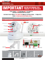
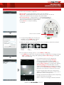
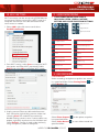
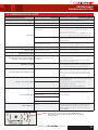
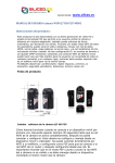
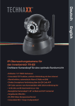
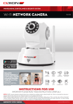
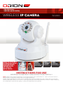
PROFESSIONAL
SURVEILLANCE SYSTEM
WIRELESS IP CAMERA
REMOTE CONTROL
OPERATION FROM
SMARTPHONES,
TABLETS& PCs
FULL PAN & TILT
MOTION CONTROL
MOTION
DETECT
120˚
MOTION SENSOR
TRIGGERS ALARM,
SENDS EMAIL ALERT AND
INITIATES RECORDING
SC200
INBUILT
MICROPHONE
& SPEAKER
FOR 2-WAY AUDIO
COMMUNICATION
NIGHT
VISION
10 INFRA-RED LEDs
FOR NIGHT VISION
OF UP TO 10m DISTANCE
355˚
INSTRUCTIONS FOR USE
IMPORTANT! PLEASE READ THESE INSTRUCTIONS CAREFULLY.
NOTE: SC200 IP camera requires network device (e.g. wireless/non-wireless router, network switch etc…) that is connected to internet or
internal network for setup and use. Network device is not supplied with this kit.
SC200 IP camera might experience network, motion command and live transmission DELAY issues. This is normal, due to the connected
network, 3G/4G mobile network, server overflow or internet upstream speed, download speed and video resolution. To improve delay issue,
it is recommended to reduce the video quality, or contact your mobile/network service provider.
PROFESSIONAL
SURVEILLANCE SYSTEM
IMPORTANT
BEFORE RETURNING THIS
PRODUCT TO THE RETAILER
PLEASE CONTACT
IF YOU HAVE ANY
CONCERNS OR PROBLEMS WITH THIS PRODUCT
Customer Service Phone: (03) 9982 5111 (Monday to Friday 8.30am – 5.30pm EST)
Email: [email protected]
For further information visit www.orionlive.com.au
1 IDENTIFICATION
ANTENNA
10 INFRA-RED LEDs
SCREW HOLE
SCRE
MOUNTING
FOR MO
BRACKET
BRAC
CAMERA LENS
& SENSOR
MICROPHONE
TILT/PAN
CAMERA HEAD
IP CAMERA LABEL
AUDIO OUTPUT
MOUNTING
BRACKET
CONTENTS:
LAN INPUT
IP CAMERA
MOUNTING
BRACKET
POWER SUPPLY
WIRELESS ANTENNA CONNECTION
MICRO
SD CARD
SOCKET
ETHERNET
CABLE
EXTERNAL
ALARM
CONNECTION
POWER SUPPLY
CONNECTION
MOUNTING SCREWS,
PLUGS
USER MANUAL
4 X DETERRENT
STICKERS
2
WIRELESS IP CAMERA SC200
PROFESSIONAL
SURVEILLANCE SYSTEM
2 FEATURES
› 2.4GHz wireless, range depends on location, tem-
perature and wireless network device
(e.g. wireless router)
› H.264 video compression
› IP camera mode records VGA or QVGA at 25FPS
(frames per second) VGA resolution 640x480,
QVGA resolution 320x240
› Micro SD card slot, support SDHC memory card
›
›
›
›
up to 32GB
Simultaneously view & record from IP cameras
Independent motion-detect recording
Built in microphone
CMOS colour cameras with 10 IR LED’s for up to
10 metres night vision
3 RESPONSIBLE USE
Please ensure this equipment is used in accordance with any local laws or regulations, especially if your
device is capable of audio recording. Users of this equipment should at all times act responsibly and consider
the reasonable expectations of privacy of individuals. Surveillance should be for a legitimate purpose related
to the activities of the person or organisation conducting it. We recommend that you clearly indicate (written
or otherwise) that surveillance is in operation in the monitored area.
4 WARNING
› Do not drop, puncture, or disassemble the camera.
› Do not tug the power supply or any connected cable, remove connection gently.
› Do not mount directly expose/near to the sun, rain, radio transmitting devices,
metal objects or heat sources.
› Do not crush or damage the power cable.
› Do not cover the unit, leave adequate space for ventilation and pan/tilt motion.
› Use the cameras with care, do not exert any force on the camera.
5 SYSTEM INSTALLATION
1.
2.
3.
4.
5.
6.
Do not permanently mount the IP camera during set up stage.
Install the antenna, network cable and power supply to IP camera.
Connect power supply to a 240V power point.
Wait for 1 minute while the IP camera undergoes a self diagnostic test.
Plug the other end of the network cable to a router or devices with network and internet connectivity.
Once the IP camera is set up correctly, fix the IP camera on the mounting bracket and mount it at
your desired location.
7. If the displayed image is blurry or poor, the camera is not focused. Rotate the white knob on the camera
lens to adjust focus.
WIRELESS IP CAMERA SC200
3
PROFESSIONAL
SURVEILLANCE SYSTEM
6 APPLE DEVICES (IPHONE/IPAD)
INSTALL IP CAMERA > INSTALL APP > REGISTER AN ACCOUNT > ADD IP
CAMERA TO THE ACCOUNT > READY TO USE
1. Complete system installation according to Section 5.
IMPORTANT: DHCP service must be enabled on the network device.
* For first use, it is recommended that the Apple device is connected via Wi-Fi and
IP camera is connected via network cable to the same local area network.
2. Before installation, ensure your Apple device has 3G/4G or WI-FI internet
connectivity. Go to Apple app store, search, download and install Plug2view.
3. After successfully installed, Plug2View app logo will be available on your Apple
device screen.
4. Open the Plug2View app.
5. Register account by pressing Register, fill in the information and then select OK
to complete.
6. Go back to the main page of the Plug2View app, login using the user name and
password previously registered.
7. After successful login, there are two network sections, Remote (for remote
connection) and Local (local area network connection).
8. If the Apple device and IP camera is connected as LAN connection, cameras
within the LAN will show up automatically, no configuration or registering
required. IP cameras connected will be listed on the local device list under Local
section, select the IP camera to view. If the IP camera does not show up on the
Local list page, tap the Refresh button on the top right to refresh
the page.
9. Remote connection allows the camera to be viewed from a remote network. For
Remote option, press the Option key located at the top-right hand corner and
select Add Device to add the IP camera.
4
WIRELESS IP CAMERA SC200
PROFESSIONAL
SURVEILLANCE SYSTEM
10. Fill in the information required:
• Device Alias – (optional) Assign a name to the IP camera.
• Device ID – (required) Refer to label at the bottom of the IP camera and
enter Device ID. (Device ID must be exact match).
• Access Password – (required) Refer to label
at the bottom of the IP camera and enter
Access password. (Access Password must
be exact match).
• Select Done to complete adding IP camera.
DEVICE ID AND PASSWORD
11. If successfully added, the IP camera is available on the Remote list page.
Simply select the IP camera for viewing.
12. When IP camera is connected, Pan/Tilt, Photo Snapshot, Video Record and
Audio Listen functions are enabled:
Pan/Tilt
Motion
Control
Photo
Snapshot
Video Record
Audio Listen
13. For IP camera settings, press > on the local /remote device list page:
• For Remote connection the IP camera only able to adjust the following settings:
Video settings for setting video quality and SD card settings for SD card video
record setting.
• For Local connection the IP camera can
adjust the following settings: Wired
setting for configuring network settings,
Wireless setting for setting up WIFI
connection with wireless router,
Video setting for setting video quality
and SD card setting for SD card video
record setting.
* If experiencing video distortions and control
delays, reduce camera resolution, frame rate
or data rate in video settings menu.
* Change password immediately after
completing setup to protect your privacy.
Refer to Section 15 Change Camera
Password.
WIRELESS IP CAMERA SC200
5
PROFESSIONAL
SURVEILLANCE SYSTEM
7 ANDROID DEVICES
INSTALL IP CAMERA > INSTALL APP > REGISTER AN ACCOUNT > ADD IP
CAMERA TO THE ACCOUNT > READY TO USE
1. Complete system installation according to Section 5.
IMPORTANT: DHCP service must be enabled on the network device.
* For first use, it is recommended that the Android device is connected via Wi-Fi
and IP camera is connected via network cable to the same local area network.
2. Before installation, ensure your android device has 3G/4G or WI-FI
internet connectivity. Go to Google play store search, download and install
p2pCamViewer.
3. After successfully installed, Plug&Play app logo will be available on your
android device screen.
4. Open the Plug&Play app.
5. Register account by pressing Register, fill in the information and then select OK
to complete.
6. Go back to the main page of the Plug&Play app, login using the user name and
password previously registered.
7. After successful login, there are two network sections, WAN (for remote
connection) and LAN (local area network connection).
8. If the android device and IP camera is connected as LAN connection, cameras
within the LAN will show up automatically, no configuration or registering
required. IP cameras connected will be listed on the device list under LAN
section, select the IP camera to view. If the IP camera does not show up on the
LAN page, tap Button to Refresh the page.
9. For WAN option, press the + key located at the top-right hand corner to add
the IP camera.
6
WIRELESS IP CAMERA SC200
PROFESSIONAL
SURVEILLANCE SYSTEM
10. Fill in the information required:
• Device Alias– (optional) Assign a name to the IP camera.
• Device ID – (required) Refer to label at the bottom of the IP camera
and enter Device ID. (Device ID must be exact match).
• Access Password – (required) Refer to label at the bottom of
the IP camera and enter Access Password.
(Access Password must be exact match).
• Select Done to complete adding
IP camera.
DEVICE ID AND PASSWORD
11. If successfully added, the IP camera is
available on the WAN page. Simply
select the IP camera for viewing.
12. When IP camera is connected, Pan/Tilt, Photo Snapshot, Video Record and
Audio Listen functions are enabled:
Pan/Tilt
Motion
Control
Photo
Snapshot
Video Record
Audio Listen
14. For IP camera settings, press > on the WAN or LAN page
• For WAN connection the IP camera only able to adjust the following settings:
Video settings for setting video quality and SD card settings for SD card
video record setting.
• For LAN connection the IP camera can
adjust the following settings: Ethernet
for configuring network settings, Wi-Fi
for setting up WIFI connection with wireless
router, Video settings for setting video quality,
SD card settings for SD card video record
setting, SD card query for searching recorded
video on SD card and Alarm setting for setting
camera motion detection and user alert email.
* If experiencing video distortions and control
delays, reduce camera resolution, frame rate or
data rate in video settings menu.
* Change password immediately after completing
setup to protect your privacy.
Refer to Section 15 Change Camera Password.
WIRELESS IP CAMERA SC200
7
PROFESSIONAL
SURVEILLANCE SYSTEM
8 DESKTOP/NOTEBOOK COMPUTER
INSTALL IP CAMERA > INSTALL SOFTWARE CD >
REGISTER AN ACCOUNT > ADD IP CAMERA TO THE
ACCOUNT > READY TO USE
1. Complete system installation according to Section 5.
IMPORTANT: DHCP service must be enabled in the
network device.
* For first use, it is recommended that the desktop/
notebook is connected via network cable/Wi-Fi and IP
camera is connected via network cable to the same local
area network.
2. Insert CD into your computer, install the software
SYSM Monitor.exe or download software from
www.orionlive.com.au
3. First register an account by selecting Register located
at top-right corner, fill in the information, and then
click Register to complete.
4. After registering an account, go to Login located next
to register, login using the user name and password
previously registered.
5. After successful login, there are two network sections,
WAN (for remote connection) and LAN (local area
network connection).
6. If the computer and IP camera is connected as LAN
connection, cameras within the LAN will show up
automatically, no configuration or registering required.
IP cameras connected will be listed on the device list
under LAN section. Double click the IP camera to view.
If the IP camera does not show up on LAN, point the
mouse on the device list, right click and then click
Refresh to refresh the page.
7. WAN allows the camera to be viewed from a remote
network. For WAN option, click on WAN, then right
click on the blank WAN list, go to Add device to add
the IP camera.
8. Fill in the information required:
• Device Alias – (optional) Assign a name to
the IP camera.
• Device ID – (required) Refer to label at the bottom of
the IP camera and enter Device ID. (Device ID must
be exact match).
• Device Access Password – (required) Refer to label
at the bottom of the IP camera and enter Access
Password. (Access Password must be exact match).
• Click Done to complete adding IP camera.
8
WIRELESS IP CAMERA SC200
PROFESSIONAL
SURVEILLANCE SYSTEM
9. If successfully added, the IP camera is available on the
WAN list page. Simply double click on the IP camera
for viewing.
10. When IP camera is connected, Pan/Tilt, Photo Snapshot,
Video Record and Audio Listen functions are enabled:
Pan/tilt
motion control
Photo
Snapshot
Video Record
Audio Listen
* To view recorded files, click
settings, located near
the top-left hand corner, click Monitor tab and then
double click on source address to go into recorded
files. Recorded files directory on PC can be changed in
this setting window.
11. For IP camera settings, point the mouse on to the
connected IP camera on the WAN/LAN page and
right click on the mouse:
• For WAN connection the IP camera only able
to adjust the following settings: Change watch
password for change the IP camera access
password on the IP camera label, Change the
device alias for changing the device given name
and SD card query for searching recorded video
on SD card.
• For LAN connection the IP camera can adjust the
following settings: Change watch password for
change the IP camera access password on the IP
camera label, Change the device alias for changing
the device given name, Set Wi-Fi connection for
setting up Wi-Fi connection with wireless router
(press SCAN to search for Wi-Fi connection), SD
card configuration for SD card video record setting
and SD file download for searching recorded video
on SD card.
Configure video quality settings by selecting camera video
and select camera setting button
.
* If experiencing video distortions and control delays,
reduce camera resolution, frame rate or data rate in video
settings menu.
* Change password immediately after completing setup to
protect your privacy.
Refer to Section 15 Change Camera Password.
WIRELESS IP CAMERA SC200
9
PROFESSIONAL
SURVEILLANCE SYSTEM
9 NETWORK SETTING
Camera is connected to network using DHCP
protocol in default settings. Using DHCP, the
camera automatically obtains the IP address from
the networking device (router/modem). Make sure
DHCP is enabled on your networking device (router/
modem).
To access network settings, right-click camera in
LAN device list and select Set the IP address.
Configuring network settings requires camera and
control device (Apple/Android/Computer) to be
connected to the same local network by connecting
them to the same networking device (router/
modem). The camera will appear in the Local/LAN
device list.
If camera does not appear on LAN, it might
be due to:
• IP camera and network device are not connected
properly. Check all the cable connections and
make sure they are all connected securely. Note
that the camera takes a few minutes to perform
self diagnostic test after it is turned on. After this
test, right-click LAN box and select Refresh to
update LAN device list.
• Your network has 2 or more DHCP servers.
Commonly, most networks have only one DHCP
server. Make sure that the camera is connected to
a network with only one DHCP server. In a network
with 1 DHCP server, the camera automatically
obtains IP address and the software can
automatically detect camera.
10
• DHCP: It is recommended to use DHCP (Dynamic
Host Configuration Protocol) for camera to
automatically obtain IP address from DHCP
enabled networking device (router/modem).
• Fixed IP: Select Fixed IP to manually enter
network settings. Enter the IP address, Subnet
mask, Gateway address and Preferred DNS server.
• Mac address: This is a unique identifier for the
camera.
• Only use the device in LAN: Checking this will
disable camera from being able to be viewed from
a remote network.
• Device Status: Displays current camera
connection status.
WIRELESS IP CAMERA SC200
PROFESSIONAL
SURVEILLANCE SYSTEM
10 WI-FI SETTING
11 VIDEO MONITORING
Wi-Fi connection can be set up using SYSM Monitor
on computer. Before commencing Wi-Fi setup, the
computer and camera must be connected to the
same router or modem.
›
VIDEO MONITORING FUNCTION IS
INCLUDED LISTEN, VIDEO, CAPTURE,
SETTING AND CLOSE FUNCTION BUTTONS:
Optical Zoom
1. Select LAN, right-click camera and select
Set WIFI connection.
Digital Zoom
Aperture Switch
2. Start Wi-Fi setting, select Scan to search for Wi-Fi
connection and enter Wi-Fi password. Enable
DHCP and select OK to complete Wi-Fi setup.
Capture Photo
Set to Preset Position
Record Video
Set Pan/Tilt Speed
Listen
Vertical Flip
Talk
Mirror
Motion Detect
Cruise
Horizontal Pan
Alarm Log
Vertical Tilt
Setting
Go to Preset Position
12 RECORD MODE
› Record Folder
Video recordings and photo snapshots are stored
and
in a specified folder. Select Setting button
select Monitor tab.
3. Unplug camera Ethernet cable and disconnect
from camera by right-clicking camera video and
selecting Close. Re-establish connection by
double-clicking camera name. If camera does not
appear, right-click anywhere on the LAN box and
select Refresh. Camera is ready to be wirelessly
using smartphone, tablet or computer.
› Manual Record
Select Photo Capture
into specified folder.
Select Video Record
specified folder.
WIRELESS IP CAMERA SC200
to take photo snapshot
to start video record into
11
PROFESSIONAL
SURVEILLANCE SYSTEM
› Schedule Record
› Motion Detect Record
1. Right-click camera in LAN and select Set Local
Video Plan.
2. Select the day of the week and select Add to
add period when camera commences video
recording. Select 24*7 to enable continuous
recording.
1. Select Setting button
Plan tab.
and select Local Alarm
• Select Local alarm record to enable video record
onto local PC when alarm is triggered. Enter the
length of the video recording.
• Select Local alarm capture to enable photo
snapshot onto local PC when alarm is triggered.
Enter the delay between alarm trigger and photo
snapshot.
• Select Local alarm music to enable sound
notification when alarm is triggered. Select
sound file.
2. Select OK to complete setup.
3. Select Motion Detect
on bottom toolbar.
3. Select Apply to complete schedule recording
setup.
4. Alarm sensitivity determines the amount of
movement that triggers motion alarm. Select
suitable alarm sensitivity. Select New Detection
Area to determine the area of the video that
detects movement.
12
WIRELESS IP CAMERA SC200
PROFESSIONAL
SURVEILLANCE SYSTEM
5. Select Apply to complete motion alarm setup.
6. Camera is ready to detect movement in the
video and commence video recording. Note that
controlling the camera pan/tilt motion will trigger
motion detect alarm as it detects movement in
the video.
Check the recording options to enable recording.
Select Format SD Card to clear all files from card.
13 VIDEO PLAYBACK
6. Select Apply to complete setting.
› Viewing SD card Recordings
1. Select
Playback button on top toolbar to
open Playback menu.
2. Select Playback to search for recordings. Search
for specific recording by selecting start time and
end time.
3. Double-click any file to play recording.
14 SD CARD
Video can be recorded directly onto a micro SD
card which is installed on the camera to record
video without the use of computer, tablet or PC.
Camera supports micro SD card with storage
capacity of up to 32GB.
1. Open the SYSM
Monitor software,
right-click on camera
in LAN/WAN and
select SD File
Download.
2. Select Search to
display all the
recorded files on the
SD card. Double-click
any file to download
onto local PC. Select
Open download directory to view downloaded
files.
› Configuring SD Card
1. Obtain a micro SD card
and remove all files by
formatting the card on
a computer.
2. Insert the card into the
slot on the rear panel
of camera.
3. Restart the camera by
turning off and on the
power supply.
4. Open the SYSM
Monitor software, right-click on camera in LAN
and select SD Card Configuration.
5. Check whether the camera detects micro SD card
by checking storage capacity.
WIRELESS IP CAMERA SC200
13
PROFESSIONAL
SURVEILLANCE SYSTEM
15 CHANGE CAMERA PASSWORD
1. Open SYSM Monitor and login to account.
2. Select Device Management .
16 SPECIFICATIONS
› VIDEO
Sensor
Image Resolution
Lens
Min Illumination
6mm Colour CMOS Sensor
640 x 480 pixels (0.3 Megapixels)
F: 3.6mm
0.5 Lux
Compression Format
H.264
Frame Rate
25 fps
Display Resolution
640 x 480 (VGA)
320 x 240 (QVGA)
› AUDIO
Compression Format
Input
Output
ADPCM
Built-in microphone
Built-in speaker or external
› NIGHT VISION
Infrared Light
10 IR LEDs
Range
Up to 10m
› ALARM
Detection Method
Alarm Action
Motion Detection, Wired Input
Record Trigger, Wired Output, FTP
Upload, Message to Server
› PAN & TILT
Pan/Tilt/Speed
3. Select a device from
the list and select
Change Management
Password.
4. Enter the new
password and verify it
by entering it again.
5. Select OK to confirm
changing password.
6. This new password will be required when adding
camera.
355°/120°/15-70°/s
› NETWORK
Ethernet
Supported Protocol
Wireless Standard
Wireless Security
10/100Mbps RJ-45
TCP/IP, HTTP, TCP, ICMP, UDP, ARP,
IGMP, SMTP, FTP, DHCP, DNS, DDNS,
NTP, UPnP, RTSP, PPPoEs
IEEE 802.11b/g
WEP/WPA/WPA2 Encryption
› GENERAL
Power Supply
DC 5V 2A
Data Storage
Micro SD Card (32GB Max)
Dimensions
110(L) x 100(W) x 108(H)mm
17 WARRANTY
Arlec guarantees this product in accordance with the Australian
Consumer Law.
Arlec also warrants to the original first purchaser of this product
(“you”) from a retailer that this product will be free of defects
in materials and workmanship for a period of 12 months from
the date of purchase; provided the product is not used other
than for the purpose, or in a manner not within the scope of the
recommendations and limitations, specified by Arlec, is new and
not damaged at the time of purchase, has not been subjected
to abuse, misuse, neglect or damage, has not been modified or
repaired without the approval of Arlec and has not been used for
commercial purposes (“Warranty”).
If you wish to claim on the Warranty, you must, at your own expense,
return the product, and provide proof of original purchase and your
name, address and telephone number, to Arlec at the address
below or the retailer from whom you originally purchased the
product within 12 months from the date of purchase.
14
Arlec will (or authorise the retailer to) assess any claim you may make
on the Warranty in the above manner and if, in Arlec’s reasonable
opinion, the Warranty applies, Arlec will at its own option and
expense (or authorise the retailer to) replace the product with the
same or similar product or repair the product and return it to you
or refund the price you paid for the product. Arlec will bear its
own expenses of doing those things, and you must bear any other
expenses of claiming on the Warranty.
The Warranty is in addition to other rights and remedies you
may have under a law in relation to the product to which the
Warranty relates.
Our goods come with guarantees that cannot be excluded under
the Australian Consumer Law. You are entitled to a replacement or
refund for a major failure and for compensation for any other
reasonably foreseeable loss or damage. You are also entitled to
have the goods repaired or replaced if the goods fail to be of
acceptable quality and the failure does not amount to a major failure.
WIRELESS IP CAMERA SC200
PROFESSIONAL
SURVEILLANCE SYSTEM
18 TROUBLESHOOTING GUIDE
PROBLEM POSSIBLE CAUSE
IP Camera has no power or not powering up
SD card is not detected by IP camera
SUGGESTED REMEDY
Power supply is loose or unplugged.
No power at socket outlet/power point.
Check all cable and power supply connections.
SD card not formatted
Format SD card, please see “Section 14”.
IP Camera out of range
Relocate IP camera closer to wireless router.
IP Camera not connected to
LAN or Wi-Fi
Check all cable and power supply connections.
Check power at socket outlet/power point.
Check network device (e.g. wireless/non-wireless
router, network switch etc...).
Restart the IP camera Click or tap “REFRESH” on the
control device (Apple/Android/Desktop/Notebook).
No picture
Signal interference
Relocate IP camera away from sun, rain, radio
transmitting devices, heat sources, metal objects or
major obstacles.
No power at IP camera or no power at
socket outlet/power point
Check all cable and power supply connections.
Frozen white screen
Check power at socket outlet/power point.
Disconnect power to IP camera and then reconnect.
When IR night vision is activated, screen only
displays white
Infra-red LED light is reflected off from
glass or reflective objects
Relocate IP camera away from windows, reflective and
glass objects or remove obstacles.
When IR night vision is activated, screen only
displays black and white
Infra-red LED light is activated
This is normal. No action required.
IP Camera is not set up correctly.
SD memory card missing or not
compatible
Check IP Camera date and time, schedule setting and
motion detect setting.
IP Camera does not record according to
schedule or motion detect settings
Save necessary files on control device (Apple/Android/
Desktop/Notebook) then format current SD memory
card or insert new SD memory card and format.
SD memory card full
Mute is on
Turn off mute.
Note: Audio recording is prohibited or illegal in
some states, or required consent from both parties.
Please consult your local legal advisers before audio
recording.
Recorded videos does not have sound
Blurry or poor image quality
Check SD memory card is inserted in the IP Camera
properly and compatible to use.
Signal interference
Relocate camera and IP Camera away from sun, rain,
radio transmitting devices, heat sources, metal objects
or major obstacles.
Camera lens not focused
Relocate IP camera closer to wireless router.
Check antenna connection.
Manually adjust camera lens to adjust focus.
Low or unstable signal
Antenna
Adjust antenna connection or relocate IP camera closer
to wireless router.
Signal interference
Relocate IP camera away from sun, rain, radio
transmitting devices, heat sources, metal objects or
major obstacles.
Strong radio emitting or transmitting
devices nearby
Strong electromagnetic interference
nearby
Too close to metal objects
Audio interference
IP Camera are too close to other vocal
devices
IP Camera has a high sensitivity microphone.
Keep the IP camera and other vocal devices at least
5 metres apart. If the IP camera must be within 5
metres of other vocal device, reduce the volume or
turn on MUTE.
* If password is lost, use a tool to press RESET button
under the IP camera. It will reset the IP camera to default
factory setting.
WIRELESS IP CAMERA SC200
15
PROFESSIONAL
SURVEILLANCE SYSTEM
Arlec Australia Pty. Ltd. ACN 009 322 105 (“Arlec”) gives the Warranty.
Arlec’s telephone number, address and email address are:
Customer Service: (03) 9982 5111
New Zealand Toll Free: 0800 003 329
Building 3, 31 – 41 Joseph Street, Blackburn North, Victoria, 3130
Blackburn North LPO, P.O. Box 1065, Blackburn North, 3130
Email: [email protected]
CPIN002642/2