1
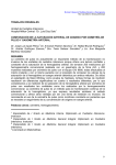
MODELS I2C and I2CI/2C95 TWO-STAGE CENTRIFUGAL PUMPS INSTALLATION AND SERVICE MANUAL NOTE! To the installer: Please make sure you provide this manual to the owner of the equipment or to the responsible party who maintains the system. Part # 13800A429 | © 2015 Pentair Ltd. | 10/23/15 Warning! Important safety instructions! Read carefully before installation. Never operate a pump with a frayed or brittle power cord and always protect it from sharp objects, hot surfaces, oil and chemicals. Avoid kinking the cord. California Proposition 65 Warning: Never service a motor or power cord with wet hands or while standing in or near water or damp ground. This product and related accessories contain chemicals known to the State of California to cause cancer, birth defects or other reproductive harm. The three phase units must be wired by a qualified electrician, using an approved starter box and switching device. Safe Drinking Water Act: This product is to be used exclusively for non-potable water services. This product is not anticipated to be used for human consumption so is not designed for the low lead levels stated in the Safe Drinking Water Act. It is illegal to use this product for potable water applications for human consumption, such as drinking water, oral hygiene, hand washing, food preparation and dishwashing. Do not use this pump in or near a swimming pool. Single phase motors are equipped with automatic resetting thermal protectors. The motor may restart unexpectedly, causing the leads to energize or pump to turn on. Three phase motors should be protected by proper, thermal and amperage protection. (Check local codes.) Failure to follow these instructions and comply with all codes may cause serious bodily injury and/or property damage. Check for nicks in the wire and pump insulation by using an ohmmeter and checking resistance to ground before installing the pump and after installing the pump. If in doubt on the proper procedure, check with a qualified electrician. Before installing or servicing your pump, be certain the pump power source is turned off and disconnected. All installation and electrical wiring must adhere to state and local codes. Check with appropriate community agencies or contact your local electrical and pump professionals for help. Do not pump gasoline, chemicals, corrosives or flammable liquids; they could ignite, explode or damage the pump, causing injury and voiding the warranty. Do not run this pump with discharge completely closed. This will create superheated water, which could damage the seal and shorten the life of the motor. This superheated water could also cause severe burns. Always use a pressure relief valve, set below the rating of the tank system. Call an electrician when in doubt. Pump must be connected to a separate electrical circuit directly from the entrance box. There must be an appropriately sized fuse or circuit breaker in this line. Tying into existing circuits may cause circuit overloading, blown fuses, tripped circuit breakers or a burned-up motor. Do not run the pump dry, fail to protect the pump from below freezing temperatures. Do not connect pump to a power supply until the pump is grounded. For maximum safety, a ground fault interrupter should be used. Caution: Failure to ground this unit properly may result in severe electrical shock. Never work on the pump or system without relieving the internal pressure. Do not pump water above 120° F. Warning: Reduced risk of electric shock during operation of this pump requires the provision of acceptable grounding. If the means of connection to the supply-connection box is other than grounded metal conduit, ground the pump back to the service by connecting a copper conductor, at least the size of the circuit conductors supplying the pump, to the grounding screw provided within the wiring compartment. Never exceed the pressure rating of any system component. GENERAL INSTALLATION The pump should be installed in a clean, dry and well ventilated place, allowing room to inspect and service pump and driver. This pump is provided with a means for grounding. To reduce the risk of electric shock from contact with adjacent metal parts, bond supply box to the pump-motor-grounding means and to all metal parts accessible including metal discharge pipes and the like, by means of a clamp, a weld or both if necessary, secured to the equipment-grounding terminal. The pump should be bolted securely to a solid foundation. The 2" NPT suction can be rotated at 90° intervals to four different positions. As standard, the suction will be on the right side when facing the pump end. The 1-1/2" NPT discharge can be rotated at 45° intervals to 8 different positions. As standard, the discharge will point up. Direct connected pumps should always be mounted in a horizontal position on a level foundation. The voltage and phase of the power supply must match the voltage and phase of the pump. Do not use an extension cord. Above ground joints must be made in an approved junction box. Direct connected units are accurately aligned at the factory, but all baseplates are flexible. A flexible coupling is intended to take care of only slight misalignment, therefore the pump and driver must be Do not work on this pump or switch while the power is on. 2 carefully aligned at the installation. Parallel alignment can be checked by placing a straight edge across the coupling halves. It must rest evenly on both halves at four positions spaced at approximately 90° intervals around the coupling. On belt driven units the pump and driver shafts should be parallel; the pulleys or sheaves must be aligned also. The pulley or sheave on both pump and driver should be mounted as close to the bearing housing as possible to minimize the overhang, allowing sufficient clearance for rotor and play. the pump to run for long periods with the discharge valve tightly closed as the liquid in the pump will get extremely hot. Before stopping the pump, close the discharge valve. This will prevent water hammer and is especially important on high head pumps. A properly installed check valve will perform the same function. Mechanical Seal Lubrication The pump is provided with an oil chamber which lubricates the seal face of the mechanical seal. The oil level should be checked every 50 hours. Belt Drives Avoid a vertical drive on flat belt drives; an angle of 45° or less between the line of shaft centers and the horizontal is desirable. The distance between the shaft centers should be at least twice the diameter of the larger pulley. Adjust belt tension just tight enough to prevent slippage. Bearings – Lubrication Pump bearings are sealed on one side and open on one side and are lubricated by grease in the bearing bracket. Normally, these bearings require no further attention. This grease cavity must not be overloaded and should not be filled more than about half full. Suction Piping Suction pipe should be direct and as short as possible. It should be at least one size larger than suction inlet tapping. It should have minimal elbows and fittings. Piping should slope upward to pump without dips or high points so that air pockets are eliminated. The highest point in the suction piping should be the pump inlet except where liquid flows to the pump inlet under pressure. To prevent air from being drawn into suction pipe due to a suction whirlpool, the foot valve should be submerged at least three feet below the low water level. Freezing Care should be taken to prevent the pump from freezing during cold weather. It may be necessary to drain the pump when not in operation. All individual chambers must be drained. To drain the suction chamber, remove the pipe plug that is in the bottom position. To drain the first and second stage impeller chambers, remove the two pipe plugs which are in the lower position of the case and the pipe plug in the crossover casting. Discharge Piping Discharge piping should never be smaller than pump tapping, rather one size larger. A gate valve should always be installed in discharge line to serve as a shutoff or throttling valve if capacity is not correct. To protect the pump and foot valve from water hammer, a check valve should be installed in the discharge line between the pump and gate valve. To Remove And Replace Worn Impeller and Wearing Rings To service pump, the suction and discharge piping must first be disconnected. Remove back plate. Remove impeller cap screw and washer in outer impeller eye. Remove tap bolts that hold volute case to bracket. Pry evenly and carefully to get volute case and outer impeller off. Electrical Connections All motors, unless provided with built-in overload protection, must be protected with an overload switch, either manual or magnetic. This switch is to be supplied by the customer. When the motor is mounted on a baseplate or on slide rails for adjustment, flexible metallic conduit should be used to protect the motor leads. Remove inner impeller and snap ring. Slide old seal off shaft and remove tap bolts holding bracket to bearing bracket and pull bracket off shaft. Remove old floating seat and seat cup from bracket. Make sure the synthetic seat cup of the new seal is tight against the shoulder of the floating seat, with rounded edge at the rear to facilitate insertion. Wipe the lapped sealing face of the floating seat and oil face with a clean, light oil. Priming The pump must be primed before starting. Be sure the pump case is filled with water so the mechanical shaft seal never runs dry. Remove the top pipe plugs while priming to assure that all air is evacuated. The individual chambers of the pump and the suction piping must be completely filled before starting motor. Oil the outer surface of the seat cup, using light oil, and push the assembly in the cavity of the bracket, seating it firmly and squarely. Replace lip seal and lubricate oil seal face. Clean and oil the surface of the shaft with a light oil. Bolt bracket back onto bearing bracket. Wipe the face of the sealing washer and oil with clean light oil. Put the sealing washer and bellows assembly on the shaft. The notches on the washer should mate with the lugs on the retainer. Press on assembly until it is tight against the floating seal. Rotation The pump must run in the direction of the arrow on pump case. Three phase motors may run either direction so if rotation is wrong when starting motor, interchange any two line leads to change rotation. Starting Close the discharge valve when starting the pump as it puts less starting load on the motor. When the pump is up to operating speed, open the discharge valve to obtain desired capacity or pressure. Do not allow Slip shaft seal spring over the shaft, making sure it and the spring holding plate are seated properly. Slip 3 snap ring over shaft and slide it forward until it drops into place. Install inner impeller, with suction opening toward bearing bracket, making sure that key is in place on shaft. Air leak in suction line. Check line under pressure to find leak. Place volute case back on and bolt it onto the bracket. Install outer impeller with suction opening away from bearing bracket. Assemble the impeller cap screw with a 3/8" helical spring lock washer. Tighten the cap screw. Impeller or suction line plugged. REPLACING WEAR RINGS Impeller diameter too small for condition required. With impellers removed, the wearing rings can be examined for wear and replaced if diameter clearance is over .030". Not enough pressure. Excessive volume being discharged. Throttle discharge valve. Cut worn rings from casing in half on opposite sides to be bumped out easily. Speed too low. Check pump drive belts for slippage. If hot, tighten belts. Check motor voltage and speed. Put new rings in place and bump in. New impeller wear rings should always be installed in a pump at the same time a new impeller is installed. Air leak in suction line. Check line under pressure to find leak. Insufficient submergence of suction pipe. Foot valve should be three feet below water level. Impeller and wearing rings badly worn. Disassemble pump and replace impeller and wearing rings if clearance on diameter is over .030" Rotation wrong. Change shaft rotation. Sediment chamber clogged. Remove and clean thoroughly. Make sure gasket is in good condition and sealing surfaces clean before reassembly of sediment chamber cap. REPLACE BEARINGS Pump end must be removed. Pry pulley and bearing retaining ring out and press shaft and bearings through pulley end of bearing bracket. Press bearings off shaft. Impeller or suction line plugged. Impeller and wearing rings badly worn. Disassemble pump and replace impeller and wearing rings if clearance on diameter is over .030". Reassemble by pressing new bearings on shaft, only on inner face of bearings. Insert shaft into housing. Seals on bearings must face out on installation with open sides facing in. Replace snap rings. Beveled snap ring goes on pump end bearing, with bevel facing pump end. Impeller diameter too small for condition required. Pump runs for a short while, then loses prime. Suction lift too high. Check with vacuum gauge. This should not exceed 15 feet. When pumping hot water, check NPSH. TROUBLESHOOTING No water delivered. Pump not properly primed; repeat priming operation. Air leak in suction line. Check line under pressure to find leak. Discharge head too high. Check total head with gauge at pump inlet and discharge (with water, the gauge would show shut-off pressure). Air pocket in suction line. Check line for proper slope. Insufficient submergence of suction pipe. Foot valve should be three feet below water level. Rotation wrong. Change shaft rotation. Suction strainer plugged. Clean strainer. Suction lift too high. Check with vacuum gauge. This should not exceed 15 feet. When pumping hot water recheck NPSH. Seal leaking. Seal is worn or seal face cocked. Replace with new seal and carefully follow directions. Air leak in suction line. Check line under pressure to find leak. Air pocket in suction line. Check line for proper slope. Impeller or suction line plugged. Not enough water delivered. Discharge head too high. Check total head with gauge at pump inlet and discharge (with water, the gauge would show shut-off pressure). Speed too low. Check pump drive belts for slippage. If hot, tighten belts. Check motor voltage and speed. Rotation wrong. Change shaft rotation. Suction lift too high. Check with vacuum gauge. This should not exceed 15 feet. When pumping hot water, recheck NPSH. 4 7 10 3 19 9 11 15 2 30 20 23 18, 29 23 4 23 10 16, 17, 29 12 25 26 8 1 27 5, 6 28, 29 23 29, 18 21 I2C & I2CI/2C95 Parts List Reference 1 2 3 4 5 6 7 8 9 10 11 12 13 14 Part No. 15035D000 05710A049 11729A008 07756A011 19103A004 05454A004 Description Bracket, Bearing Seal, Lip Bearing, Ball Ring, Retaining, Bevel Screw, 1/2-13UNC x 1-1/4 Hex Hd. Washer, 1/2 Lock Bracket, Seal, w/Brass Wear Ring 17548D001K – I2C Units Bracket, Seal, w/Ni-Resist Wear Ring 17548D010K – I2CI Units – Replaces 17548D001 Ring, Wear, Brass 12934A000 – I2C Units Ring, Wear, Ni-Resist 12934A001 – I2CI Units – Replaces 12943A000 on 2C95 15037C000 Shaft 05059A263 Slinger Seal, Rotary – Replaces 15218A000 & 15218A010 21181A016 on I2C, I2CI & 2C95 – Replaces 21181A008 on I2CH Units 12558A008 Ring, Retaining 17549C004 Impeller, 4-11/16" Dia., Brass – I2C-5 17549C003 Impeller, 5-5/16" Dia., Brass – I2C-7 17549C002 Impeller, 5-7/8" Dia., Brass – I2C-10 17549C001 Impeller, 6-11/16" Dia., Brass – I2C-15 17549C000 Impeller, 7" Dia., Brass – I2C-20 15038C004 Impeller, 4-11/16" Dia., C.I. – I2C-5 15038C003 Impeller, 5-5/16" Dia., C.I. – I2C-7 15038C002 Impeller, 5-7/8" Dia., C.I. – I2C-10 15038C001 Impeller, 6-11/16" Dia., C.I. – I2C-15 15038C000 Impeller, 7" Dia., C.I. – I2C-20 17550C004 Impeller, 4-11/16" Dia., Brass – I2C-5 17550C003 Impeller, 5-5/16" Dia., Brass – I2C-7 17550C002 Impeller, 5-7/8" Dia., Brass – I2C-10 17550C001 Impeller, 6-11/16" Dia., Brass – I2C-15 17550C000 Impeller, 7" Dia., Brass – I2C-20 15039C004 Impeller, 4-11/16" Dia., C.I. – I2C-5 15039C003 Impeller, 5-5/16" Dia., C.I. – I2C-7 15039C002 Impeller, 5-7/8" Dia., C.I. – I2C-10 15039C001 Impeller, 6-11/16" Dia., C.I. – I2C-15 15039C000 Impeller, 7" Dia., C.I. – I2C-20/2C95 13 14 24 22 Qty. 1 1 2 1 4 4 Reference 15 16 17 18 19 20 21 1 1 22 1 1 23 24 25 2 1 1 1 1 1 1 1 1 1 1 1 1 1 1 1 1 1 1 1 1 1 1 26 27 28 29 30 Part No. 05818A046 08818A002 17050A001 19101A011 07756A012 05876A127 Description Key, 3/16 Sq. x 2" SST Washer, 3/8" SST Special Screw, 3/8-16 UNC x 1" SST Nylok Hex Head Screw, 3/8-16 UNC x 7/8" Hex Hd. Ring, Retaining O-Ring Case, Volute, w/Brass Wear Ring 17547D001K – I2C Units Case, Volute, w/Ni-Resist Wear Ring 17547D010K – I2CI Units – Replaces 17547D001 on 2C95 Ring, Wear, Brass 15044A000 – I2C Units Ring, Wear, Ni-Resist 15044A001 – I2CI Units – Replaces 15044A000 on 2C95 05022A056 Plug, 1/4 NPT Galv. Pipe 15041B010 Gasket Plate, Back, w/Brass Wear Ring 15042D001K – I2C Units Plate, Back, w/Ni-Resist Wear Ring 15042D010K – I2CI Units – Replaces 15042D001 on 2C95 Ring, Wear, w/Brass Wear Ring 15043A000 – I2C Units Ring, Wear, w/Ni-Resist Wear Ring 15043A001 – I2CI Units – Replaces 15043A000 on 2C95 05022A021 Plug, 1/8 NPT Galv. Pipe 19101A028 Screw, 3/8-16 UNC x 2" Hex Hd. (hidden) 05454A007 Washer, 3/8" SST Lock 20362A001 Cup, Oil, 1/8 NPT Leaking case bolts may be sealed by using O-ring washers p/n 14946A003, instead of lockwashers. If volute case does not have a groove for O-ring, use gasket – trim excess detail or upgrade with kit I2C-CK. 5 Qty. 1 1 1 16 1 1 4 1 1 1 13 1 1 1 1 1 1 2 19 1 1 7 8 11 2 3 12 6 4 9 10 13 5 I2C & I2CI Motor Connected Pumps Parts List Ref. No. 1 2 3 4 Part No. 18895A000 18897A000 – – 18899A000 24701A031 – 18901A000 – 18903A000 – 18905A000 21180A067 05659A071 05659A074 05659A043 19109A016 19109A003 05454A007 05454A004 Description Motor – 5 hp, 230V, 60 Hz, 1 ph, ODP, 184T Frame Motor – 5 hp, 230/460V, 60 Hz, 3 ph, ODP, 182T Frame Motor – 5 hp, 230/460V, 60 Hz, 3 ph, TEFC, 184T Frame Motor – 7-1/2 hp, 230V, 60 Hz, 1 ph, ODP, 213T Frame Motor – 7-1/2 hp, 230/460V, 60 Hz, 3 ph, ODP, 184T Frame Motor – 7-1/2 hp, 230/460V, 60 Hz, 3 ph, TEFC, 213T Frame Motor – 10 hp, 230V, 60 Hz, 1 ph, ODP, 215T Frame Motor – 10 hp, 230/460V, 60 Hz, 3 ph, ODP, 213T Frame Motor – 10 hp, 230/460V, 60 Hz, 3 ph, TEFC, 215T Frame Motor – 15 hp, 230/460V, 60 Hz, 3 ph, ODP, 215T Frame Motor – 15 hp, 230/460V, 60 Hz, 3 ph, TEFC, 254T Frame Motor – 20 hp, 230/460V, 60 Hz, 3 ph, ODP, 254T Frame Motor – 20 hp, 230/460V, 60 Hz, 3 ph, TEFC, 256T Frame Stud – 3/8-16 UNC x 3-1/2 Lg. – 182T/184T Frame Units Stud – 3/8-16 UNC x 3-1/4 Lg. – 213T/215T Frame Units Stud – 1/2-13 UNC x 2-1/4 Lg. – 254T/256T Frame Units Nut – 3/8-16 UNC – 182T, 184T, 213T, 215T Frame Units Nut – 1/2-13 UNC – 254T, 256T Frame Units Washer – 3/8" Lock – 182T, 184T, 213T, 215T Frame Units Washer – 1/2" Lock – 254T, 256T Frame Units Ref. No. 5 Qty. 1 1 1 1 1 1 1 1 1 1 1 1 1 4 4 4 4 4 4 4 6 7 8 9 10 11 12 13 6 Part No. 12924A004 12924A007 12924A005 09938C101 09938C111 09939C071 09939A081 09939C091 09939C998 09950A005 09950A013 09950A016 09950A020 05818A003 19103A006 05454A004 20960B000 19099A005 05151A001 Description Spacer – 2" thick – 182T, 184T Frame Units Spacer – 1-1/4" thick – 213T, 215T Frame Units Spacer – 1/4" thick – 254T, 256T Frame Units Baseplate – 182T Frame Units Baseplate – 184T Frame Units Baseplate – 213T Frame Units Baseplate – 215T Frame Units Baseplate – 254T Frame Units Baseplate – 256T Frame Units Coupling – 5 & 7-1/2 hp – 182T & 184T Frame Units Coupling – 7-1/2 & 10 hp – 213T & 215T Frame Units Coupling – 15 hp – 215T Frame Units Coupling – 15 & 20 hp – 254T & 256T Frame Units Key – 1/4 Sq. x 1-1/2 Lg. Screw – 1/2-13 UNC x 1-1/2 Lg. Washer – 1/2" Lock Guard Screw – 1/2-20 UNC x 5/8" Lg. Washer – 1/4" Lock Qty. 4 4 4 1 1 1 1 1 1 1 1 1 1 1 4 4 1 4 4 THIS PAGE INTENTIONALLY LEFT BLANK 7 STANDARD LIMITED WARRANTY CENTRIFUGAL & RECIPROCATING PUMPS Pentair Myers® warrants its products against defects in material and workmanship for a period of 12 months from the date of shipment from Pentair Myers or 18 months from the manufacturing date, whichever occurs first – provided that such products are used in compliance with the requirements of the Pentair Myers catalog and technical manuals. During the warranty period and subject to the conditions set forth, Pentair Myers, at its discretion, will repair or replace to the original user, the parts that prove defective in materials and workmanship. Pentair Myers reserves the right to change or improve its products or any portions thereof without being obligated to provide such a change or improvement for prior sold and/or shipped units. Seals, piston cups, packing, plungers, liners and valves used for handling clear, fresh, nonaerated water at a temperature not exceeding 120ºF are warranted for ninety days from date of shipment. All other applications are subject to a thirty day warranty. Accessories such as motors, engines and auxiliary equipment are warranted by the respective manufacturer and are excluded in this standard warranty. Under no circumstance will Pentair Myers be responsible for the cost of field labor, travel expenses, rented equipment, removal/reinstallation costs or freight expenses to and from the factory or an authorized Pentair Myers service facility. This limited warranty will not apply: (a) to defects or malfunctions resulting from failure to properly install, operate or maintain the unit in accordance with the printed instructions provided; (b) to failures resulting from abuse, accident or negligence; (c) to normal maintenance services and parts used in connection with such service; (d) to units that are not installed in accordance with applicable local codes, ordinances and good trade practices; (e) if the unit is moved from its original installation location; (f) if unit is used for purposes other than for what it is designed and manufactured; (g) to any unit that has been repaired or altered by anyone other than Pentair Myers or an authorized Pentair Myers service provider; (h) to any unit that has been repaired using non factory specified/OEM parts. Warranty Exclusions: PENTAIR MYERS MAKES NO EXPRESS OR IMPLIED WARRANTIES THAT EXTEND BEYOND THE DESCRIPTION ON THE FACE HEREOF. PENTAIR MYERS SPECIFICALLY DISCLAIMS THE IMPLIED WARRANTIES OF MERCHANTABILITY AND FITNESS FOR ANY PARTICULAR PURPOSE. Liability Limitation: IN NO EVENT SHALL PENTAIR MYERS BE LIABLE OR RESPONSIBLE FOR CONSEQUENTIAL, INCIDENTAL OR SPECIAL DAMAGES RESULTING FROM OR RELATED IN ANY MANNER TO ANY PENTAIR MYERS PRODUCT OR PARTS THEREOF. PERSONAL INJURY AND/OR PROPERTY DAMAGE MAY RESULT FROM IMPROPER INSTALLATION. PENTAIR MYERS DISCLAIMS ALL LIABILITY, INCLUDING LIABILITY UNDER THIS WARRANTY, FOR IMPROPER INSTALLATION. PENTAIR MYERS RECOMMENDS INSTALLATION BY PROFESSIONALS. Some states do not permit some or all of the above warranty limitations or the exclusion or limitation of incidental or consequential damages and therefore such limitations may not apply to you. No warranties or representations at any time made by any representatives of Pentair Myers shall vary or expand the provision hereof. 1101 MYERS PARKWAY ASHLAND, OHIO, USA 44805 419-289-1144 WWW.FEMYERS.COM Warranty Rev. 12/13