1
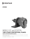
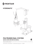
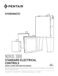
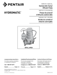
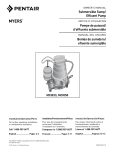
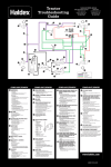
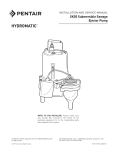
MODEL CMV5A-11 SEWAGE PUMP INSTALLATION AND SERVICE MANUAL WITH PARTS LIST NOTE! To the installer: Please make sure you provide this manual to the owner of the equipment or to the responsible party who maintains the system. Part # 23833A314 | © 2012 Pentair Pump Group, Inc. | 11/08/12 IMPORTANT INSTRUCTIONS BEFORE INSTALLATION • Running the pump continuously. • Pumping chemicals or corrosive liquids. Failure to follow these instructions may cause serious bodily injury and/or property damage. • Pumping gasoline or other flammable liquids. CALIFORNIA PROPOSITION 65 WARNING: WARNING: Risk of electrical shock – This pump is supplied with a grounding conductor and grounding type attachment plug. To reduce the risk of electrical shock, connect only to a properly grounded grounding type receptacle. This pump has not been investigated for use in swimming pool/fountain areas. Read instructions before installing pump. This product and related accessories contain chemicals known to the State of California to cause cancer, birth defects or other reproductive harm. PIPING PVC pipe is shown in the illustrations, but galvanized steel or copper pipe may be used if desired. All piping must be clean and free of all foreign matter to prevent clogging. 1.Before installing or servicing your pump, BE CERTAIN pump power source is disconnected. 2.Installation and electrical wiring must adhere to state and local codes and must be complete before priming pump. Check appropriate community agencies, or contact local electrical and pump professionals. INSTALLATION Be certain sump basin is clean and all power to pump is shut off. 3.CALL AN ELECTRICIAN WHEN IN DOUBT. Pump should be connected to a separate 15 amp circuit breaker or 15 amp fuse block. Plugging into existing outlets may cause low voltage at motor, causing blown fuses, tripping of motor overload, or burned-out motor. General materials needed: • One can PVC cement (read instructions carefully) 4.A permanent grounded connection from the pump to the grounding bar at the service panel is mandatory. Sump pump comes with a grounding conductor and a grounding type attachment plug. Do not connect pump to a power supply until permanently grounded. For maximum safety, ground pump to a circuit equipped with a fault interrupter device. • Three 2" male PVC adapters. • Enough 2" rigid PVC pipe and couplings to reach from bottom of sump basin to discharge. • One 2" PVC elbow. • One 2" free-flow check valve #CV-200P. • One shut-off gate. 5.Voltage of power supply must match the voltage of the pump. All Myers sewage pumps are factory preset to 115V, 60 Hz. • Basin with gasketed cover and vent. 6.Before installing pump, clear sump basin of any water, debris, or sediment. WARNING: Sump basin must be vented in accordance with local plumbing codes. Myers sewage pumps are not designed for and CANNOT be installed in locations classified as hazardous in the National Electric Code, ANSI/NFPA 70. • Pipe wrench • Slot screwdriver • 24-tooth hacksaw, knife or round file Tools needed for all pump installations: 1.Thread one 2" male PVC adapter into pump discharge opening. NOTE: DO NOT use thread compound or overtighten adapter or discharge pipe. Cement enough PVC pipe and couplings onto adapter to reach out of sump basin. 7.The sump basin should be 18" in diameter and made of plastic, fiberglass, or concrete. It must be equipped with a gasketed, properly vented cover. Consult local plumbing codes for correct vent size. 2.Lower pump into sump basin as near to the center as possible. Cement 2" PVC elbow onto open end of discharge pipe. Cement a section of 2" PVC pipe to open end of elbow. 8.The following may cause severe damage to pump and will void warranty: • Using an extension cord. • Cutting off the ground pin or using an adapter fitting. • Working on pump or switch while plugged in. • Removing motor housing, unscrewing impeller, or otherwise removing impeller seal. 23833A314 11/08/12 3.Fasten check valve onto open end of discharge pipe. Thread a 2" male PVC adapter into either side of 2" shut-off gate valve. 4.Fasten open end of check valve onto a section of PVC pipe. Cement open end of PVC pipe onto 2" shut-off gate valve with male PVC adapters. 2 5.Cement final section of PVC pipe to open end of shut-off gate valve. Fill sump basin with water and plug in pump. Pump should turn on at approximately 15" water level. Perform several ON-OFF cycles to assure satisfactory operation. 6.Install gasketed cover and vent onto basin. TROUBLESHOOTING CHECKLIST CAUTION: SHUT OFF POWER TO PUMP PROBLEM Pump does not run or hums. POSSIBLE CAUSES • Line circuit breaker is off, or fuse is blown or loose. • Water level in sump has not reached turn-on level as indicated in installation drawing. • Pump cord is not making contact in receptacle. • Float is stuck. It should operate freely in basin. • If all the above are OK, then the motor winding may be open. Pump runs but does not deliver water. • Check valve is installed backward. Arrow on valve should point in direction of flow. • Discharge shut-off valve (if used) may be closed. • Pump is air-locked. Start and stop several times by plugging and unplugging cord. Check for clogged vent hole in pump case. • Impeller or volute openings are fully or partially clogged. Remove pump and clean. • Inlet holes in pump base are clogged. Remove pump and clean the openings. • Vertical pumping distance is too high. Reduce distance or resize pump. Pump runs and pumps out sump, but does not stop. • Float is stuck in up position. Be sure float operates freely in basin. • Defective float switch. Replace float switch. Pump runs but delivers only a small amount of water. • Pump is air-locked. Start and stop several times by plugging and unplugging cord. Check for clogged vent hole in pump case. • Vertical pumping distance is too high. Reduce distance or resize pump. • Inlet holes in pump base are clogged. Remove pump and clean the openings. • Impeller or volute openings are fully or partially clogged. Remove pump and clean. • Pump impeller is partially clogged with foreign matter, causing motor to run slow and overload. Remove pump and clean. Fuse blows or circuit breaker trips when pump starts. • Pump impeller is partially clogged with foreign matter, causing motor to run slow and overload. Remove pump and clean. • Motor stator may be defective. • Fuse size or circuit breaker may be too small. Must be 15 amps. • Impeller or volute openings are fully or partially clogged. Remove pump and clean. Motor runs for a short time, then stops. • Inlet holes in pump base are clogged. Remove pump and clean the openings. • Pump impeller is partially clogged with foreign matter, causing motor to run slow and overload. Remove pump and clean. • Motor stator may be defective. • Impeller or volute openings are fully or partially clogged. Remove pump and clean. 3 23833A314 11/08/12 REPAIR PARTS 1 4 16 6 5 7 2 8 3 18 9 12 10 13 14 15 11 23833A314 11/08/12 4 REPAIR PARTS LIST Ref. No. Description 1 Cord, Electric, 20 ft. 2 Wire with Terminals, 4-1/2" Lg. 3 Switch, Float, Mechanical 4 Cap, Motor 5 Ring, O 6 Screw, Machine, 1/4" x 7/8" Long 7 Oil, Transformer 8 Housing & Stator 9 Seal, Shaft, Rotary 1/2" 10Impeller 11Loctite®, Impeller Threads 12 Screw, Machine, Flat Head #10-24 x 5/8" Lg. 13 Case, Volute Top 14 Case, Volute Bottom 15 Screw, Self Tapping, #10 x 1" Lg. 16 Plug, Pipe, 1/4" Countersunk 17 Tie, Plastic 18 Screw, Self Tapping #10 x 1/2" Lg. 19Instructions 5 Part Number Quantity 21628A044 1 09859A800 1 25798A500 1 24431C071 1 05876A146 1 18475A003 6 24709110000 48 oz. 24446C013 1 21607A001 1 21610B000 1 14550A001 1 Drop 07597A030 4 24637D000 1 24638D000 1 09822A036 8 05022A056 1 17190A008 1 09822A006 1 23833A314 1 23833A314 11/08/12 COMPLETE PUMP INSTALLATION Grounded type 115 volt receptacle. Minimum height of 4 feet above floor. 2” shut-off gate valve Sealed cover (top view of sump basin) 2” male PVC adapters 2” free-flow check valve #CV-200P 2” or 3“ vent pipe as required by local code 2” PVC elbow 10-1/2” Minimum Sump basin 18” in diameter made of plastic, fiberglass or concrete 2” discharge pipe. May be PVC, galvanized steel, or copper piping Bottom of inlet pipe Turn-on level 17” Minimum 1/8” Relief hole (5” above pump opening) 7” Turn-off level 13” Mechanical float switch 23833A314 11/08/12 6 THIS PAGE INTENTIONALLY LEFT BLANK STANDARD LIMITED WARRANTY Pentair Myers® warrants its products against defects in material and workmanship for a period of 12 months from the date of shipment from Pentair Myers or 18 months from the manufacturing date, whichever occurs first – provided that such products are used in compliance with the requirements of the Pentair Myers catalog and technical manuals for use in pumping raw sewage, municipal wastewater or similar, abrasive-free, noncorrosive liquids. During the warranty period and subject to the conditions set forth, Pentair Myers, at its discretion, will repair or replace to the original user, the parts that prove defective in materials and workmanship. Pentair Myers reserves the right to change or improve its products or any portions thereof without being obligated to provide such a change or improvement for prior sold and/or shipped units. Start-up reports and electrical schematics may be required to support warranty claims. Submit at the time of startup through the Pentair Myers website: http://forms.pentairliterature.com/startupform/startupform.asp?type=m. Warranty is effective only if Pentair Myers authorized control panels are used. All seal fail and heat sensing devices must be hooked up, functional and monitored or this warranty will be void. Pentair Myers will cover only the lower seal and labor thereof for all dual seal pumps. Under no circumstance will Pentair Myers be responsible for the cost of field labor, travel expenses, rented equipment, removal/reinstallation costs or freight expenses to and from the factory or an authorized Pentair Myers service facility. This limited warranty will not apply: (a) to defects or malfunctions resulting from failure to properly install, operate or maintain the unit in accordance with the printed instructions provided; (b) to failures resulting from abuse, accident or negligence; (c) to normal maintenance services and parts used in connection with such service; (d) to units that are not installed in accordance with applicable local codes, ordinances and good trade practices; (e) if the unit is moved from its original installation location; (f) if unit is used for purposes other than for what it is designed and manufactured; (g) to any unit that has been repaired or altered by anyone other than Pentair Myers or an authorized Pentair Myers service provider; (h) to any unit that has been repaired using non factory specified/OEM parts. Warranty Exclusions: Pentair MYERS MAKES NO EXPRESS OR IMPLIED WARRANTIES THAT EXTEND BEYOND THE DESCRIPTION ON THE FACE HEREOF. Pentair MYERS SPECIFICALLY DISCLAIMS THE IMPLIED WARRANTIES OF MERCHANTABILITY AND FITNESS FOR ANY PARTICULAR PURPOSE. Liability Limitation: IN NO EVENT SHALL Pentair MYERS BE LIABLE OR RESPONSIBLE FOR CONSEQUENTIAL, INCIDENTAL OR SPECIAL DAMAGES RESULTING FROM OR RELATED IN ANY MANNER TO ANY Pentair MYERS PRODUCT OR PARTS THEREOF. PERSONAL INJURY AND/OR PROPERTY DAMAGE MAY RESULT FROM IMPROPER INSTALLATION. Pentair MYERS DISCLAIMS ALL LIABILITY, INCLUDING LIABILITY UNDER THIS WARRANTY, FOR IMPROPER INSTALLATION. Pentair MYERS RECOMMENDS INSTALLATION BY PROFESSIONALS. Some states do not permit some or all of the above warranty limitations or the exclusion or limitation of incidental or consequential damages and therefore such limitations may not apply to you. No warranties or representations at any time made by any representatives of Pentair Myers shall vary or expand the provision hereof. 1101 MYERS PARKWAY 490 Pinebush Road, Unit #4 ASHLAND, OHIO, USA 44805 CAMBRIDGE, ONTARIO, CANADA N1T 0A5 419-289-1144800-363-PUMP WWW.FEMYERS.COM Warranty Rev. 12/13