1
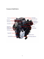
KODIAK MARINE
Marine Operators Manual
2.4L 4.3L 5.7L 6.0L AND 6.2L LS3 ENGINES
KEM EQUIPMENT INC
10800 SW HERMAN RD
TUALATIN, OR. 97062
PHONE (503) 692-5012
FAX (503) 692-1098
KM 10701 REV A
2
IMPORTANT DEFINITIONS
A WARNING indicates a potentially hazardous situation that, if not avoided,
could result in death or serious injury.
A CAUTION indicates a potentially hazardous situation that, if not avoided,
could result in damage to engine or property.
A NOTE provides other helpful information that does not fall under the
warning or caution categories.
WARNING—DANGER OF DEATH OR PERSONAL INJURY
WARNING: FOLLOW INSTRUCTIONS
Read this entire manual and all other publications pertaining to the work to
be performed before installing, operating, or servicing this equipment.
Failure to follow instructions can cause personal injury and/or property
damage
WARNING: FOLLOW ALL SAFETY PRECAUTIONS AND
REGULATIONS
Anyone involved in operation of equipment shall be familiar with the
information in the warnings, cautions and notes. These safety precautions
are mandatory and used to augment formal safety (U.S. Coast Guard)
regulations. Anyone operating this equipment should become thoroughly
familiar with details of operation of the equipment. Such knowledge,
constantly and properly practiced is the only method for ensuring safety as
well as reliable and economical equipment. In any boating situation, common
sense and logic rule the waterways.
WARNING: ELECTRICAL SHOCK HAZARD
The ignition system can cause severe shock if proper precautions are not
taken.
WARNING: OVER-SPEED PROTECTION
The engine is equipped with an over-speed protection device to protect
against runaway or damage to the engine with possible personal injury, loss
of life, or property damage. Diagnostic codes such as over temperature or
low oil pressure may cause engine speed reduction.
3
WARNING: PROPER USE
Any unauthorized modifications to or use of this engine outside its specified
mechanical, electrical, or other operating limits may cause personal injury
and/or property damage, including damage to the engine. Any such
unauthorized modifications: (i) constitute "misuse" and/or "negligence"
within the meaning of the product warranty thereby excluding warranty
coverage for any resulting damage, and (ii) invalidate product certifications
or listings.
CAUTION: POSSIBLE DAMAGE TO ENGINE OR PROPERTY
CAUTION: BATTERY CHARGING
To prevent damage to a control system that uses an alternator or batterycharging device, make sure the charging device is turned off before
disconnecting the battery from the system.
CAUTION: ELECTROSTATIC DISCHARGE
Electronic controls contain static-sensitive parts. Observe the following
precautions to prevent damage to these parts.
-Discharge body static before handling the control (with power to the control
turned off, contact a grounded surface and maintain contact while handling
the control).
-Avoid all plastic, vinyl, and Styrofoam (except antistatic versions) around
printed circuit boards.
-Do not touch the components or conductors on a printed circuit board with
your hands or with conductive devices.
CAUTION: WELDING When welding on the vessel, disconnect the
battery switch along with the connectors for the Engine Control Module
(ECM). If left connected there is a chance of damage to the ECM.
4
WARNING: BATTERY GROUNDING: Do not connect battery ground or
any accessory ground wires to the starter mounting bolts. Doing so can
cause a loose bolt situation over time that will cause starter failure or a
possible damaged engine block.
WARNING: CARBON MONOXIDE EXPOSURE
Carbon Monoxide is an odorless, colorless and tasteless gas that cannot be
smelled, seen or tasted. Over exposure to carbon monoxide gas may lead to
brain damage, unconsciousness or even death.
Carbon Monoxide is a hazardous gas that is produced when items containing
carbon are burned. Items such as wood, charcoal, gasoline, natural gas, propane,
and petroleum products such as oil. Carbon Monoxide is found in many areas and
is produced by all types of internal combustion engines, heaters, charcoal grills,
and any other open flame appliances. There are many possible situations for the
accumulation of carbon monoxide to occur in your vessel. Wind direction, boat
speed, and being close to other vessels are just a few of the possible ways that
would permit exposure to carbon monoxide gases. It is important that regular
inspections of the exhaust system and the engine’s fresh air vents are clean and
free of obstructions. Check that all maintenance is properly performed by a
qualified technician. Adequate air ventilation in all areas of your boat is necessary
in order to prevent build-up of carbon monoxide gas.
5
Table of Contents
Introduction
Safety Summary
How to use this manual
Page 8-9
Engine Identification
Engine ID
Warranty Card
Component ID
Page 10-13
Pre Operational Inspection
Engine fluid levels
Belts
Battery connections
Hoses
Flame Arrestor
Malfunction Indicator Light (MIL)
Page 14-16
Starting the Engine
Starting Mode Fuel injection
Clear Flood
Cold Start
Page 17-18
Stopping the Engine
Normal Conditions
Abnormal conditions (overheating)
Page 19
Maintenance Instructions
General Engine Specifications
Quick Reference Guide
Maintenance Schedule
Page 20-26
Changing Engine Oil and Filter
Engine Oil Quality
Engine Oil recommendations
Oil Filter
Page 27-28
Engine Flame Arrestor
Clean or Replace Flame Arrester
Page 28
Cooling System
Heat Exchanger
Coolant Level
Serpentine Belt
Page 29-30
6
Fuel Injection System
Fuel Filter
Fuel Recommendation
Fuel Type
Fuel Quality Changes
Power Loss at Higher Elevations
Page 31-32
Ignition System
Page 33
Troubleshooting
Engine Does Not Crank
Engine Will Crank Intermittently
When the Engine Makes a Stuttering or Chattering Noise
Engine Cranks But Does Not Start
Engine Runs Hot
Clear Flood Mode
Emissions
Page 34-37
Storage
Short Term Lay-up
Long Term Lay-up
Page 38
Periodic Maintenance Inspections
100, 400, 800, 900, Hour Inspections
Page 39-40
Warranty
Page 41-46
On Board Diagnostic (OBD) System Check
Page 47-48
Diagnostic Codes
Page 49-53
Service Dealer Locations
United States, Canada, Russia
Page 54-55
Wiring Diagrams
Page 56-60
7
INTRODUCTION
KEM Equipment, Inc. is pleased that you have selected a Kodiak engine for your
requirements. KEM Equipment, Inc. takes great pride in our tradition of quality
products produced from the GM Powertrain line of marine gasoline fuel engines.
KEM Equipment, Inc. engines are inspected and tested before leaving the factory.
However, certain checks should be made before placing the engine into regular
service. Please read the initial start-up inspection requirements in the
Maintenance section of this manual.
This Marine Operators Manual covers the 2.4L, 4.3L, 5.7L, 6.0L AND THE 6.2L
LS3 Marine Engines. In this manual we have included tables for General Engine
Specifications and tables for General Maintenance. Using this Manual will help you
get acquainted with your engine and its functions, as well as help with routine
service and maintenance to keep your Kodiak Marine Engine performing to its full
potential. General engine specifications and quick reference guides starts on page
20.
KEM Equipment Inc. reserves the right to discontinue models or accessories at
any time or to change specifications or designs without notice and without incurring
obligation.
Please read and follow any and all specific Warnings, Cautions, and Notations
contained in this text.
KEM Equipment, Inc., / Kodiak Marine reserves the right to request any pertinent
maintenance information of your engine prior to authorization of warranties. Overall
safety and equipment reliability depend on continuous observation of sound
operating practices. Always observe required scheduled maintenance activities as
outlined. Never attempt to correct problems or repairs for which you are not
qualified. At the end of this manual, you will find a list of qualified Kodiak Marine
service dealers to assist you in your area.
WARNING:
-Always STOP the engine before refueling.
-Always STOP the engine prior to any inspection / check or repair work.
-Always maintain proper ventilation when working around gas or oil.
-Always run the bilge blower for a minimum of 10 minutes prior to starting
the engine.
-Do not stand close or hover over the engine prior to starting.
Ensure all safety guards are in place prior to starting the engine.
8
How to Use this Manual
This manual is designed to help you get to know your engine and become familiar
with it’s various controls. During instruction, you will learn how to take care of your
engine and what services need to be performed to keep it in excellent running
condition. The table of contents will assist you in locating a specific subject. Please
contact a service dealer if you have reached a point of needing further instruction.
Any un-authorized work can void any potential warranties. We urge you to read
this manual prior to start up of the engine.
KEM Equipment, Inc. engines are built with a variety of standard and/or optional
components to suit a broad range of customer requirements. This manual does
not identify equipment as standard or optional. All the equipment described in this
manual may or may not be found on your engine. The description and
specifications contained in this manual were in effect at the time of publication.
9
ENGINE IDENTIFICATION
Model Identification
An identification placard is affixed to the engine. The label contains the engine
family number and a model, which identifies the engine from other KEM engines.
The engine model number and serial number are required when seeking
information concerning the engine and/or ordering replacement service parts.
This manual covers the 2.4L 4.3L 5.7L 6.0L and the 6.2L LS3 Marine Engines.
Fill in the information from your engine in the above representation of the engine
tag for future reference.
MODEL: This is the part number for the engine, and this number should be
recorded for ease of obtaining information or parts for this engine.
SERIAL NUMBER: This number identifies each individual engine. This number
should also be recorded for the ease of obtaining information for this engine. If you
have a request or need to order service parts, this serial number will be requested
to aid our parts dept in fulfilling your order. The serial number will confirm that you
are ordering the correct parts for your engine.
WARRANTY CARD: The warranty card shipped with your engine must be
filled out and returned to KEM within 30 days of receipt of your new vessel.
This warranty card will also need to be filled out and returned if a re-power is
being performed with a new Kodiak engine. Failure to fill out and return your
warranty card to KEM within this time period can void all warranties related
to this engine. This warranty card also helps to identify your engine and its
related parts.
10
Component Identification
11
These illustrations show the general location of engine controls and their
functions. These illustrations will help identify where these parts are located
on the engine. Locations will vary from engine to engine.
12
Parts and Service
Replacement parts can be obtained through your local Kodiak engine dealer.
Kodiak dealers are equipped to perform major and minor repairs. They are anxious
to see that all of your maintenance and service needs are quickly and courteously
completed. Please contact KEM Equipment Inc./Kodiak Marine regarding any
favorable or un-favorable experiences with our service dealers.
The engine model number and serial number will be required when seeking
information and/or ordering parts. There is a list of service dealers located at the
very end of this manual.
Technical support for Kodiak Marine engines can be obtained by contacting KEM
Equipment Inc.
Service Literature
By contacting our Parts Department you can purchase parts and service manuals
for Kodiak Marine engines. 503-692-5012
WARNING: The bilge can accumulate explosive fumes. The bilge
blower will evacuate the fumes. The bilge blower must be run for a minimum
of 10 minutes prior to cranking the engine.
WARNING: Do not start or run the engine in a closed or poorly
ventilated area where exhaust gases may accumulate. All internal
combustion engines give off various fumes and gases while running. Avoid
breathing these gases as they may contain poisonous carbon monoxide and
other gases, which can endanger your health or life if inhaled steadily for a
few minutes.
CAUTION: If the engine stalls or falters during starting, wait 3 to 4
seconds before reengaging the starter. This will prevent possible damage
to the starter or the engine. Do NOT operate the starter for periods longer
than 5-8 seconds at a time. An interval of at least 1 minute should be
observed between cranking periods to protect the starter from overheating.
13
PRE-OPERATIONAL INSPECTION
WARNING: Remove the key from the ignition prior to any engine
check or operation. Do not energize any engine prior to performing any of
the following.
Your KODIAK Marine Engine was inspected and test ran before leaving the
factory. Before operating a new engine, you must follow any pre-operational
instruction.
1. Open the engine hatch cover and let the compartment air out for at least ten
minutes.
2. Always make sure you are working in a well-ventilated area when around
gasoline.
3. Check engine oil level, remove dipstick wiping clean, and recheck your oil level.
4. Inspect the oil and fuel filters for tightness and make sure there are no leaks
around these filters.
5. Check coolant level – refill to the appropriate levels.
6. Check for any oil, coolant, or fuel leaks.
CAUTION: Follow any leaks and repair any abnormal leakage before
continuing.
7. Inspect the battery connections for corrosion, clean as necessary.
8. Check the battery fluid level and state of charge, fill as needed.
9. Inspect the spark arrester for any obstructions (Bugs, leaves etc.,) clean or
replace as needed.
10. Check coolant Hoses for Leaks (follow any leaks and repair).
NOTE: It is suggested to use Baking Soda and water to safely clean any
corrosion around the Battery connections.
NOTE: If the engine is equipped with a stern or jet drive it must be in neutral
prior to starting the engine. Starting the engine with the drive engaged
imposes unnecessary strain on the battery, starter and driven components.
Inspect the spark arrester for any obstructions (bugs, leaves etc.). Clean or
replace as needed.
14
Check the exterior of the heat exchanger. Follow and fix any leaks before
continuing.
11. Check the alternator belt for any extra play; adjust as necessary. Does not
apply to all engines.
12. Tighten all loose nuts and bolts. Check for any loose pieces and tighten as
necessary.
13. Start and run the bilge blower for at least 10 minutes.
14. Replace the engine cover.
CAUTION: All water must be drained from the raw water side of the
heat exchanger when surrounding environment temperature is below
32°F/0°C.
MALFUNCTION INDICATOR LIGHT
Caution-
Notice To Builder/Installer
This engine requires use of
a MIL.
A MIL (Malfunction Indicator Lamp) must be installed with this engine to be in
compliance with EPA and CARB regulations.
There are two lights on the dash to indicate engine related problems. The operator
is responsible to scan for illuminated bulbs during the course of engine operation.
The first indicator is the Check Engine Light. The MIL conveys to the operator that
a fault exists that is related to the engine’s control system. When this light is
illuminated, a fault code has been set that requires immediate attention or engine
component damage could conceivably occur.
Please stop operation of engine as soon as safely possible. Request that a
technician inspect the fault code setting. He or she will connect a scan tool to
determine the cause of the MIL illuminating, repair the problem, and clear the
codes. The MIL related codes are caused by sensor output and/or conditions that
adversely affect the operational output of the engine. Some of the components that
can cause problems are: crank sensor, cam sensor, fuel injectors, regulators,
ignition system and Manifold Air Pressure (MAP) sensor.
NOTE: If the Check Engine light is illuminated, it will remain on until the
problem is corrected and the engine has gone through three consecutive
warm up cycles, or if the light has been cleared by a service technician with
a scan tool. A warm up cycle is a starting temperature close to ambient
increasing to operating temperature.
15
The second indicator is the Check Gauges light. This bulb will illuminate when a
non-emissions related issue occurs. Items that can cause these codes are high or
low oil pressure and coolant temperature and various power relay operation,
system voltage etc. The lighting of this fault indicator would indicate to the operator
that the gauges for oil pressure and coolant temperature should be checked
immediately and action taken to eliminate engine damage. There are safeties in
the calibration that will reduce engine speed if the sensor output is out of the
normal range (low oil pressure when the engine is at rated speed for instance). If
the engine should turn off for no apparent reason check this lamp. This light will
clear on it’s own if the fault clears and the ignition switch is turned off then back on.
If this light turns off on it’s own, the issue will stay in memory for 40 warm up cycles
or until a technician clears it manually with a scan tool.
NOTE: The lamps will not flash the error codes. To retrieve and reset the
error codes a diagnostic scan tool is required. Some vessel manufacturers
are using CAN-BUS displays that can retrieve the error codes, but cannot
clear them. See the vessel manufacturers instructions to retrieve the error
codes with their device.
16
STARTING THE ENGINE
Prior to starting the engine the following must be performed.
1. Check engine oil level.
2. Check for fuel leaks.
3. Run bilge blower for a minimum of 10 minutes.
4. Check Coolant level.
5. Check bilge for excess water before starting engine.
WARNING: The bilge can accumulate explosive fumes. The bilge
blower will evacuate the fumes. The bilge blower must be run for a minimum
of 10 minutes prior to cranking the engine.
WARNING: Do not start or run the engine in a closed or poorly
ventilated area where exhaust gases may accumulate. All internal
combustion engines give off various fumes and gases while running. Avoid
breathing these gases as they may contain poisonous carbon monoxide and
other gases, which can endanger your health or life if inhaled steadily for a
few minutes.
CAUTION: The bilge should be checked for excess water prior to
starting the engine. Excess water can cause premature starter failure and
damage to other engine components.
NOTE: This engine is equipped with a computer controlled starter circuit. It
is not necessary to hold the ignition switch in start mode until the engine
starts, although holding the key on will not cause any issues.
CAUTION: If the engine stalls or falters during starting, wait 3 to 4
seconds before re-engaging the starter. This will prevent possible damage to
the starter or the engine. Do NOT operate the starter for periods longer than
5-8 seconds at a time. An interval of at least 1 minute should be observed
between cranking periods to protect the starter from overheating.
17
STARTING MODE – FUEL INJECTION
With the ignition switch in the ON position, before engaging the starter, the ECM
energizes the fuel pump relay for 10 seconds allowing the fuel pump to build
pressure. The ECM uses the engine coolant temperature (ECT), the throttle
position (TPS), and the manifold absolute pressure (MAP) sensors to determine
the proper air/fuel ratio for starting. The ECM controls the amount of fuel delivered
in the starting mode by changing the pulse width of the injectors.
CLEAR FLOOD – FUEL INJECTION
If the engine becomes flooded clear the engine by opening the throttle to 100
percent. When the pedal position sensor (PPS) is at wide-open throttle, the ECM
reduces the injector pulse width in order to increase the air to fuel ratio. The ECM
holds this injector rate as long as the throttle stays wide open and the engine
speed is below a predetermined RPM. If the throttle is not held wide open, the
ECM returns to the starting mode.
COLD ENGINE START
On a cold engine start, the engine idle speed will be elevated until the coolant
temperature reaches operating temperature. As the engine temperature increases
the idle speed will gradually decrease, this is a normal engine control function.
18
STOPPING THE ENGINE
NORMAL CONDITIONS
Let the engine idle for at least one minute prior to stopping the engine to reduce
residual heat in engine components. Not doing this will not harm anything, but
gives the engine a chance to reduce the temperature of many components.
STOPPING THE ENGINE UNDER ABNORMAL CONDITIONS (Overheating)
1. Put engine in NEUTRAL.
2. Place gearshift or bucket control lever in Neutral.
3. Turn key to the OFF position and remove the key from the ignition.
4. If the engine is overheating due to loss of coolant, it is best to stop the engine
immediately.
5. Check and adjust the oil and coolant levels.
6. Once the engine has cooled considerably, add your coolant slowly until the heat
exchanger is full.
WARNING: Allow the engine to cool at least a few minutes before
attempting to remove the heat exchanger cap. Cover the cap with a thick
cloth and slowly turn counterclockwise allowing the pressure to release
SLOWLY. When pressure has been completely released, push down on the
cap, turn and remove.
CAUTION: Do not add coolant until the engine has returned to normal
temperature. (When you can place your hand on the engine without burning
is usually a good indication).
19
MAINTENANCE INSTRUCTIONS
CAUTION: Neglecting proper maintenance can cause premature
component failures.
Initial Start Up Maintenance
The initial start-up checks must be made before entering the engine into service.
Please refer to the Maintenance Schedule on page 26 and perform the initial startup operations in the sequence shown in column 1.
Routine Maintenance
Routine maintenance provides the best solution for making sure that the engine is
ready when you are. The following are some routine service points:
• Keep the fuel tank filled. A full tank of fuel reduces the possibility of condensation
forming in the fuel tank and moisture entering the fuel system.
• Make frequent checks for engine oil, fuel and coolant leaks
• Repair any oil, fuel or coolant leaks
• Check battery condition and cables frequently clean as necessary
• Keep the engine air filter and/or spark arrestor clean
• Monitor engine coolant temperature
• Monitor engine oil pressure and fuel pressure.
• Check voltmeter and charging system
• Lubricate Drive Shaft universal joints as described in scheduled preventive maintenance
section (some applications)
Knowing normal gauge values will help you determine abnormal conditions.
Maintenance Schedule
Refer to the Maintenance Schedule on page 26 to ensure that all of the
maintenance items listed are checked and replaced at the recommended hours.
20
2.4L/147
GENERAL ENGINE SPECIFICATIONS
ENGINE
2.4L
TYPE
L4
DISPLACEMENT
2405cc / 147 CID
VALVE CONFIGURATION
SINGLE O/H CAM
VALVE LIFTERS
HYDRAULIC FOLLOWER
BORE X STROKE INCHES
3.44X3.94
MAIN BEARING CAPS
2 BOLT
BALANCE METHOD
INTERNAL
INTAKE MANIFOLD
SIDE DRAFT
FIRING ORDER
1-3-4-2
OIL CAPACITY W/FILTER
4.5 QUARTS
FUEL TYPE
GASOLINE
ENGINE ROTATION
CCW FLYWHEEL END
QUICK REFERENCE CHART
ENGINE
2.4L
OIL FILTER ORIGINAL LOCATION
PF-47 OR NAPA # 1040
WATER SEPARATOR FILTER
NAPA # 3225
SPARK ARRESTER
KM 10272
SPARK PLUGS
93206675 OR NGK BPR6ES
SPARK PLUG GAP
.040
SERPENTINE BELT
NAPA # 25-060355
PCV VALVE
25042116
FUEL PRESSURE
3 BAR 43 PSI
ENGINE OIL
10W-40 GF-4 ILSAC SPECS
21
4.3L/ 262
GENERAL ENGINE SPECIFICATIONS
ENGINE
4.3L
TYPE
V6
DISPLACEMENT
262 CID
VALVE CONFIGURATION
PUSH ROD
VALVE LIFTERS
HYDRAULIC ROLLER
BORE X STROKE INCHES
4.00 X 3.48
MAIN BEARING CAPS
2 BOLT
BALANCE METHOD
EXTERNAL
FIRING ORDER
1-6-5-4-3-2
OIL CAPACITY W/FILTER
4.5 QUARTS
FUEL TYPE
GASOLINE
ENGINE ROTATION
CCW FLYWHEEL END
QUICK REFERENCE CHART
OIL FILTER ORIGINAL LOCATION
PF-52 W / REMOTE NAPA # 21515
WATER SEPARATOR FILTER
NAPA # 3225
SPARK ARRESTER
KM 10272
SPARK PLUGS
25162556 OR AC Delco 41-993
SPARK PLUG GAP
.062
V -BELTS (2)
NAPA # 15435
PCV VALVE
FIXED ORIFICE
FUEL PRESSURE
4 BAR 58 PSI AT FUEL RAIL
ENGINE OIL
10W-40 GF-4 ILSAC SPECS
22
5.7L/350
GENERAL ENGINE SPECIFICATIONS
TYPE
L-31
DISPLACEMENT
5.7L 350ci
VALVE CONFIGURATION
OHV TWO PER CYL
VALVE LIFTERS
HYD ROLLER
BORE X STROKE
4.00 IN X 3.48 IN
MAIN BEARING CAPS
2 BOLT
BALANCE METHOD
EXTERNAL
FIRING ORDER
1-8-4-3-6-5-7-2
OIL CAPACITY W/O FILTER
6 QTS
FUEL TYPE
GASOLINE
ENGINE ROTATION
CCW FLYWHEEL END
QUICK REFERENCE CHART
OIL FILTER ORIGINAL
LOCATION
PF-25
WATER SEPARATOR FILTER
NAPA # 3225
SPARK ARRESTOR
A7660
SPARK PLUGS
25162556 AC Delco 41-101
SPARK PLUG GAP
.062
V-BELTS (2)
NAPA # 15435
PCV VALVE
CV-769 C
FUEL PRESSURE
4 BAR 58 PSI AT FUEL RAIL
ENGINE OIL
10W-40 GF-4 ILSAC SPECS
23
W / REMOTE NAPA # 21515
6.0L/ 364
GENERAL ENGINE SPECIFICATIONS
TYPE
L96
DISPLACEMENT
6.0L 364ci
VALVE CONFIGURATION
OHV TWO PER CYL
VALVE LIFTERS
HYD ROLLER
BORE X STROKE
101.6 mm x 92 mm
MAIN BEARING CAPS
6 BOLT
BALANCE METHOD
INTERNAL/EXTERNAL
FIRING ORDER
1-8-7-2-6-5-4-3
OIL CAPACITY W/O FILTER
6 QTS
FUEL TYPE
GASOLINE
ENGINE ROTATION
CCW FLYWHEEL END
QUICK REFERENCE CHART
OIL FILTER ORIGINAL
LOCATION
PF-46 W / REMOTE NAPA # 21515
WATER SEPARATOR FILTER
NAPA # 3225
SPARK ARRESTOR
KM 10272
SPARK PLUGS
12621258 AC Delco 41-985
SPARK PLUG GAP
.062
SERPENTINE BELT
NAPA # 25-060770
PCV VALVE
FIXED ORIFICE
FUEL PRESSURE
REGULATOR/FILTER
NAPA # 3737
FUEL PRESSURE
4 BAR 58 PSI AT FUEL RAIL
ENGINE OIL
5W-30 GF-4 ILSAC SPECS
24
6.2L LS3/376
GENERAL ENGINE SPECIFICATIONS
Engine
6.2L
TYPE
V-8
DISPLACEMENT
376 CID
VALVE CONFIGURATION
OVERHEAD VALVES
VALVE LIFTERS
HYDRAULIC ROLLER
BORE X STROKE INCHES
103.25 X 92MM
INTAKE MANIFOLD
COMPOSITE
FIRING ORDER
1-8-7-2-6-5-4-3
FUEL SYSTEM
FUEL INJECTED
OIL CAPACITY W/REMOTE FILTER
5.5 QTS
COOLANT CAPACITY
4 GAL
BORE CENTER
111.76 MM
FUEL TYPE
PREMIUM 91 OR BETTER
ENGINE ROTATION
CCW FLYWHEEL END
QUICK REFERENCE CHART
OIL FILTER ORIGINAL LOCATION
PF-48 W / REMOTE NAPA #21515
FUEL WATER SEPARATOR
NAPA # 3225
SPARK PLUGS
12621258
SPARK ARRESTER
K+N 59-5002
SPARK PLUG GAP
.062
SERPENTINE BELT
25-060658
FUEL PRESSURE REGULATOR
NAPA # 3737
FUEL PRESSURE
4 BAR 58 PSI AT FUEL RAIL
ENGINE OIL
USE ONLY MOBIL-1 5W-30
25
MAINTENANCE SCHEDULE
SERVICE INTERVAL
ENGINE CHECK POINTS
DAILY
EVERY 25
HOURS
EVERY 50
HOURS
EVERY 75 EVERY 100 EVERY 150 EVERY 200 EVERY 300 EVERY 400
HOURS
HOURS
HOURS
HOURS
HOURS
HOURS
GENERAL MAINTENANCE
PRIOR TO ANY SERVICE OR MAINTENANCE ACTIVITY
Inspect fuel system for leaks
Inspect engine for fluid leaks
X
Check engine oil
X
X
Replace engine oil and filter
Inspect accessory drive belts
X
Check for MIL at key on. If MIL remains
illuminated after starting (it is indicating
a fault), refer to page 48
X
X
Inspect ECM isolation mounts for cracks
and wear; replace as necessary
Inspect throttle control function
X
X
X
X
Check engine compression
ENGINE COOLANT
Check engine coolant level
X
X
Replace coolant
Inspect coolant hoses for leaks, cracks,
swelling, or deterioration
X
X
X
ENGINE ELECTRICAL SYSTEM
Inspect battery for case damage and
corroded cables
X
X
X
Inspect electrical and ignition system
X
X
Replace spark plugs
FUEL SYSTEM
X
Replace fuel/water separator filter
Service
Dealer
Check fuel pressure
Inspect all fuel hoses and fittings for
leaks
X
X
AIR INTAKE
Check for leaks in air intake and filtration
system
X
X
X
Inspect flame arrestor element
Clean or replace flame arrestor element as conditions require or at 100 hours
Clean flame arrestor element
Inspect throttle body for loose bolts or
vacuum leaks
X
Inspect engine for exhaust leaks
Inspect exhaust system for cracks, leaks,
gaskets, and loose bolts
X
X
ENGINE EXHAUST SYSTEM
X
26
CHANGING ENGINE OIL AND FILTER
Under normal operating conditions, the engine oil and filter must be changed every
100 hours or every 12 months whichever occurs first. Use of premium quality oil
and filters is recommended. The oil and filter should be changed more often if the
engine is operating in severe conditions, such as dirty areas, or during cold
weather. No oil additives or break-in oil are recommended.
CAUTION: Do not operate the engine with the oil level below the
bottom of the dipstick or ‘Add’ mark on the dipstick, or above the top or ‘Full’
mark on the dipstick.
Engine Oil Level Check
The engine oil level should be checked daily. It is recommended that the oil be
checked just before the engine is started for the first time for the day. The oil level
should be between the ‘ADD’ and the ‘FULL’ marks on the dipstick.
Adding Engine Oil
It is normal to add some oil in the period of time between oil changes. The amount
will vary with the severity of operation. When adding or replacing engine oil, be
sure the oil meets or exceeds the recommended specification.
Engine Oil Quality
To achieve proper engine performance and durability, it is important that you use
only engine lubricating oils of the correct type in your engine. Quality oil also
provides maximum efficiency for crankcase ventilation systems, which reduces
pollution.
Engine Oil Recommendation
Motor oils meeting ILSAC (International Lubricant Standardization & Approval
Committee) GF-4 standards. The GM spec for this oil is 9986231. Motor oils
meeting this spec receive the API (American Petroleum Institute) starburst symbol:
27
Oil Filter
NOTE: Ensure the old filter gasket is removed prior to installing the new
filter.
The Kodiak GM Powertrain engines use an AC Delco (or equivalent) oil filter as
original equipment. An equivalent oil filter must be used when servicing the engine
(see Engine Specifications starting on page 20 for the recommended oil filter for
your engine).
The filter protects your engine from harmful, abrasive, or sludgy particles without
blocking the flow of oil to vital engine parts.
To replace the filter, use a proper filter wrench to remove the filter. Clean the filtermounting base and lightly coat the gasket surface of the new filter with engine oil.
Hand tighten the filter until the gasket contacts the base, then tighten another ½
turn. Fill the engine with the correct amount of oil, run the engine and check for oil
leaks at the drain plug and filter gasket. Tighten as necessary to stop any oil
leakage.
FLAME ARRESTER
The purpose of the flame arrestor is to contain any possible flame that gets into the
intake manifold due to an engine failure, but also serves other purposes.
CAUTION: Service the flame arrestor more frequently under severely
dusty or dirty conditions.
Your flame arrestor does not filter the air entering the engine induction system but
does act as a silencer. The flame arrester is not an actual air filter. Air that
contains dirt and grit produces an abrasive fuel mixture and can causes severe
damage to the cylinder walls and piston rings. Damage to the cylinder walls and
piston rings will cause high oil consumption and short engine life. A restricted or
dirty flame arrestor can cause a low power situation. Therefore it is extremely
important that the flame arrestor be serviced at the recommended 100 hr intervals,
or sooner depending on operating conditions.
1. Clean screen by washing with solvent.
2. Blow dry or allow dripping dry prior to installation.
3. Remove all dust and foreign matter from spark arrestor.
Make sure the flame arrestor is seated properly on the throttle body when
reinstalled. Do not operate engine without flame arrestor.
28
COOLING SYSTEM
KEM Equipment and GM Powertrain recommends the use of DEX COOL coolant
in all GM engines. A 50/50 mixture is recommended.
WARNING: Never remove the heat exchanger cap under any condition
while the engine is operating. Failure to follow these instructions could
result in damage to the cooling system, engine, or cause personal injury.
CAUTION: DO NOT add coolant or water to any engine that has
become overheated until the engine cools. Adding coolant or water to an
extremely hot engine can result in a cracked block or cylinder head.
CAUTION: DO NOT mix DEX-COOL (pink/orange colored) with
traditional (green) ethylene glycol. Refer to the mixture chart on the
container for additional antifreeze protection information. DO NOT use
alcohol or methanol antifreeze, or mix them with the specified coolant. Plain
water may be used in an emergency (except in freezing temperatures), but
replace it with the specified coolant as quickly as possible to avoid damage
to the system.
COOLANT LEVEL
Check the coolant level of the heat exchanger daily and only when the engine is
cool. Generally a good time to do this is just prior to starting the engine for the first
time each day.
Plain water may be used in an emergency and above 32 F ambient temperature,
but replace it with the specified coolant as quickly as possible to avoid freezing or
damage to the cooling system.
29
Heat Exchanger
1. Check the coolant level in the heat exchanger daily (prior to operation)
2. Make sure the coolant level is within ¾ to 1-½ inches below the filler neck seat
3. Check the condition of the rubber seal on the coolant filler cap
4. Make sure the rubber seal is clean and free of any dirt particles.
5. Make sure the filler neck is clean then replace cap.
6. Check all hoses and connections for leaks.
7. Check coolant overflow tank level, fill to cold line (prior to operation)
8. Check all hoses for cracks, frayed points, or spongy areas (replace as
necessary).
Serpentine Belt
NOTE: Make sure the belt tensioner is within the proper operating range.
Most Kodiak engines utilize serpentine belts on the front of the engine; others use
V belts. This type of belt system incorporates a belt-tensioning device that keeps
the belt at the proper tension. This belt should be checked routinely for cracks or
‘checking’ on the groove side of the belt. If cracks or ‘checking’ are apparent the
belt must be changed.
30
FUEL INJECTION SYSTEM
CAUTION: Failure to change the fuel system filter as recommended
can result in premature failure of fuel injection system components.
WARNING: Use extreme care when changing the fuel filter. Gasoline is
highly flammable and under pressure. It should not be exposed to open
flame, sparks, or hot engine components. Allow the engine to cool to
ambient temperature prior to changing fuel filters.
WARNING: Fuel is under HIGH pressure. Consult equipment service
dealer before servicing fuel system.
WARNING: The bilge can accumulate explosive fumes. The bilge
blower will evacuate the fumes. The bilge blower must be run for a minimum
of 10 minutes prior to cranking the engine.
Fuel Filter
A fuel/water separator filter is used in the fuel supply line to the engine. This helps
prevent contaminates from plugging the fuel injectors. The fuel filter is located in
the supply line between the fuel tank, fuel pump and the engine. This filter protects
the fuel injectors from debris in the fuel tank. This filter must be changed every 500
hours or every 6 months which ever occurs first.
Fuel Recommendation
WARNING: Use extreme care when changing the fuel filter. Gasoline is
highly flammable and under pressure. It should not be exposed to open
flame, sparks, or hot engine components. Allow the engine to cool to
ambient temperature prior to changing fuel filters.
31
WARNING: The bilge can accumulate explosive fumes. The bilge
blower will evacuate the fumes. The bilge blower must be run for a minimum
of 10 minutes prior to cranking the engine.
Fuel Type
2.4L 4.3L 5.7L 6.0L ENGINES
Unleaded 87 Octane or better fuel is recommended. Lower octane fuels will
reduce overall engine performance. Maximum Ethanol content is 10%.
6.2L LS3 ENGINE PREMIUM 91 MINIMUM OCTANE RECOMMENDED
Fuel Quality Changes
NOTE: Sudden changes in fuel quality, including geographical regions may
effect engine operation.
Power Loss At Higher Elevations
Fuel injected engines will lose 3.5% power for every 1000 feet the engine is
operated above sea level. All fuel injection systems installed by KEM Equipment,
Inc. are equipped with a “manifold absolute pressure sensor” (MAP Sensor). The
MAP sensor senses barometric pressure and automatically corrects the fuel
system calibration for changes in altitude. This means the air/fuel mixture will
always be optimized, regardless of elevation (or barometric pressure); however,
the engine will still lose 3.5% power for every 1000 ft. increase in elevation. All
engines will experience power loss when operated at elevations above sea level,
unless they are turbocharged or supercharged. Turbochargers and superchargers
are mechanical pumps that put extra air into the engine to make up for the lower
air density at higher elevations.
32
IGNITION SYSTEM
WARNING: High voltage ignition system. Electrical shock hazard.
WARNING: The bilge can accumulate explosive fumes. The bilge
blower will evacuate the fumes. The bilge blower must be ran for a minimum
of 10 minutes prior to cranking the engine.
Type of Ignition System
The ignition on Kodiak engines are controlled by an ECM, some use a distributor
and some are distributorless.
Turning or moving the distributor on engines so equipped, will not change the
ignition timing. If the distributor is adjusted it can cause cross firing between
cylinders.
CAUTION: Always use the recommended spark plugs for your engine.
Hotter or colder plugs, or similar plugs that are not exact equivalents to the
recommended plugs, can cause permanent engine damage, or reduce the
engines useful life, and cause many other problems such as hard starting,
spark knock and run-on. Premature failure of catalyst and exhaust emissions
may occur.
Spark plugs should be replaced at the recommended intervals as described in the
Maintenance Schedule on page 26. Use only the recommended spark plugs or an
equivalent as described in the General Specifications. Spark plug gap should be
adjusted as recommended in the General Specifications. Use the quick reference
guide for your individual engine, starting on page 20 of this manual.
33
TROUBLESHOOTING
WARNING: The bilge can accumulate explosive fumes. The bilge
blower will evacuate the fumes. The bilge blower must be run for a minimum
of 10 minutes prior to cranking the engine.
NOTE: A Malfunction Indicator Light must be installed with this engine to be
compliant with EPA and CARB regulations. Proper connections will be
covered in the wiring section of this manual.
The largest percentage of all malfunctioning equipment will be due to simple or
small problems. Most operating troubles that might be encountered with a new or
well-maintained unit will be of a minor nature. Consequently, if you experience any
problems starting or operating your engine, look for a simple cause rather than
failure of a major component. The following list should cover the most common
problems.
• Loose or corroded battery connections are more common than battery failure.
• Loose ignition wire connection – more common than distributor, coil or ignition.
• Severe weather conditions – temps below 32°F/0°C - can cause condensation on
the inside of the engine.
• Operating conditions (load changes).
• Change of periodic servicing.
• Change of grade or purity of fuel. Contaminated fuel will often foul engine
components.
• Change of operator.
Engine troubles that develop as a result of normal use and wear usually give plenty
of advance notice / warning. These problems usually develop as a result of
neglected periodic maintenance. Whenever engine performance appears less than
normal in any area, you should consult with your KODIAK dealer immediately. Do
not wait for a problem to develop. Careful attention to periodic/regular maintenance
will prevent most problems. Refer to the periodic maintenance section for
checklists.
34
Engine Does Not Crank
WARNING: Make sure there are no fuel leaks before going any further.
Clean up any spills and always work in a well-ventilated area.
WARNING: To avoid any electrical injuries always replace any
broken wires before proceeding.
WARNING: The bilge can accumulate explosive fumes. The bilge
blower will evacuate the fumes. The bilge blower must be run for a minimum
of 10 minutes prior to cranking the engine.
• Check battery cables – adjust any loose connections and clean any corrosion.
• Check battery charge.
• Check electrical leads – something may be loose or disconnected.
• Check all fuses and relays.
• Refer to Pre-Operational checklist for further checks.
Engine Will Crank Intermittently
Having to turn the key to START several times.
• Check the ignition switch for loose, corroded, disconnected or broken wires.
Tighten or replace as necessary.
When The Engine Makes A Stuttering Or Chattering Noise.
• Check the battery cables for loose connections.
• Check battery charge – charge if necessary.
• Check the starter motor and solenoid switch for loose or disconnected wires.
• Check ground connections for loose, corroded, disconnected or broken wires.
If all electrical connections have been checked for loose connections, corrosion,
broken wires and disconnected wires and after you have reviewed and performed
the Operational Instructions, contact your service dealer.
Engine Cranks But Does Not Start
CAUTION: Failure to change the fuel system filter as recommended
can result in premature failure of fuel injection system components.
35
WARNING: Use extreme care when changing the fuel filter. Gasoline is
highly flammable and under pressure. It should not be exposed to open
flame, sparks, or hot engine components. Allow the engine to cool to
ambient temperature prior to changing fuel filters.
WARNING: Fuel is under HIGH pressure, consult dealer before
servicing fuel system.
WARNING: The bilge can accumulate explosive fumes. The bilge
blower will evacuate the fumes. The bilge blower must be run for a minimum
of 10 minutes prior to cranking the engine.
• Check fuel tank level.
• See clear flood mode on page 18
• Check for signs of fuel leaks.
• Check fuel lines.
• Check fuel pressure.
• Inspect for crimps, kinks, blockage or any disconnected lines.
• Inspect for any leakage (leaks may allow air in the lines blocking fuel flow.)
• Follow and repair any leaks before continuing.
• Contact your service dealer for more advanced diagnosis
• Check fuel pressure (service dealer)
• Clean up any fuel spills or leaks prior to attempting to start the engine.
Engine Runs Hot
WARNING: Never remove the radiator cap under any condition while
the engine is operating. Failure to follow these instructions could result in
damage to the cooling system, engine, or cause personal injury.
WARNING: The bilge can accumulate explosive fumes. The bilge
blower will evacuate the fumes. The bilge blower must be run for a minimum
of 10 minutes prior to cranking the engine.
36
CAUTION: DO NOT add coolant or water to any engine that has
become overheated until the engine cools. Adding coolant or water to an
extremely hot engine can result in a cracked block or cylinder head.
The following items may cause the engine to overheat.
• Low coolant level
• Loose or broken belt
• Inoperative thermostat
• Inoperative water pump – seawater or circulation or sand trap
• Clogged inlet strainer – seawater or circulation from jet drive
• Clogged heat exchanger tube(s)
• Low oil level
• Ruptured, plugged or kinked hoses
If you perform the Pre-Operational and Operation Procedures as outlined, you will
find that these items are subsequently checked on a regular basis. The habit of
performing the Pre-Operational and Operational procedures is your best method of
ensuring all steps are taken and followed periodically.
EMISSIONS
WARNING: PROPER USE
Any unauthorized modifications to or use of this engine outside its specified
mechanical, electrical, or other operating limits may cause personal injury
and/or property damage, including damage to the engine. Any such
unauthorized modifications: (i) constitute "misuse" and/or "negligence"
within the meaning of the product warranty thereby excluding warranty
coverage for any resulting damage, and (ii) invalidate product certifications
or listings.
This engine is certified for inboard use only in jet drive and stern drive vessels.
Installation of this engine in outboard applications is a violation of the Clean Air
Act.
This engine and its systems are designed to meet CARB and EPA emissions
requirements.
37
STORAGE (Lay-Up) ONE MONTH
1. Check coolant protection and fluid levels.
2. Add proper amount of marine formula Stabil fuel additive or equivalent to the
fuel tank.
3. Start the engine
4. Treating the engine with a fogger is not recommended as this will damage the
catalytic converters installed in the exhaust stream.
5. Shut off ignition switch.
6. Disconnect battery
7. Leave spark plugs in holes (or seal with suitable threaded plugs).
8. Cover all openings into the engine with dust proof cap or shields.
CAUTION: Make sure the raw water side of heat exchanger is drained
when ambient temperature is or may go below 32°F/0°C.
STORAGE (Lay-Up) FOR INDEFINITE PERIOD
1. Add proper amount of marine formula Stabil fuel additive or equivalent to the
fuel tank.
2. Drain oil from crankcase, refill with recommended engine oil, (SAE 10W40) or
equivalent.
3. Shut off ignition switch
4. Check coolant protection and fluid levels.
5. Disconnect and remove battery.
6. Leave spark plugs in holes (or seal with suitable threaded plugs).
7. Cover all openings into the engine with dust proof cap or shields.
8. Treating the engine with a fogger is not recommended as this will damage the
catalytic converters installed in the exhaust stream.
CAUTION: Make sure the raw waterside of heat exchanger is drained
when ambient temperature is below 32 Degrees F.
The following inspections shall be run on your engine at the indicated intervals (or
more if needed). These inspections ensure that your engine will continue to
perform at a level it was designed to. Make sure that all inspections are performed
at their assigned intervals.
38
Periodic Maintenance Inspections
100, 300, 500, 700, 900, Hour Inspection
WARNING: Make sure key is not in ignition and no electrical
equipment is energized prior to any engine check or operation. Do not
energize engine prior to performing the following steps.
1. Open engine hatch cover and let compartment air out for ten minutes or more.
2. Make sure that no electrical equipment is energized.
3. Change engine oil and filter.
4. Check coolant level (Make sure fluids are at the proper levels).
5. Check for oil, coolant, and fuel leaks. (Correct any leaks prior to proceeding
further).
6. Check charge and fluid level of battery (Inspect connections for corrosion, and
clean as necessary).
7. Check flame arrestor (Make sure that it is cleaned replaced as necessary).
8. Inspect the exterior of the heat exchanger (clean if necessary).
9. Check alternator belt (adjust if necessary).
10. Check for loose bolts, nuts, or any loose pieces.
11. Start bilge blower (Let blower run for 10 minutes).
12. Close engine cover.
400-Hour Inspection
WARNING: Make sure key is not in the ignition and no electrical
equipment is energized prior to any engine check or operation. Do not
energize engine prior to performing the following steps.
1. Open engine hatch cover and let compartment air out for ten minutes or more.
2. Make sure that no electrical equipment is energized
3. Change engine oil and filter.
4. Check coolant level (Make sure fluids are at the proper levels).
5. Check for oil, coolant, and fuel leaks. (Correct any leaks prior to proceeding
further).
39
6. Check charge and fluid level of battery. (Inspect connections for corrosion, and
clean as necessary).
7. Check flame arrestor (Make sure that it is cleaned replaced as necessary).
8. Inspect the exterior of the heat exchanger (clean if necessary).
9. Check alternator belt (adjust if necessary).
10. Remove and replace fuel filter.
11. Remove, clean, adjust, test, and/or replace spark plugs.
12. Check for loose bolts, nuts, or any loose pieces.
13. Start bilge blower (Let blower run for 10 minutes).
14. Close engine cover.
800-Hour Inspection
WARNING: Make sure key is not in ignition and no electrical
equipment is energized prior to any engine check or operation. Do not
energize engine prior to performing the following steps.
1. Open engine hatch cover and let compartment air out for ten minutes or more.
2. Make sure that no electrical equipment is energized
3. Change engine oil and filter.
4. Check for oil, coolant, and fuel leaks, (Correct any leaks prior to proceeding
further).
5. Check charge and fluid level of battery (Inspect connections for corrosion, and
clean as necessary).
6. Check flame arrestor (Make sure that it is cleaned replaced as necessary).
7. Inspect the exterior of the heat exchanger (clean if necessary).
8. Check alternator belt (adjust if necessary).
9. Remove and replace fuel filter.
10. Remove, clean, adjust, test, and/or replace spark plugs.
11. Remove and replace PCV valve, if applicable.
12. Drain and replace coolant in cooling system.
13. Check for loose bolts, nuts, or any loose pieces.
14. Start bilge blower (Let blower run for 10 minutes).
15. Close engine cover.
40
CALIFORNIA EMISSION CONTROL WARRANTY STATEMENT
YOUR WARRANTY RIGHTS AND OBLIGATIONS
The California Air Resources Board and KEM Equipment, Inc. / Kodiak Marine are
pleased to explain the emission control system warranty on your 2011 model year
inboard/stern drive engine. In California, new inboard/stern drive engines must be
designed, built and equipped to meet the State’s stringent anti-smog standards.
KEM Equipment, Inc. / Kodiak Marine must warrant the emission control system on
your inboard/stern drive engine for the periods of time listed below provided there
has been no abuse, neglect or improper maintenance of your inboard/stern drive
engine.
Your emission control system includes parts such as the fuel injection system, the
ignition system, and catalytic converter. Also included may be hoses, belts,
connectors and other emission-related assemblies.
Where a warrantable condition exists, KEM Equipment, Inc. / Kodiak Marine will
repair your inboard/stern drive engine at no cost to you, including diagnosis, parts
and labor.
KEM EQUIPMENT, INC. / KODIAK MARINE WARRANTY COVERAGE
Select emission control parts from model year 2011 and later inboard or stern drive
engines are warranted for 3 years. If any emission-related part on your engine is
defective under warranty, the part will be repaired or replaced by KEM Equipment,
Inc. / Kodiak Marine.
OWNER’S WARRANTY RESPONSIBILITIES
As the inboard/stern drive engine owner, you are responsible for the performance
of the required maintenance listed in your owner’s manual. KEM Equipment, Inc. /
Kodiak Marine recommends that you retain all receipts covering maintenance on
your inboard/stern drive engine, but KEM Equipment, Inc. / Kodiak Marine cannot
deny warranty solely for the lack of receipts or your failure to ensure the
performance of all scheduled maintenance.
As the inboard/stern drive engine owner, you should however be aware that KEM
Equipment, Inc. / Kodiak Marine may deny you warranty coverage if your
inboard/stern drive engine or a part has failed due to abuse, neglect, improper
maintenance or unapproved modifications.
You are responsible for presenting your inboard/stern drive engine to a KEM
Equipment, Inc. / Kodiak Marine Distribution center as soon as a problem exists.
The warranty repairs will be completed in a reasonable amount of time, not to
exceed 30 days. If satisfactory repairs have not been completed in this amount of
time, contact KEM Equipment for further instructions.
If you have any questions regarding your warranty rights and responsibilities, you
should contact KEM Equipment, Inc. / Kodiak Marine at (503) 692-5012.
41
GENERAL EMISSIONS WARRANTY COVERAGE
KEM Equipment, Inc. / Kodiak Marine warrants to the ultimate purchaser and each
subsequent purchaser that this engine is:
(1) Designed, built and equipped so as to conform with all applicable regulations
adopted by the Air Resources Board pursuant to its authority in Chapters 1 and 2,
Part 5, Division 26 of the Health and Safety Code; and,
(2) Free from defects in materials and workmanship that cause the failure of a
warranted part to be identical in all material respects to that part as described in
KEM Equipment Inc. / Kodiak Marine’s application for certification.
The warranty period begins on the date the engine or equipment is delivered to an
ultimate purchaser or first placed into service. For model year 2011 and later
spark-ignition inboard and stern drive marine engines, a period of 3 years.
Subject to certain conditions and exclusions as stated below, the warranty period
on your engine’s emission-related parts (identified below) is as follows:
(1) Any warranted part that is not scheduled for replacement as required
maintenance in the written instructions supplied, is warranted for the warranty
period stated above. If the part fails during the period of warranty coverage, the
part will be repaired or replaced by KEM Equipment, Inc. / Kodiak Marine
according to Subsection (4) below. Any such part repaired or replaced under
warranty will be warranted for the remainder of the period.
(2) Any warranted part that is scheduled only for regular inspection in the written
instructions supplied is warranted for the warranty period stated above. Any such
part repaired or replaced under warranty will be warranted for the remaining
warranty period.
(3) Any warranted part that is scheduled for replacement as required maintenance
in the written instructions supplied is warranted for the period of time before the
first scheduled replacement date for that part. If the part fails before the first
scheduled replacement, the part will be repaired or replaced by KEM Equipment
Inc. / Kodiak Marine according to Subsection (4) below. Any such part repaired or
replaced under warranty will be warranted for the remainder of the period prior to
the first scheduled replacement point for the part.
(4) Repair or replacement of any warranted part under the warranty provisions
herein must be performed at a warranty station at no charge to the owner.
(5) Notwithstanding the provisions herein, warranty services or repairs will be
provided at all KEM Equipment, Inc. / Kodiak Marine distribution centers that are
franchised to service the subject engines.
42
(6) The engine owner will not be charged for diagnostic labor that is directly
associated with diagnosis of a defective, emission-related warranted part, provided
that such diagnostic work is performed at a warranty station.
(7) KEM Equipment, Inc. / Kodiak Marine is liable for damages to other engine
components proximately caused by a failure under warranty of any warranted part.
(8) Throughout the engine’s warranty period defined above, KEM Equipment, Inc. /
Kodiak Marine will maintain a supply of warranted parts sufficient to meet the
expected demand for such parts.
(9) Any replacement part may be used in the performance of any warranty
maintenance or repairs and must be provided without charge to the owner. Such
use will not reduce the warranty obligations of KEM Equipment, Inc. / Kodiak
Marine.
(10) Add-on or modified parts, as defined in Section 1900(b)(1) and (b)(10), Title
13, that are not exempted by the Air Resources Board may not be used. The use
of any non-exempted add-on or modified parts by the ultimate purchaser will be
grounds for disallowing a warranty claim made in accordance with these warranty
procedures and Policies. KEM Equipment, Inc. / Kodiak Marine will not be liable
under these warranty procedures and policies to warrant failures of warranted
parts caused by the use of a non-exempted add-on or modified part. Following is a
list of those critical emission related parts that are covered under the provisions of
this emission warranty:
(1) Fuel Metering System
Fuel injection system
Air/fuel ratio feedback and control system
Intake valve(s)
(2) Air Induction System
Intake manifold
Air filter
(3) Ignition System
Spark plugs
Electronic ignition system
Ignition control module
Ignition wires
(4) Lubrication System
Oil pump and internal parts
(5) Positive Crankcase Ventilation (PCV) System
PCV valve
Oil filler cap
(6) Exhaust System
Exhaust Catalyst
0xygen Sensors
43
(7) Miscellaneous Items Used in Above Systems
Hoses, clamps, fittings, tubing, sealing gaskets or devices, and mounting hardware.
Pulleys, belts and idlers.
Vacuum, temperature, check, and time sensitive valves and switches
Electronic Controls
Exclusions
The repair or replacement of any warranted part otherwise eligible for warranty
coverage may be excluded from such warranty coverage if KEM Equipment, Inc. /
Kodiak Marine demonstrates that the engine has been abused, neglected, or
improperly maintained, and that such abuse, neglect, or improper maintenance
was the direct cause of the need for repair or replacement of the part.
Except as provided in the paragraph above, any adjustment of a component that
has a factory installed, and properly Operating, Adjustment limiting device (such as
an idle limiter cap or plug) is eligible for warranty coverage, under General
Emissions Warranty Coverage above.
Non-Commercial Applications:
Starters, Alternators, and Fuel pumps will be warranted for a period of 2
years or 200 hours, whichever occurs first.
Commercial Applications:
Starters, Alternators, and Fuel pumps will be warranted for a period of 1 year
or 150 hours, whichever occurs first.
44
KODIAK MARINE ENGINE WARRANTY
3 YEAR LIMITED WARRANTY
EFFECTIVE JANUARY 1st, 2011
Products Covered
Inboard Engines 2011 and
newer
Length of Warranty (from date of original retail purchase)
Non-commercial
Commercial/Rental
Non-rental
36 months/480 hours
12 months/480 hours
• The Kodiak Marine Inboard Engine must be purchased from an authorized Kodiak
Marine dealer. This limited warranty applies to the first retail purchaser and each
subsequent owner during the applicable warranty time period.
• Kodiak Marine will repair or replace, at its option, any part that is proven to be
defective in material or workmanship under normal use during the applicable
warranty time period. Warranty repairs and replacements will be made without
charge for parts or labor. Anything replaced under warranty becomes property of
Kodiak Marine. All parts replaced under warranty will be considered as part of the
original product and any warranty on those parts will expire coincidentally with the
original product warranty.
• The warranty shall commence after receipt of a properly completed Warranty
Registration at the factory, on the date of the first retail purchase and
extends to original and subsequent purchasers. However, in no event shall the
duration of this warranty exceed three (3) years or 480 hours, whichever occurs
first, measured from the original retail sale date. All subsequent purchasers must
inform Kodiak in writing and with a payment of $100.00 transfer fee to continue the
warranty. If Kodiak does not receive notification and payment within 15 days of the
resale the warranty will be null and void.
• Third year (3) of the warranty period is limited to defects in the materials and
workmanship only. *You must have your dealer verify hours before the start of the
warranty claim and a no exception $150.00 deductible will apply to each warranty
claim during the third year of the warranty period.
• Warranty service must be requested by calling Kodiak Marine to be directed to
your closest authorized service center to deliver the product for inspection. A
properly completed warranty registration must be on file with KEM. You must take
your Kodiak Marine Inboard Engine and proof of the original purchase date, at your
expense; to any a designated authorized Kodiak Marine service facility during the
dealer’s normal business hours. If you are unable to obtain warranty service, or
are dissatisfied with the warranty service you receive, take the following steps:
First, contact the manager or owner of the dealership involved; normally this
should resolve the problem. However, if you should require further assistance,
write or call Kodiak Marine:
Kodiak Marine
10800 SW Herman Rd.
Tualatin, OR 97062
503-692-5012
45
EXCLUSIONS
THIS WARRANTY DOES NOT EXTEND TO THE FOLLOWING:
• CONDITIONS CAUSED BY LACK OF ROUTINE MAINTENANCE (AS OUTLINED IN THE
OPERATOR’S MANUAL)
• CONDITIONS CAUSED BY THE USE OF AN IMPELLER OR IMPELLERS THAT
DO NOT ALLOW THE INBOARD ENGINE TO RUN IN ITS RECOMMENDED FULL
THROTTLE RPM RANGE
• ALL ELECTRICAL COMPONENTS FOR THE THIRD (3) YEAR
• LABOR AND FREIGHT FOR THE THIRD (3) YEAR
• OPERATION INCONSISTENT WITH THE RECOMMENDED
OPERATION/DUTY CYCLE (AS OUTLINED IN THE OPERATOR’S MANUAL)
• PARTS AFFECTED OR DAMAGED BY AN ACCIDENT AND/OR COLLISION
• NORMAL WEAR AND TEAR
• FUEL CONTAMINATION AND WATER ENTERING ENGINE THROUGH THE FUEL
INTAKE, AIR INTAKE, OR EXHAUST SYSTEM
• OPERATION WITH FUELS, OILS, ADDITIVES AND LUBRICANTS WHICH
ARE NOT SUITABLE FOR USE IN THE PRODUCT
• USE IN AN APPLICATION FOR WHICH THE INBOARD ENGINE WAS NOT
DESIGNED, SUCH AS RACING OR COMPETITIVE USE OR ANY OTHER
MISUSE OR NEGLECT
• INCORPORATION OF UNSUITABLE ATTACHMENTS OR PARTS
• THE UNAUTHORIZED ALTERATION, IMPROPER INSTALLATION AND/OR
RIGGING, OR ANY CAUSES OTHER THAN DEFECTS IN MATERIAL OR
WORKMANSHIP
• CORROSION TO ELECTRICAL COMPONENTS, CORROSION DUE TO
ELECTROLYSIS, WATER BORN FOREIGN CHEMICALS, IMPROPER
SERVICE, OR CORROSION CAUSED BY DAMAGE OR ABUSE
• REIMBURSEMENT FOR TOWING CHARGES, IN AND OUT OF WATER
CHARGES, OR TECHNICIAN TRAVEL TIME
• GROWTH OF MARINE ORGANISMS ON MOTOR SURFACES, EXTERNAL OR INTERNAL
DISCLAIMER OF CONSEQUENTIAL DAMAGE AND LIMITATION OF IMPLIES WARRANTIES:
Kodiak Marine DISCLAIMS ANY RESPONSIBILITY FOR LOSS OF TIME OR USE OF
THE INBOARD, REVENUE, OR THE EQUIPMENT IN, WHICH THE INBOARD IS
INSTALLED, TRANSPORTATION, COMMERCIAL LOSS, OR ANY OTHER
INCIDENTAL OR CONSEQUENTIAL DAMAGE. ANY IMPLIED WARRANTIES ARE
LIMITED TO THE DURATION OF THIS WRITTEN LIMITED WARRANTY.
Non-Commercial Applications:
Starters, Alternators, and Fuel pumps will be warranted for a period of 2
years or 200 hours, whichever occurs first.
Commercial Applications:
Starters, Alternators, and Fuel pumps will be warranted for a period of 1 year
or 150 hours, whichever occurs first.
Some states do not allow limitations on how long an implied warranty lasts and/or
do not allow the exclusion or limitation of incidental or consequential damages, so
the above exclusions and limitations may not apply to you. This warranty gives
you specific legal rights, and you may also have other rights, which vary state to
state.
46
ON BOARD DIAGNOSTIC (OBD) MEFI CONTROLLED MARINE ENGINE
WARNING: Fire, Shock, and Burn Danger: When performing any
diagnostics or service work use caution. This system has extreme fuel
pressures and a high voltage ignition.
CAUTION: Electronic controls contain static-sensitive parts. Observe
the following precautions to prevent damage to these parts. Discharge body
static: before handling the control. (Make sure power to the control is turned
off, contact a grounded surface and maintain contact while, handling the
control). Avoid all plastic, vinyl, and Styrofoam (except antistatic versions)
around printed circuit boards. Do not touch the components or conductors
on a printed circuit board with your hands or with conductive devices.
1.Verify that none of the following preliminary inspections/tests reveal the cause of
the vehicle concern before beginning diagnosis.
• Ensure that the battery is fully charged.
• Ensure that the battery cables are clean and tight.
• Inspect for any open fuses.
• Ensure that the grounds are clean, tight, and in the correct location.
• Inspect the easily accessible systems or the visible system components for
obvious damage or conditions that could cause the concern. This would include
checking to ensure that all connections/connectors are fully seated and
secured.
• Inspect for aftermarket devices that could affect the operation of the system.
• Search for applicable service bulletins.
2. Ensure that the battery is fully charged.
3. Ensure that the battery cables are clean and tight.
4. Inspect for any open fuses.
5. Ensure that the grounds are clean, tight, and in the correct location.
6. Inspect the easily accessible systems or the visible system components for
obvious damage or conditions that could cause the concern. (This would
include checking to ensure that all connections/connectors are fully seated and
secured.)
7. Inspect for aftermarket devices that could affect the operation of the system.
8. Search for applicable service bulletins.
9. Install a scan tool. Verify that the scan tool powers up.
10. Ignition ON, Engine OFF, verify communication with all of the control modules
on the vehicle.
11. Verify that SPN 65559 is not set; if SPN 65559 is set, refer to SPN 65559
47
ATTEMPT TO START THE ENGINE: Verify that the engine cranks.
-If the engine does not crank, refer to SPN 66001 or SPN 66002 (if equipped). If
the engine is not equipped with an ECM controlled starter relay, repair the
starting system.
-Attempt to start the engine. Verify the engine starts and idles.
Important: Do not clear any SPNs unless instructed to do so by a diagnostic
procedure.
Use the appropriate scan tool selections to obtain SPNs from each of the vehicle
modules.
Verify there are no SPNs reported from any module.
If any SPNs are present diagnose any current SPNs in the following order:
-Any of the following: 630, 65580, 65581, or 65582.
-SPN 627.
-Component level SPNs.
-System level SPNs.
-Any remaining SPNs.
48
DIAGNOSTIC ERROR CODES:
SPN 100
SPN Descriptors
SPN 100 FMI 3: Engine Oil Pressure (EOP) Sensor Circuit Voltage Above Normal
or Shorted High
SPN 100 FMI 4: Engine Oil Pressure (EOP) Sensor Circuit Voltage Below Normal
or Shorted Low
SPN 100 FMI 17: Engine Oil Pressure (EOP) Sensor Data Valid But Below Normal
Range-Least Severe Level
SPN 105
SPN Descriptors
SPN 105 FMI 3: Manifold Air Temperature (MAT) Sensor Circuit Voltage Above
Normal or Shorted High
SPN 105 FMI 4: Manifold Air Temperature (MAT) Sensor Circuit Voltage Below
Normal or Shorted Low
SPN 106
SPN Descriptors
SPN 106 FMI 0: Manifold Absolute Pressure (MAP) Sensor Circuit Voltage Data
Valid But Above Normal
SPN 106 FMI 1: Manifold Absolute Pressure (MAP) Sensor Circuit Voltage Data
Valid But Below Normal
SPN 106 FMI 3: Manifold Absolute Pressure (MAP) Sensor Circuit Voltage Above
Normal or Shorted High
SPN 106 FMI 4: Manifold Absolute Pressure (MAP) Sensor Circuit Voltage Below
Normal or Shorted Low
SPN 110
SPN Descriptors
SPN 110 FMI 3: Engine Coolant Temperature (ECT) Sensor Circuit Voltage Above
Normal or Shorted High
SPN 110 FMI 4: Engine Coolant Temperature (ECT) Sensor Circuit Voltage Below
Normal or Shorted Low
SPN 110 FMI 15: Engine Coolant Temperature (ECT) Sensor Circuit Voltage Data
Valid But Above Normal Range-Least Severe Level
SPN 174
SPN Descriptors
SPN 174 FMI 3: Fuel Temperature (FT) Sensor Circuit Voltage Above Normal or
Shorted High
SPN 174 FMI 4: Fuel Temperature (FT) Sensor Circuit Voltage Below Normal or
Shorted Low
49
SPN 627
SPN Descriptor
SPN 627 FMI 15: System Voltage Data Valid But Above Normal Range-Least
Severe Level
SPN 627 FMI 17: System Voltage Data Valid But Below Normal Range-Least
Severe Level
SPN 630, 65580, 65581, 65582
SPN Descriptors
SPN 630 FMI 13: Cal Memory Out of Calibration
SPN 65580 FMI 12: CPU Bad Intelligent Device or Component
SPN 65581 FMI 12: MHC Failure Bad Intelligent Device or Component
SPN 65582 FMI 12: NV RAM Failure Data Erratic, Intermittent or Incorrect
SPN 636
SPN Descriptors
SPN 636 FMI 2: Crankshaft Position (CKP) Sensor Circuit Data Erratic,
Intermittent or Incorrect
SPN 636 FMI 8: Crankshaft Position (CKP) Sensor Signal Abnormal Frequency or
Pulse Width
SPN 651, 652, 653 or 654
SPN Descriptors
SPN 651 FMI 3: Fuel Injector 1 Voltage Above Normal or Shorted High
SPN 651 FMI 5: Fuel Injector 1 Current Below Normal or Open Circuit
SPN 652 FMI 3: Fuel Injector 2 Voltage Above Normal or Shorted High
SPN 652 FMI 5: Fuel Injector 2 Current Below Normal or Open Circuit
SPN 653 FMI 3: Fuel Injector 3 Voltage Above Normal or Shorted High
SPN 653 FMI 5: Fuel Injector 3 Current Below Normal or Open Circuit
SPN 654 FMI 3: Fuel Injector 4 Voltage Above Normal or Shorted High
SPN 654 FMI 5: Fuel Injector 4 Current Below Normal or Open Circuit
SPN 65541, 65542, 65543 or 65544
SPN Descriptors
SPN 65541 FMI 4: Ignition Coil 1 Voltage Below Normal or Shorted Low
SPN 65541 FMI 5: Ignition Coil 1 Current Below Normal or Open Circuit
SPN 65542 FMI 4: Ignition Coil 2 Voltage Below Normal or Shorted Low
SPN 65542 FMI 5: Ignition Coil 2 Current Below Normal or Open Circuit
SPN 65543 FMI 4: Ignition Coil 3 Voltage Below Normal or Shorted Low
SPN 65543 FMI 5: Ignition Coil 3 Current Below Normal or Open Circuit
SPN 65544 FMI 4: Ignition Coil 4 Voltage Below Normal or Shorted Low
SPN 65544 FMI 5: Ignition Coil 4 Current Below Normal or Open Circuit
SPN 65559
SPN Descriptors
SPN 65559 FMI 11: CAN Bus Hardware Fault Root Cause Unknown
50
SPN 65560
SPN Descriptors
SPN 65560 FMI 9: CAN Bus Governor Command Abnormal Update Rate
SPN 65561, 65562
SPN Descriptors
SPN 65561 FMI 0: Oxygen Sensor Bank A Sensor 1 Data Valid But Above Normal
SPN 65561 FMI 1: Oxygen Sensor Bank A Sensor 1 Data Valid But Below Normal
SPN 65561 FMI 3: Oxygen Sensor Bank A Sensor 1 Voltage Above Normal or
Shorted High
SPN 65561 FMI 4: Oxygen Sensor Bank A Sensor 1 Voltage Below Normal or
Shorted Low
SPN 65561 FMI 5: Oxygen Sensor Bank A Sensor 1 Current Below Normal or
Open Circuit
SPN 65562 FMI 0: Oxygen Sensor Bank A Sensor 2 Data Valid But Above Normal
SPN 65562 FMI 1: Oxygen Sensor Bank A Sensor 2 Data Valid But Below Normal
SPN 65562 FMI 3: Oxygen Sensor Bank A Sensor 2 Voltage Above Normal or
Shorted High
SPN 65562 FMI 4: Oxygen Sensor Bank A Sensor 2 Voltage Below Normal or
Shorted Low
SPN 65562 FMI 5: Oxygen Sensor Bank A Sensor 2 Current Below Normal or
Open Circuit
SPN 65565
SPN Descriptors
SPN 65565 FMI 0: Fuel Trim Bank 1 Data Valid But Above Normal
SPN 65565 FMI 1: Fuel Trim Bank 1 Data Valid But Below Normal
SPN 65567
SPN Descriptors
SPN 65567 FMI 8: Oxygen Sensor Bank 1 Sensor 1 Abnormal Frequency or Pulse
Width
SPN 65567 FMI 10: Oxygen Sensor Bank 1 Sensor 1 Abnormal Rate of Change
SPN 65590, 65591, 65592, 65593 or 65594
SPN Descriptors
SPN 65590 FMI 7: Misfire Mechanical System Not Responding or Out of
Adjustment
SPN 65591 FMI 7: Misfire Cylinder 1 Mechanical System Not Responding or Out
of Adjustment
SPN 65592 FMI 7: Misfire Cylinder 2 Mechanical System Not Responding or Out
of Adjustment
SPN 65593 FMI 7: Misfire Cylinder 3 Mechanical System Not Responding or Out
of Adjustment
SPN 65594 FMI 7: Misfire Cylinder 4 Mechanical System Not Responding or Out
of Adjustment
SPN 65601, 65602, or 65610
SPN Descriptors
51
SPN 65601 FMI 2: Throttle Position (TP) Sensor 2 Data Erratic, Intermittent or
Incorrect
SPN 65602 FMI 2: Throttle Position (TP) Sensor 1 Data Erratic, Intermittent or
Incorrect
SPN 65610 FMI 2: Throttle Position (TP) Sensor 1 and 2 Data Erratic, Intermittent
or Incorrect
SPN 65604, 65605, or 65613
SPN Descriptors
SPN 65604 FMI 2: Pedal Position (PP) Sensor 2 Data Erratic, Intermittent or
Incorrect
SPN 65604 FMI 12: Pedal Position (PP) Sensor 2 Bad Intelligent Device or
Component
SPN 65605 FMI 2: Pedal Position (PP) Sensor 1 Data Erratic, Intermittent or
Incorrect
SPN 65605 FMI 12: Pedal Position (PP) Sensor 1 Bad Intelligent Device or
Component
SPN 65613 FMI 2: Pedal Position (PP) Sensor 1 and 2 Data Erratic, Intermittent or
Incorrect
SPN 65615, 65616, or 65618
SPN Descriptors
SPN 65615 FMI 7: Electronic Throttle Control (ETC) Actuation Fault Mechanical
System Not Responding or Out of Adjustment
SPN 65616 FMI 12: Electronic Throttle Control (ETC) Process Fault Bad Intelligent
Device or Component
SPN 65618 FMI 7: Electronic Throttle Control (ETC) Return Fault Mechanical
System Not Responding or Out of Adjustment
SPN 65620 or 65621
SPN Descriptors
SPN 65620 FMI 4: 5 Volt Reference A Circuit Voltage Below Normal or Shorted
Low
SPN 65621 FMI 4: 5 Volt Reference B Circuit Voltage Below Normal or Shorted
Low
SPN 65675
SPN Descriptor
SPN 65675 FMI 11: Catalytic Converter A Efficiency Root Cause Unknown
SPN 65723
SPN Descriptors
SPN 65723 FMI 2: Camshaft Position (CMP) Sensor Circuit Data Erratic,
Intermittent or Incorrect
SPN 65723 FMI 7: Camshaft Position (CMP) Sensor Mechanical System Not
Responding or Out of Adjustment
SPN 65723 FMI 8: Camshaft Position (CMP) Sensor Signal Abnormal Frequency
or Pulse Width
SPN 66001
SPN Descriptor
52
SPN 66001 FMI 3: Starter Relay Low Side Driver Voltage Above Normal or
Shorted High
SPN 66001 FMI 5: Starter Relay Low Side Driver Current Below Normal or Open
Circuit
SPN 66003
SPN Descriptor
SPN 66003 FMI 3: Malfunction Indicator Lamp (MIL) Driver Voltage Above Normal
or Shorted High
SPN 66003 FMI 5: Malfunction Indicator Lamp (MIL) Driver Current Below Normal
or Open Circuit
SPN 66004
SPN Descriptor
SPN 66004 FMI 3: Service Vehicle Soon Lamp (SVS) Voltage Above Normal or
Shorted High
SPN 66004 FMI 5: Service Vehicle Soon Lamp (SVS) Current Below Normal or
Open Circuit
SPN 66013 or 66014
SPN Descriptor
SPN 66013 FMI 3: Powertrain Relay Voltage Above Normal or Shorted High
SPN 66013 FMI 5: Powertrain Relay Current Below Normal or Open Circuit
SPN 66014 FMI 4: Powertrain Relay Contact Voltage Below Normal or Shorted
Low
SPN 66017
SPN Descriptors
SPN 66017 FMI 4: Fuel Pump Relay Voltage Below Normal or Shorted Low
SPN 66017 FMI 5: Fuel Pump Relay Current Below Normal or Open Circuit
SPN 66018
SPN Descriptor
SPN 66018 FMI 3: Tachometer Voltage Above Normal or Shorted High
SPN 66018 FMI 5: Tachometer Current Below Normal or Open Circuit
SPN 66019
SPN Descriptors
SPN 66019 FMI 3: Oxygen Sensor Bank A Sensor 1 Heater Voltage Above
Normal or Shorted High
SPN 66019 FMI 5: Oxygen Sensor Bank A Sensor 1 Heater Current Below Normal
or Open Circuit
SPN 66019 FMI 8: Oxygen Sensor Bank A Sensor 1 Heater Abnormal Frequency
or Pulse Width
SPN 66021
SPN Descriptors
SPN 66021 FMI 3: Oxygen Sensor Bank A Sensor 2 Heater Voltage Above
Normal or Shorted High
SPN 66021 FMI 5: Oxygen Sensor Bank A Sensor 2 Heater Current Below Normal
or Open Circuit
SPN 66021 FMI 8: Oxygen Sensor Bank A Sensor 2 Heater Abnormal Frequency
or Pulse Width
53
UNITED STATES
Alaska
Idaho
Anchorage
Silver Streak 907-344-6151
Professional Marine 907-562-2471
Boise
Whitewater Marine 208-377-5110
Cordova
Harbor Hydraulics 907-424-3472
Riverview Marina/ Custom Weld 800-859-0356
North pole
Arctic Marine 907-488-5242
Wasilla Marne
Valley Diesel and Marine 907-373-2613
Wasilla Arctic Cat 907-376-5845
Lewiston
Michigan
Marne
Camp & Cruise 616-677-1274
Montana
Arizona
Billings
Jim and Tracy's Alignment 406-259-8496
Bullhead
Holiday RV & Marine 928-763-2322
Butte
Rocky Mt. RV 406-494-2555
California
Helena
One Way Marine 406-443-7373
Atascadro
Jet Boat Performance 805-466-4719
Bakersfield
Custom Boat Works 661-387-1523
Chico
All About Boats 530-892-0100
Davis
Delta Marine 530-750-5000
Eureka
Redwood Marine 707-443-7029
Paradise
Wilson Paradise Marine 530-872-2617
Redding
Redding Performance Marine 530-246-8889
Dave's Mobile Marine 530-515-5152
Harrison Marine 530-243-0175
Outboard Center 530-241-5430
Shasta Inboards 530-246-2343
Shasta Lake
Redding Boat Works 530-275-1495
Yuba City
Jet stream Concepts 530-674-0655
Johnson Bait and Marine 530-674-1912
Oregon
Bend
All Season RV & Marine 541-382-5009
Central Lake Marine 541-385-7791
Central Point
Rick's Boat Repair 541-664-8022
Coos Bay
Y Marina 541-888-5501
Corvallis
Southside Marine 541-753-4241
Eugene
Clemens Marine 541-688-5483
Maxxum Marine 541-686-3577
Mel's Marine Service 541-689-0136
Hermiston
High Desert Marine 541-567-8419
Gold Beach
Precision Performance 541-247-2232
Klamath Falls
American Marine 541-884-6858
Medford
River Marine Sales and Service 503-779-6161
Performance Marine 541-944-7060
54
Oregon (Continued)
Mulino
Squeeky's Marine 503-632-3257
Oregon City
Oregon City Marine 503-656-4276
Portland
Advanced Marine 503-762-2294
Pacific Power Boats 503-288-9350
Sigler Marine 503-252-5431
Canada
British Columbia
Chilliwack, BC
Cascade Supply & Marine 800-663-2269
Ventures River Boats 604-824-1498
Richmond, BC
California Marine 604-278-1880
Salem
Dennis' Boat Shop 503-363-2898
Alberta
South Beach
Newport Marine and RV 541-867-3704
Red Deer, AB
Outlaw Marine 403-347-4565
Tigard
Steven's Marine 503-620-7023
Sylvan Lake, AB
Eagle Marine LTD 403-887-2430
Washington
Russia
Chinook
Chinook Marine Repair 360-777-8361
Longview
Columbia Marine Services 360-430-1010
Seattle
Coastal Marine Engine 206-784-3703
Tacoma
Harbor Services 888-627-3066
Krasnoyarsk
Rosomaha Boats 7-902-940-12-07
Ka-Hem Boats 7-902-940-6498
660054 Russia
Krasnoyarsk Laletino 7/5
Washougal
Riverside Marina 360-835-8553
Woodinville
Doug's Boats 800-215-3684
3 Rivers Marine 425-415-1575
55