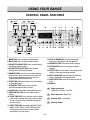
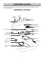
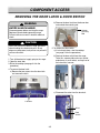
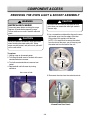
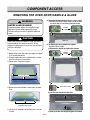
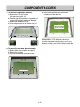
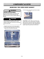
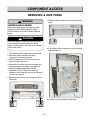
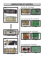
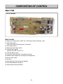
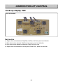
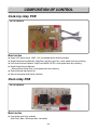
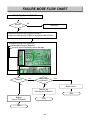
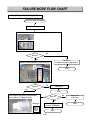
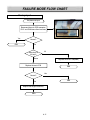
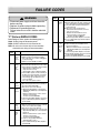
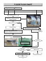
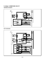
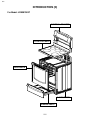
1
Website http://us.lgservice.com
30” Freestanding Electric Range
SERVICE MANUAL
MODEL: LRE30755SW / SB / ST
CAUTION
BEFORE SERVICING THE UNIT, READ THE SAFETY PRECAUTIONS IN THIS MANUAL.
P/NO : 3828W5S6293
December, 2005
Printed in Korea
FORWARD
This LG Service Manual, “ 30” Freestanding Self-Cleaning Electric Range,” provides the
technician with information on the operation and service of the Freestanding Self-Cleaning
Electric Range. It is to be used as a training Service Manual. For specific information on the
model being serviced, refer to the “Owner’s Manual” or “Tech Sheet” provided with the electric
range.
SAFETY PRECAUTIONS
• Repairs of the appliance should be carried out by a licensed technician only. Incorrect repairs
may result in dangerous situations. If you need repairs, contact an LG Service Center or your
dealer.
• If the power cord is defective, it must be replaced by a qualified service agent with a UL listed
range cord.
• Electrical leads and cables should not be allowed to touch the oven.
• Rating plate is located on the left side of warming drawer.
• The power supply of the appliance should be turned off when it is being repaired.
! WARNING
• To avoid risk of severe personal injury or death, disconnect power before working/servicing on
appliance to avoid electrical shock.
• When the oven operates, the interior parts will be very hot.
LG Electronices assumes no responsibility for any repairs made
on our products by anyone other than Authorized Service Technicians.
TABLE OF CONTENTS
(PAGE)
GENERAL- - - - - - - - - - - - - - - - - - - - - - - - - - - - - - - - - - - - - - - - - - - - - - - - - - - - - - - - - - - - - - - - - - - - - - - - - - - - - - - - - - - - - - - - - - - - 1-1 ~ 1-4
• Important safety instructions - - - - - - - - - - - - - - - - - - - - - - - - - - - - - - - - - - - - - - - - - - - - - - - - - - - - - - - - - - - - - - - - - - - - - - - - - - - - - - - - - - - - - - 1-1 ~ 1-2
• Model & Serial number label and tech sheet locations - - - - - - - - - - - - - - - - - - - - - - - - - - - - - - - - - - - - - - - - - - - - - - - - - - - - - - - - - - - 1-3
• Specifications - - - - - - - - - - - - - - - - - - - - - - - - - - - - - - - - - - - - - - - - - - - - - - - - - - - - - - - - - - - - - - - - - - - - - - - - - - - - - - - - - - - - - - - - - - - - - - - - - - - - - - - - - - - - - - - - - - 1-4
USING YOUR RANGE - - - - - - - - - - - - - - - - - - - - - - - - - - - - - - - - - - - - - - - - - - - - - - - - - - - - - - - - - - - - - - - - - - - - - - - - - 2-1 ~ 2-5
• General imformation - - - - - - - - - - - - - - - - - - - - - - - - - - - - - - - - - - - - - - - - - - - - - - - - - - - - - - - - - - - - - - - - - - - - - - - - - - - - - - - - - - - - - - - - - - - - - - - - - - - - - - - - - 2-1
• Control panel features - - - - - - - - - - - - - - - - - - - - - - - - - - - - - - - - - - - - - - - - - - - - - - - - - - - - - - - - - - - - - - - - - - - - - - - - - - - - - - - - - - - - - - - - - - - - - - 2-2 ~ 2-5
- To turn on a single surface unit (Right Rear, Left Rear, Left Front)
- To turn on a dual surface unit (Right Front)
- To set the warming zone controlTo set the warming zone control
- Setting the Clock
- Start, Clean/Off and On/Off pad
- To turn On/Off the oven light
- Timer On/Off
- Options pad: 6 categories
1) Convection auto conversion
2) Thermostat adjustment
3) Language selection (English or Spanish )
4) Preheating alarm light On/Off
5) Beeper volume
6) Temperature unit (°F or °C)
- Bake, Timed Bake, Delayed timed Bake
- Broil
- Convection Bake
- Convection Roast
- Favorites
- Cook & Warm
- Oven lockout
- Changing hour mode on clock (12HR, 24HR)
- Proof
- Self-Clean
- Warming drawer
COMPONENT ACCESS - - - - - - - - - - - - - - - - - - - - - - - - - - - - - - - - - - - - - - - - - - - - - - - - - - - - - - - - - - - - - - - - - - - - - 3-1 ~ 3-17
• Component Locations - - - - - - - - - - - - - - - - - - - - - - - - - - - - - - - - - - - - - - - - - - - - - - - - - - - - - - - - - - - - - - - - - - - - - - - - - - - - - - - - - - - - - - - - - - - - - - - - - - - - - - 3-1
• Removing the Back, Control cover and Key membrane Assembly - - - - - - - - - - - - - - - - - - - - - - - - - - - - - - - - - - - - - - - - - - - 3-2
• Removeing the Control Power Supply and Power Control Board (PCB) - - - - - - - - - - - - - - - - - - - - - - - - - - - - - - - - - - - 3-3
• Removing the Surface Element and the Ceramic Glass Cooktop - - - - - - - - - - - - - - - - - - - - - - - - - - - - - - - - - - - - - - - - - - - 3-4
• Removing the Door Latch and the Door Switch - - - - - - - - - - - - - - - - - - - - - - - - - - - - - - - - - - - - - - - - - - - - - - - - - - - - - - - - - - - - - - - - - - - - - 3-5
• Removing the BROIL element - - - - - - - - - - - - - - - - - - - - - - - - - - - - - - - - - - - - - - - - - - - - - - - - - - - - - - - - - - - - - - - - - - - - - - - - - - - - - - - - - - - - - - - - - - - 3-6
• Removing the BAKE element - - - - - - - - - - - - - - - - - - - - - - - - - - - - - - - - - - - - - - - - - - - - - - - - - - - - - - - - - - - - - - - - - - - - - - - - - - - - - - - - - - - - - - - - - - - - - 3-7
• Removing the CONVECTION element, Fan blade and Fan motor - - - - - - - - - - - - - - - - - - - - - - - - - - - - - - - - - - - - - - - - - - - 3-8
• Removing the Oven light & Socket assembly - - - - - - - - - - - - - - - - - - - - - - - - - - - - - - - - - - - - - - - - - - - - - - - - - - - - - - - - - - - - - - - - - - - - - - - 3-9
• Removing the latch drive assembly - - - - - - - - - - - - - - - - - - - - - - - - - - - - - - - - - - - - - - - - - - - - - - - - - - - - - - - - - - - - - - - - - - - - - - - - - - - - - - - - - - - 3-10
- Door locking mechanism - - - - - - - - - - - - - - - - - - - - - - - - - - - - - - - - - - - - - - - - - - - - - - - - - - - - - - - - - - - - - - - - - - - - - - - - - - - - - - - - - - - - - - - - - - - - - - 3-10
• Removing the Oven temperature Sensor - - - - - - - - - - - - - - - - - - - - - - - - - - - - - - - - - - - - - - - - - - - - - - - - - - - - - - - - - - - - - - - - - - - - - - - - - - - 3-11
• Removing the Warming drawer element & temperature sensor - - - - - - - - - - - - - - - - - - - - - - - - - - - - - - - - - - - - - - - - - - - - - - 3-12
• Removing & Replacing the Lift-off Oven Door - - - - - - - - - - - - - - - - - - - - - - - - - - - - - - - - - - - - - - - - - - - - - - - - - - - - - - - - - - - - - - - - - - - - - 3-13
• Removing the Oven Door Handle & Glass - - - - - - - - - - - - - - - - - - - - - - - - - - - - - - - - - - - - - - - - - - - - - - - - - - - - - - - - - - - - - - - - 3-14 ~ 3-15
• Removing the Oven Door Gasket - - - - - - - - - - - - - - - - - - - - - - - - - - - - - - - - - - - - - - - - - - - - - - - - - - - - - - - - - - - - - - - - - - - - - - - - - - - - - - - - - - - - - 3-16
• Removing a Side Panel - - - - - - - - - - - - - - - - - - - - - - - - - - - - - - - - - - - - - - - - - - - - - - - - - - - - - - - - - - - - - - - - - - - - - - - - - - - - - - - - - - - - - - - - - - - - - - - - - - - 3-17
(Page)
COMPONENT TEST - - - - - - - - - - - - - - - - - - - - - - - - - - - - - - - - - - - - - - - - - - - - - - - - - - - - - - - - - - - - - - - - - - - - - - - - - - - - - 4-1 ~ 4-8
• Convection Motor - - - - - - - - - - - - - - - - - - - - - - - - - - - - - - - - - - - - - - - - - - - - - - - - - - - - - - - - - - - - - - - - - - - - - - - - - - - - - - - - - - - - - - - - - - - - - - - - - - - - - - - - - - • Door locking Motor - - - - - - - - - - - - - - - - - - - - - - - - - - - - - - - - - - - - - - - - - - - - - - - - - - - - - - - - - - - - - - - - - - - - - - - - - - - - - - - - - - - - - - - - - - - - - - - - - - - - - - - - • Micro Switch (normally open type) - - - - - - - - - - - - - - - - - - - - - - - - - - - - - - - - - - - - - - - - - - - - - - - - - - - - - - - - - - - - - - - - - - - - - - - - - - - - - - - - - - • LVT - - - - - - - - - - - - - - - - - - - - - - - - - - - - - - - - - - - - - - - - - - - - - - - - - - - - - - - - - - - - - - - - - - - - - - - - - - - - - - - - - - - - - - - - - - - - - - - - - - - - - - - - - - - - - - - - - - - - - - - - - - - - - - • Oven Sensor - - - - - - - - - - - - - - - - - - - - - - - - - - - - - - - - - - - - - - - - - - - - - - - - - - - - - - - - - - - - - - - - - - - - - - - - - - - - - - - - - - - - - - - - - - - - - - - - - - - - - - - - - - - - - - - - • Warming Drawer Sensor - - - - - - - - - - - - - - - - - - - - - - - - - - - - - - - - - - - - - - - - - - - - - - - - - - - - - - - - - - - - - - - - - - - - - - - - - - - - - - - - - - - - - - - - - - - - - - - • Door switch - - - - - - - - - - - - - - - - - - - - - - - - - - - - - - - - - - - - - - - - - - - - - - - - - - - - - - - - - - - - - - - - - - - - - - - - - - - - - - - - - - - - - - - - - - - - - - - - - - - - - - - - - - - - - - - - - - • Broil element - - - - - - - - - - - - - - - - - - - - - - - - - - - - - - - - - - - - - - - - - - - - - - - - - - - - - - - - - - - - - - - - - - - - - - - - - - - - - - - - - - - - - - - - - - - - - - - - - - - - - - - - - - - - - - - - • Bake element - - - - - - - - - - - - - - - - - - - - - - - - - - - - - - - - - - - - - - - - - - - - - - - - - - - - - - - - - - - - - - - - - - - - - - - - - - - - - - - - - - - - - - - - - - - - - - - - - - - - - - - - - - - - - - - • Convection element - - - - - - - - - - - - - - - - - - - - - - - - - - - - - - - - - - - - - - - - - - - - - - - - - - - - - - - - - - - - - - - - - - - - - - - - - - - - - - - - - - - - - - - - - - - - - - - - - - - - - - • Warming Drawer element - - - - - - - - - - - - - - - - - - - - - - - - - - - - - - - - - - - - - - - - - - - - - - - - - - - - - - - - - - - - - - - - - - - - - - - - - - - - - - - - - - - - - - - - - - - - - - • Oven lamp - - - - - - - - - - - - - - - - - - - - - - - - - - - - - - - - - - - - - - - - - - - - - - - - - - - - - - - - - - - - - - - - - - - - - - - - - - - - - - - - - - - - - - - - - - - - - - - - - - - - - - - - - - - - - - - - - - - • Single surface unit(LF, LR, RR) - - - - - - - - - - - - - - - - - - - - - - - - - - - - - - - - - - - - - - - - - - - - - - - - - - - - - - - - - - - - - - - - - - - - - - - - - - - - - - - - - - - - - • Warming Zone - - - - - - - - - - - - - - - - - - - - - - - - - - - - - - - - - - - - - - - - - - - - - - - - - - - - - - - - - - - - - - - - - - - - - - - - - - - - - - - - - - - - - - - - - - - - - - - - - - - - - - - - - - - - - • Dual surface unit(RF) - - - - - - - - - - - - - - - - - - - - - - - - - - - - - - - - - - - - - - - - - - - - - - - - - - - - - - - - - - - - - - - - - - - - - - - - - - - - - - - - - - - - - - - - - - - - - - - - - - - - -
4-1
4-2
4-2
4-2
4-3
4-3
4-3
4-4
4-4
4-4
4-4
4-5
4-6
4-7
4-8
COMPOSITION OF CONTROL - - - - - - - - - - - - - - - - - - - - - - - - - - - - - - - - - - - - - - - - - - - - - - - - - - - - - - - - - - - - - 5-1 ~ 5-4
• Main PCB - - - - - - - - - - - - - - - - - - - - - - - - - - - - - - - - - - - - - - - - - - - - - - - - - - - - - - - - - - - - - - - - - - - - - - - - - - - - - - - - - - - - - - - - - - - - - - - - - - - - - - - - - - - - - - - - - - - - - - • Cook-top display PCB - - - - - - - - - - - - - - - - - - - - - - - - - - - - - - - - - - - - - - - - - - - - - - - - - - - - - - - - - - - - - - - - - - - - - - - - - - - - - - - - - - - - - - - - - - - - - - - - - - - - - • Cook-top relay PCB - - - - - - - - - - - - - - - - - - - - - - - - - - - - - - - - - - - - - - - - - - - - - - - - - - - - - - - - - - - - - - - - - - - - - - - - - - - - - - - - - - - - - - - - - - - - - - - - - - - - - - - - • Oven relay PCB - - - - - - - - - - - - - - - - - - - - - - - - - - - - - - - - - - - - - - - - - - - - - - - - - - - - - - - - - - - - - - - - - - - - - - - - - - - - - - - - - - - - - - - - - - - - - - - - - - - - - - - - - - - - - - -
5-2
5-3
5-4
5-4
FAILURE MODE FLOW CHART - - - - - - - - - - - - - - - - - - - - - - - - - - - - - - - - - - - - - - - - - - - - - - - - - - - - - - - - - - - - 6-1 ~ 6-11
• No display (No power) - - - - - - - - - - - - - - - - - - - - - - - - - - - - - - - - - - - - - - - - - - - - - - - - - - - - - - - - - - - - - - - - - - - - - - - - - - - - - - - - - - - - - - - - - - - - 6-1 ~ 6-4
• Oven does not heat - - - - - - - - - - - - - - - - - - - - - - - - - - - - - - - - - - - - - - - - - - - - - - - - - - - - - - - - - - - - - - - - - - - - - - - - - - - - - - - - - - - - - - - - - - - - - - - 6-5 ~ 6-7
• Cook-top does not heat - - - - - - - - - - - - - - - - - - - - - - - - - - - - - - - - - - - - - - - - - - - - - - - - - - - - - - - - - - - - - - - - - - - - - - - - - - - - - - - - - - - - - - - - - - 6-8 ~ 6-9
• Oven lamp does not operate - - - - - - - - - - - - - - - - - - - - - - - - - - - - - - - - - - - - - - - - - - - - - - - - - - - - - - - - - - - - - - - - - - - - - - - - - - - - - - - - - - - - - - - - - 6-10
• No key input - - - - - - - - - - - - - - - - - - - - - - - - - - - - - - - - - - - - - - - - - - - - - - - - - - - - - - - - - - - - - - - - - - - - - - - - - - - - - - - - - - - - - - - - - - - - - - - - - - - - - - - - - - - - - - - - 6-11
FAILURE CODES- - - - - - - - - - - - - - - - - - - - - - - - - - - - - - - - - - - - - - - - - - - - - - - - - - - - - - - - - - - - - - - - - - - - - - - - - - - - - - - - - - - - - - - - - - 7-0
F-CODE FLOW CHART - - - - - - - - - - - - - - - - - - - - - - - - - - - - - - - - - - - - - - - - - - - - - - - - - - - - - - - - - - - - - - - - - - - - - 7-1 ~ 7-10
• F-1 error - - - - - - - - - - - - - - - - - - - - - - - - - - - - - - - - - - - - - - - - - - - - - - - - - - - - - - - - - - - - - - - - - - - - - - - - - - - - - - - - - - - - - - - - - - - - - - - - - - - - - - - - - - - - - - - - - - - - - - - - 7-1
• F-2 error - - - - - - - - - - - - - - - - - - - - - - - - - - - - - - - - - - - - - - - - - - - - - - - - - - - - - - - - - - - - - - - - - - - - - - - - - - - - - - - - - - - - - - - - - - - - - - - - - - - - - - - - - - - - - - - 7-2 ~ 7-4
• F-3, F-4 error - - - - - - - - - - - - - - - - - - - - - - - - - - - - - - - - - - - - - - - - - - - - - - - - - - - - - - - - - - - - - - - - - - - - - - - - - - - - - - - - - - - - - - - - - - - - - - - - - - - - - - - - - 7-5 ~ 7-6
• F-5, F-6 error - - - - - - - - - - - - - - - - - - - - - - - - - - - - - - - - - - - - - - - - - - - - - - - - - - - - - - - - - - - - - - - - - - - - - - - - - - - - - - - - - - - - - - - - - - - - - - - - - - - - - - - - - 7-7 ~ 7-8
• F-9 error - - - - - - - - - - - - - - - - - - - - - - - - - - - - - - - - - - - - - - - - - - - - - - - - - - - - - - - - - - - - - - - - - - - - - - - - - - - - - - - - - - - - - - - - - - - - - - - - - - - - - - - - - - - - - 7-9 ~ 7-10
APPENDIX A (SCHEMATIC DIAGRAM OF PCB) - - - - - - - - - - - - - - - - - - - - - - - - - - - - - - - - - - - - - - - - - - - - 8-1
TROUBLE SHOOTING - - - - - - - - - - - - - - - - - - - - - - - - - - - - - - - - - - - - - - - - - - - - - - - - - - - - - - - - - - - - - - - - - - - - - - - - - 9-1 ~ 9-3
SCHEMATIC DIAGRAM - - - - - - - - - - - - - - - - - - - - - - - - - - - - - - - - - - - - - - - - - - - - - - - - - - - - - - - - - - - - - - - - - - - - - - - - - - - - - - - - 10-1
• STRIP CIRCUITS - - - - - - - - - - - - - - - - - - - - - - - - - - - - - - - - - - - - - - - - - - - - - - - - - - - - - - - - - - - - - - - - - - - - - - - - - - - - - - - - - - - - - - - - - - - - - - - - - 10-2 ~ 10-6
EXPLODED VIEW - - - - - - - - - - - - - - - - - - - - - - - - - - - - - - - - - - - - - - - - - - - - - - - - - - - - - - - - - - - - - - - - - - - - - - - - - - - - 11-1 ~ 11-8
GENERAL
IMPOR TANT SAFETY INSTRUCTIONS
Read and follow all instructions before using your oven to prevent the risk of fire, electric shock, injury to person, or
damage when using the range. This guide don’t cover all possible conditions that may occur. For further assistance
contact your service agent or manufacturer.
! WARNING
This symbol will help alert you to hazards or unsafe practices which could cause serious
bodily harm or death.
• Be sure your appliance is properly installed and grounded by a
qualified technician.
! CAUTION
• Do not repair or replace any part of the appliance unless
specifically recommended in the manual.
All other servicing should be referred to a qualified technician.
Do not store items of interest to children in cabinets
above a range or on the back guard of a range – children
climbing on the range to reach items could be seriously
injured.
• Always disconnect power to appliance before servicing by
removing the fuse or switching off the circuit breaker
• Do Not Leave Children Alone - Children should not be left alone or
unattended in area where appliance is in use. They should never be
allowed to sit or stand on any part of the appliance.
! WARNING
– INJURIES CAN OCCUR IF THE
RANGE TIPS
– INSTALL ANTI-TIP DEVICE
PACKED WITH RANGE
– FOLLOW ALL INSTALLATION
INSTRUCTIONS
• Never Use Your Appliance for Warming or Heating the Room.
• Storage in or on Appliance – Flammable materials should not be stored
in an oven or near surface units. Be sure all packing materials are removed
from the appliance before operating it. Keep plastics, clothes and paper
away from parts of the appliance that may become hot
• Wear Proper Apparel – Loose-fitting or hanging garments should never
be worn while using the appliance.
To reduce the risk of tipping of the range, the range must be
secured by properly installed anti-tip devices. To check if the
bracket is installed properly,
• Do Not Use Water on Grease Fires – Turn off oven to avoid spreading
the flame. Smother the fire or flame by closing the door or use dry
chemical, baking soda or foam- type extinguisher.
- Warming drawer : grasp the top rear edge of the Range and
carefully attempt to tilt it forward.
verify that the anti-tip devices are engaged.
• Use Only Dry Potholders – Moist or damp potholders on hot surfaces
may result in burns from steam.
Do not let potholder touch hot heating elements. Do not use a towel or
other bulky cloth.
- Storage drawer : Remove drawer and verify leveling leg is
inserted into and fully secured by the anti-tip devices.
Refer to the installation manual for proper anti-tip bracket
installation.
! WARNING
• Do not step, lean or sit on the doors of the range -this can cause
the range to tip, resulting in burns or serious injuries.
SURFACES
• DO NOT TOUCH SURFACE UNITS OR AREAS NEAR UNITS –
Surface units may be hot even though they are dark in color. Areas
near surface units may become hot enough to cause burns. During
and after use, do not touch, or let clothing or other flammable
materials contact surface units or areas near units until they have
had sufficient time to cool. Among these areas are the cook-top and
surfaces close to the cook-top.
! WARNING
• DO NOT TOUCH HEATING ELEMENTS OR INTERIOR
SURFACES OF OVEN – Heating elements may be hot even
though they are dark in color. Interior surfaces of an oven
become hot enough to cause burns. During and after use, do
not touch, or let clothing or other flammable materials contact
heating elements or interior surfaces of oven until they have
had sufficient time to cool. Other surfaces of the appliance may
become hot enough to cause burns – among these surfaces
are oven vent openings and surfaces near these openings,
oven doors, and windows of oven doors.
! WARNING
To avoid risk of electrical shock, personal injury, or death,
make sure your range has been properly grounded and
always disconnect it from main power supply before any
servicing.
1-1
GENERAL
IMPOR TANT SAFETY INSTRUCTIONS
SURFACE COOKING UNITS
VENTILATING HOODS:
• Use Proper Pan Size – This appliance is equipped with one or
more surface units of different sizes. Select utensils having flat
bottoms large enough to cover the surface unit heating element.
The use of undersized utensils will expose a portion of the heating
element to direct contact and may result in ignition of clothing.
Proper relationship of utensil to burner will also improve efficiency.
• Never Leave Surface Units Unattended at High Heat Settings
– Boil overs may cause smoking and greasy spillovers may ignite.
• Make Sure Reflector Pans or Drip Bowls Are in Place –
Absence of these pans or bowls during cooking may subject
wiring or components underneath to damage.
• Protective Liners – Do not use aluminum foil to line surface unit
drip bowls or oven bottoms, except as suggested in the manual.
Improper installation of these liners may result in a risk of electric
shock, or fire.
• Glazed Cooking Utensils – Only certain types of glass,
glass/ceramic, ceramic, earthenware, or other glazed utensils are
suitable for range-top service without breaking due to the sudden
change in temperature.
• Utensil Handles Should Be Turned Inward and Not Extend
Over Adjacent Surface Units – To reduce the risk of burns,
ignition of flammable materials, and spillage due to unintentional
contact with the utensil, the handle of a utensil should be
positioned so that it is turned inward, and does not extend over
adjacent surface units.
• Do Not Soak Removable Heating Elements – Heating
elements should never be immersed in water.
• Be sure you know which control pads operate each surface unit.
Make sure you turned on the correct surface unit.
• Clean Ventilating Hoods Frequently – Grease should not
be allowed to accumulate on hood or filter.
• When flaming foods under the hood, turn the fan on.
OVEN
• Use Care When Opening Door – Let hot air or steam escape
before you remove or replace food in the oven
• Do Not Heat Unopened Food Containers – Build-up of pressure
may cause container to burst and result in injury.
• Keep Oven Vent Ducts Unobstructed – the oven vent is located
above the left rear surface unit. this area could become hot during
oven use. Never block this vent and never place plastic or heatsensitive items on vent
• Placement of Oven Racks – Always place oven racks in desired
location while oven is cool. If rack must be moved while oven is
hot, do not let potholder contact hot heating element in oven.
• Do Not allow aluminum foil or meat probe to contact heating
elements.
GLASS/CERAMIC COOKING SURFACES
• Do Not Cook on Broken Cook-Top – If cook-top should break,
cleaning solutions and spillovers may penetrate the broken cooktop and create a risk of electric shock. Contact a qualified
technician immediately.
• Clean Cook-Top With Caution – If a wet sponge or cloth is used
to wipe spills on a hot cooking area, be careful to avoid steam
burn. Some cleaners can produce noxious fumes if applied to a hot
surface.
SELF-CLEAN OVENS
• Do Not Clean Door Gasket – The door gasket is essential for a
good seal. Care should be taken not to rub, damage, or move the
gasket.
• Do Not Use Oven Cleaners – No commercial oven cleaner or
oven liner protective coating of any kind should be used in or
around any part of the oven.
• Clean in the self-clean cycle only parts listed in this manual.
Before self-cleaning the oven, remove the broiler pan and any
utensils from the oven.
• Never keep pet birds in the kitchen – the health of birds is
extremely sensitive to the fumes released during an oven selfclean cycle. Fumes may be harmful or fatal to birds. Move birds to
well-ventilated room.
• Important Instruction – In the event the self-clean mode “F”
code goes on, or three long beeps sound, oven is malfunctioning
in the self-clean mode. Turn off or disconnect appliance from
power supply and have serviced by a qualified technician.
DEEP FAT FRYERS:
• Use extreme caution when moving the grease kettle or disposing
of hot grease.
1-2
GENERAL
MODEL & SERIAL NUMBER LABEL
AND TECH SHEET LOCATIONS
The Model/Serial Number label and Tech Sheet locations are shown below.
Model & Serial
Number Location
Tech Sheet Location
(On Low Rear Cover)
1-3
GENERAL
SPECIFICATIONS
Overall
Control
Cooktop
Power
Oven
Drawer
Dimensions
(inch)
Power
Model Number
Category
Width
Installation type
Color availability
Oven
Cooktop
Display
Electronic clock & timer
Control lock capability
Audible preheat signal
Special function
Material
# of element
LR
RR
CR
LF
RF
Capacity(cu.ft)
Broil element
Bake element
Convection System
-Convection element
# of Racks
Interior oven light
Proof
Cook & warm
Favorites
Door lockout
Broiler pan
Type
Element
Warming rack
Oven Interior(W x H x D)
Exterior - Width
Exterior - Height
Exterior - Depth
Net weight: Lbs (Kg)
Rating
LRE30755SW / SB / ST
Convection
30"
Freestanding
WH, BK, STS
Keypad
Keypad
Scroll VFD
Yes
Yes
Yes
Option(6 categories)
1. Convection auto conversion 0n/0ff
2. Thermostat Adjustment
3. Language -English or Spanish
4. Preheating alarm light On/Off
5. Beeper Volume
(loud, normal, low, mute)
6. Temperature unit (F / C)
Ceramic glass
5
6"-1,200
6"-1,200
warming zone
9"-2,500
Dual (9”/12"-1,700/2,700)
5.6
4000 watts
3400 watts
Yes
Yes (800w, 120v)
3 (2 standard, 1 Split)
120V, 40Watts
Yes
Yes
Yes
1. Bread 2. Meat 3. Chicken
Yes
Yes
Warming drawer
600 watts
Yes
24 1/2 x 20 1/4 x 19 3/8
29 7/8
36 (cooktop), 47 5/8 (backguard top)
25 11/16 (Door), 28 (with handle)
181 lbs (82kg)
12.7Kw(120/240V) / 9.7Kw(120/208V)
1-4
USING YOUR RANGE
GENERAL INFORMATION
Rating Label
Convection Bake / Roast Mode
Upper element, lower element, Rear element(some
model) and fan operate during convection bake.
Convection bake should be used for cooking
casseroles and roasting meats. Oven should be
preheated for best results when using convection
bake. Pans do not need to be staggered. Cooks
approximately 25% quicker than bake.
Model numbers are recorded on the rating label.
Rating label is located on the lower front left corner
of the oven frame. It can be seen by opening the
storage drawer or warming drawer. Before ordering
parts, write down the correct model and serial
number from rating label. This avoids incorrect
shipments and delays. Please refer to parts
reference material when ordering replacement parts.
Broil element
Functional Operation
Bake Mode
Top and hidden bottom elements operate during
bake. Bake can be used to cook foods which are
normally baked. Oven must be preheated.
Convection
element
Hidden bake
element
Broil element
Cooking Guide
Refer to the owners manual for recommendations
of times and temperatures. Times, rack position,
and temperatures may vary depending on
conditions and food type. For best results, always
check food at minimum time. When roasting,
choose rack position based on size of food item.
Hidden bake
element
Broil Mode
Top element operates during broil. Broil can be
used to cook foods which are normally broiled.
Preheating is not required when using broil. All
foods should be turned at least once except fish,
which does not need to be turned.
Broil element
Hidden bake
element
2-1
USING YOUR RANGE
CONTROL PANEL FEATURES
A single
A single
C
Left Rear element Warming zone Right Rear element
18
8
A
single
Left Front element
B
9
1 3
10
4 2
11 12 13 14 15 16
5
6
17
D
7
Dual
Right Front
Dual element
1. BAKE PAD: Press to select the bake function.
2. BROIL PAD: Press to select the broil function.
3. CONVECTION BAKE PAD: Press to select baking
with the convection function.
4. CONVECTION ROAST PAD: Press to select
roasting with the convection function.
5. NUMBER PADS: Use to set any function requiring
numbers such as the time of day on the clock, the
timer, the oven temperature, the start time and
length of operation for timed baking.
6. START PAD: Must be pressed to start any cooking
or cleaning function.
7. CLEAR/OFF PAD: Press to cancel all oven
operations except the clock and timer.
8. CLOCK PAD: Press before setting the time of day.
9. TIMER ON/OFF PAD: Press to select the timer
feature.
10. COOK TIME PAD: Press and then use the number
pads to set the amount of time you want your food
to cook. The oven will shut off when the cooking
time has run out.
11. START TIME PAD: Use along with BAKE, CONV.
BAKE, CONV. ROAST, COOK TIME and SELF
CLEAN pads to set the oven to start and stop
automatically at a time you set.
12. COOK & WARM PAD: Press to keep cooked
foods warm. See page 2-4 for pad operation.
13. FAVORITES PAD: Press to set favorite cooking.
14. OPTIONS PAD: Press to set 6 types of option
category.
15. PROOF PAD: Press to select a warm environment
useful for rising yeast-leavened products.
16. SELF CLEAN PAD: Press to select self-cleaning
function. See page 2-4 for pad operation.
17. OVEN LIGHT PAD: Press to turn the oven light on
or off.
18. DISPLAY
2-2
A
Single surface unit
: Right Rear, Left Rear, Left Front
B
Dual surface unit : Right Front
C
Warming Zone : Center Rear
D
Warming Drawer
USING YOUR RANGE
A
To turn on a single surface unit
(Right Rear, Left Rear, Left Front)
4. TIMER ON/OFF
TIMER
ON/OFF
1. Press ON/OFF pad for the desired element.
2. Press ( / ) pad to choose the desired setting.
B
Note:
1. If you press TIMER ON/OFF pad once, this allows you to
select "seconds"
(for example: if you press “5” and “6”, it means 56 seconds)
2. If you press TIMER ON/OFF pad twice, this allows you to
select "minutes"
(for example: if you press “5” and “6”, it means 56 minutes)
5. OPTIONS PAD: 6 types of category
1) CONVECTION AUTO CONVERSION
1. Press OPTIONS pad once
2. Press “1” pad for ENABLE
or “2” pad for DISABLE
3. Press START pad.
2) THERMOSTAT ADJUSTMENT
The oven temperature can be adjusted from
-35°F (-19°C) to 35°F (19°C).
Note:
• Each time a pad is pressed a beep will sound.
• The power level decreases or increases by 0.5
from 9.0 through 3.0. (by 0.2 from 3.0 through 1.0)
• Lo is the lowest power level available.
• “HS” will appear when the unit is hot to touch
To set the warming zone control
1. Press ON/OFF pad at the warming zone.
2. Press ( / ) pad to choose the desired setting.
Note: The thermostat adjustments made with this feature will
just change Bake, Convection Bake and Convection
Roast temperature.
Note:
• Each time a pad is pressed a beep will sound.
• The controls for the warming zone allow for 5
different heat settings : Lo~Hi
• “HS” will appear when the unit is hot to touch.
To increase the oven temperature:
1. Press OPTIONS pad twice
2. Press the desired temperature
3. Press START pad.
To decrease the oven temperature:
1. Press OPTIONS pad twice
2. Press the desired temperature
3. Press the OPTIONS pad once
4. Press START pad
1. SETTING THE CLOCK
CLEAR
/OFF
CLOCK
Desired
Time
TIMER
ON/OFF
To cancel timer at any time, touch TIMER ON/OFF pad.
To turn on a dual surface unit
(Right Front)
1. Press ON/OFF pad
2. Press the ELEMENT SIZE pad as needed to
select the desired burner size. When first
selected, 9” size is on. The light above the
ELEMENT SIZE pad indicates which size
surface unit is on.
2. Press ( / ) pad to choose the desired setting.
C
Desired
time
START
2. START, CLEAN/OFF AND ON/OFF PAD
1. Touch START pad to start oven.
2. Touch CLEAR/OFF pad to cancel a program
during cooking or Erase during programming.
3. Touch ON/OFF pad to start or cancel the
surface unit.
3) LANGUAGE SELECTION (English or
French)
1. Press OPTIONS pad 3 times
2. Press “1” pad for ENGLISH
or “2” pad for FRENCH
3. Press START pad
3. TO TURN ON/OFF THE OVEN LIGHT
The oven light automatically turns ON when the
door is opened. The oven light may also be
manually turned ON or OFF by pressing the
OVEN LIGHT pad
4) PREHEATING ALARM LIGHT ON/OFF
1. Press OPTIONS pad 4 times
2. Press “1” pad for ON
or “2” pad for OFF
3. Press START pad
Note: The oven light cannot be turned on if self-clean feature
is active.
2-3
USING YOUR RANGE
5) BEEPER VOLUME
1. Press OPTIONS pad 5 times
2. Press “1” pad for loud level,
“2” pad for normal level,
“3” pad for low level,
“4” pad for mute level,
3. Press START pad
8. CONVECTION BAKE
CONV.
BAKE
Desired
Temp.
START
9. CONVECTION ROAST
CONV.
ROAST
6) TEMPERATURE UNIT (°F or °C)
1. Press OPTIONS pad 6 times
2. Press “1” pad for °F
or “2” pad for °C
3. Press START pad
Desired
Temp.
START
10. FAVORITES
FAVORITES
: Once → Bread
: Twice → Meat
: 3 times → Chicken
START
6. BAKE, TIMED BAKE, DELAYED TIMED BAKE
BAKE
Desired
temperature
11. COOK & WARM
START
COOK &
WARM
COOK
TIME
Desired time
START
START
12. OVEN LOCKOUT
START
TIME
Desired
start time
Press and hold the START pad for 3 seconds
(to activate or reactivate LOCKOUT)
START
7. BROIL
BROIL: once → Hi
: twice → Low
13. CHANGING HOUR MODE ON CLOCK
(12HR, 24HR)
START
Press and hold the START pad for 3 seconds
Press “1” pad for 12-hour,
“2” pad for 24-hour.
START
14. PROOF
PROOF
START
15. SELF-CLEAN
SELF CLEAN
: Once → 3-hour
: Twice → 2-hour
: 3 times → 4-hour
START
TIME
2-4
Desired
start time
START
START
USING YOUR RANGE
WARMING DRAWER
The rack can be used in 2 ways:
To set the warming drawer control
1. Press the ON/OFF pad at the
WARMING DRAWER
position. The indicator light
will flash.
(If no further pads are
pressed within 25 seconds,
the display will clear.)
2. Press ( ) once to turn on
the power level for high(5
level) or ( ) for Low(1 level).
3. Use the ( )/( ) pad to
choose the desired power
setting.
(Adjustable at any time while
the Drawer is ON.)
4. When the food is ready for
removal, press the ON/OFF
pad once to turn off.
• In the upright position to allow low profile food
items to be placed both under and on top of the
rack (for example, rolls or biscuits on top of the
rack and a casserole dish underneath).
• In the downward position to allow you to place
light weight food items and empty cookware (for
example, rolls or pastries and dinner plates)on the
rack. Set the Warming Drawer rack in either
position as shown below (Fig.1).
Warming Drawer Rack
in upward position
Warming Drawer Rack
in downward position
Note: The Warming Drawer will shut off
automatically after 3 hours.
! CAUTION
Always use pot holders or oven mitts when
removing food from the Warming Drawer as
cookware and plates will be hot and you can be
burned.
To Operate the Warming Drawer
The purpose of the Warming Drawer is
to keep hot cooked foods at serving
temperature. Always start with hot food.
It is not recommended to heat cold food
in the Warming Drawer.
All food placed in the Warming Drawer
should be covered with a lid or
aluminum foil to maintain quality. Do
Warming
not use plastic wrap to cover food.
Plastic may melt onto the drawer and be Drawer
Control
very difficult to clean. Use only utensils
and cookware recommended for oven
use in the Warming Drawer.
2-5
COMPONENT ACCESS
This section instructs you on how to service each component inside the range. The components and their
locations are shown below.
COMPONENT LOCATIONS
Main PCB
Cook Top
Display PCB
Cook Top
Relay PCB
LVT
Door Locking Motor
& Micro Switch
Surface Elements
Door Latch Assembly
Door Switch
Oven Sensor
Oven Light
Convection Motor
Broil Heater
Convection Heater
Thermal Fuse
Bake Heater
Oven Relay PCB
Hinge Hanger
Warming Drawer
Sensor
Warming Drawer
Heater
3-1
COMPONENT ACCESS
REMOVING THE BACK, CONTROL COVER
AND KEY MEMBRANE ASSEMBLY
4. Remove the 3 screws from the rear control cover
and remove the cover.
5. Remove 6 screws of PCB assembly and separate
PCB assembly.
6. Remove 9 screws of KEY Membrane assembly and
separate PCB assembly.
! WARNING
ELECTRICAL SHOCK HAZARD
Disconnect power before servicing the range.
Replace all panels before operating range.
Failure to do so can result in death or electrical
shock.
! CAUTION
When you work on the electric range, be careful
when handling the sheet metal parts. Sharp
edges may be present, and you can cut yourself if
you are not careful.
PCB Assembly
1. Turn off the electrical supply going to the range.
2. Pull the range away from the wall so that you can
access the rear panel.
3. Remove the 16 screws from the rear panel and
remove the panel.
KEY MEMBRANE Assembly
Control Cover
Back Cover
3-2
COMPONENT ACCESS
REMOVING THE CONTROL POWER SUPPLY
AND POWER CONTROL BOARD (PCB)
5. To remove the control power supply:
a) Disconnect 2 connectors.
b) Remove the two screws.
! WARNING
ELECTRICAL SHOCK HAZARD
Disconnect power before servicing the range.
Replace all panels before operating range.
Failure to do so can result in death or electrical
shock.
2 Connector
! CAUTION
When you work on the electric range, be careful
when handling the sheet metal parts. Sharp
edges may be present, and you can cut yourself if
you are not careful.
1. Turn off the electrical supply going to the range.
2. Pull the range away from the wall so that you can
access the rear panel.
3. Remove back cover & control cover (See step
3~4 on page 3-2)
4. There are 3 PCB's (power control board). When
you check PCB, check the proper pcb in default
mode and check main pcb.
NOTE: Refer to the page 5-1~5-4 for
composition of control board
Cook-top Relay PCB
2 Screws
Main PCB
Oven
Relay PCB
3-3
COMPONENT ACCESS
REMOVING THE SURFACE ELEMENTS
AND THE CERAMIC GLASS COOKT OP
Step. 5
Protect the cooktop surface
and turn the assembly over.
! WARNING
ELECTRICAL SHOCK HAZARD
Disconnect power before servicing the range.
Replace all panels before operating range.
Failure to do so can result in death or electrical
shock.
Bracket screws
CERAMIC GLASS COOKTOP REMOVAL
Step. 6
To remove the surface elements
Step. 1
Unplug the cord or disconnect power
a) Remove the wires from
the element and limiter
terminals.
Step. 2
Open oven door and
remove the 3screws located
at the front of the cook-top,
then close the door.
b) Remove the element
bracket screw (shown
above) for the element
you are servicing.
d) Carefully lift the bottom of the bracket just far enough
to remove the element.
3 Screws
Step. 3
Lift up the cooktop front and
Remove the ground screw
securing ground wire
REASSEMBLY NOTE: When you reinstall the element
make sure that the wires are inserted into the correct
tap then reinstall the bracket screw to secure it to the
cooktop.
Ground Screws
Step. 4
Slightly lift up and pull up the
cook-top and then unplug
the 2 connectors at the back
by squeezing side tabs
2 Connectors
3-4
COMPONENT ACCESS
REMOVING THE DOOR LATCH & DOOR SWITCH
b) Remove the door latch from the burner box
and unhook the actuating rod.
! WARNING
ELECTRICAL SHOCK HAZARD
Unhook
Actuating
Rod
Disconnect power before servicing the range.
Replace all panels before operating range.
Failure to do so can result in death or electrical
shock.
! CAUTION
When you work on the electric range, be careful
when handling the sheet metal parts. Sharp
edges may be present, and you can cut yourself if
you are not careful.
5. To remove the door switch:
a) If not already done, raise the cooktop
(see page 3-4 for the procedure).
b) Remove the door switch from the range.
To do this, squeeze tabs and use a ratchet
extension or a small socket, and tap it out of
the hole with a hammer.
1. Turn off the electrical supply going to the range.
2. Open the oven door.
3. Raise the cooktop (see page 3-4 for the
procedure).
4. To remove the door latch:
a) Remove the two screws from the door latch
and remove the latch.
c) Disconnect the wires from the terminals.
2 Screws
Wires
Door
Switch
3-5
COMPONENT ACCESS
REMOVING THE BROIL ELEMENT
b) Pull the element forward so that you can
access the terminals and disconnect the wires.
! WARNING
ELECTRICAL SHOCK HAZARD
2 Terminals
Disconnect power before servicing the range.
Replace all panels before operating range.
Failure to do so can result in death or electrical
shock.
! CAUTION
When you work on the electric range, be careful
when handling the sheet metal parts. Sharp
edges may be present, and you can cut yourself if
you are not careful.
1. Turn off the electrical supply going to the range.
2. Open the oven door and remove the racks from
inside the oven.
3. To remove the broil element:
a) Remove the 4 screws from the front and rear
brackets.
2 Upper bracket Screws
2 Rear bracket Screws
3-6
COMPONENT ACCESS
REMOVING THE HIDDEN BAKE ELEMENT
1. Unplug range or disconnect power.
2. Pull the range out of its mounting location so that
you can access the rear of the unit.
3. Remove the rear panel from the unit.
(See step 3 on page 3-2 for procedure)
7. Bend the insulation glass fiber up.
Hidden
bake
element
Hidden
bake
element
Hiddenbake
bakeelement
element
Hidden
Hidden
bake
element
Hidden
bake
element
8. Remove two screws
and bend up two flanges
Screw
Screw
Screw
Screw
Screw
Screw
Screw
Flanges
9. Carefully pull the hidden bake element and its
mounting bracket out of the range.
4. Remove the 2 screws of
power cord assembly
box and 1 ground screw.
5. Set the box aside
6. Cut the 9 points of flange and remove the bake
heater cover.
REPLACING THE MOUNTING BRACKET
Total
points
Total
points
Total
99
points
Total9
points
Total
Total
99points
points
Total
99
points
1. Drive the two screws
3-7
COMPONENT ACCESS
REMOVING THE CONVECTION ELEMENT, FAN BLADE AND FAN MOTOR
1. Disconnect power and remove oven racks.
2. Pull the range out of its mounting location so that
you can access the rear of the unit.
3. Remove the rear panel from the unit.
(See step 3~4 on page 3-2 for procedure)
4. Disconnect the wire connection.
8. To remove Fan motor assembly, disconnect
wire connection and remove the three bracket
screws
9. Pull the fan motor assembly forward.
Fan cover
Convection
heater
Fan
blade Support
Fan motor
Washer
5. Remove the four Fan cover screws and set the
fan cover aside.
Mounting
Screws
(3ea)
Fan cover
Screws
(4ea)
Cavity
Inner
Outer
Nut
6. Remove the two convection
element screws and pull the
element forward.
Nut
Nut
Nut
Nut
Nut
Nut
Nut
7. To remove Fan blade, remove Nut by screwing
clockwise. Fan blade can be replaced from inside
oven.
! CAUTION
Be careful not to bend the fan blade.
3-8
COMPONENT ACCESS
REMOVING THE OVEN LIGHT & SOCKET ASSEMBLY
! CAUTION
! WARNING
Be careful not to scratch or chip the oven liner
paint when you remove the oven light socket in
the next step.
ELECTRICAL SHOCK HAZARD
Disconnect power before servicing the range.
Replace all panels before operating range.
Failure to do so can result in death or electrical
shock.
5. Use a screwdriver and bend the clips on the oven
light socket away from the edges of the liner
hole, and pull the socket out of the liner.
NOTE: If it is too difficult to remove the socket
from the front of the oven, you will have to push
the socket out from the back of the unit.
! CAUTION
When you work on the electric range, be careful
when handling the sheet metal parts. Sharp
edges may be present, and you can cut yourself if
you are not careful.
To replace:
1. Unplug range or disconnect power.
2. Turn the glass bulb cover in the back of the oven
counterclockwise to remove.
3. Turn bulb counterclockwise to remove from
socket.
4. Replace bulb and bulb cover by turning
clockwise.
Socket
Clips
Socket
Clips
Socket
SocketClips
Clips
Socket
Clips
Socket
Clips
Socket
Clips
Glass cover & Bulb
5. Disconnect the wires from the socket terminals.
<Viewed From Rear Panel>
3-9
COMPONENT ACCESS
REMOVING THE LATCH DRIVE ASSEMBLY
DOOR LOCKING MECHANISM
! WARNING
The door lock assembly is located at the back side
of range.
The structural elements are as below.
ELECTRICAL SHOCK HAZARD
Disconnect power before servicing the range.
Replace all panels before operating range.
Failure to do so can result in death or electrical
shock.
1. When the oven control is programmed and started for
the Self clean and Lock out mode, PCB (Power control
board) chip operates the motor.
! CAUTION
When you work on the electric range, be careful
when handling the sheet metal parts. Sharp
edges may be present, and you can cut yourself if
you are not careful.
HOOK
Latch ROD
1. Turn off the electrical supply going to the range.
2. Pull the range away from the wall so that you can
access the rear panel.
3. Remove the back cover & control cover (see step
3~4 on page 3-2).
4. Disconnect the wires from the latch drive motor
and switch.
5. Remove the two mounting screws from the latch
drive.
screws
CAM
MICRO
SWITCH
MOTOR
screws
2. The cam moves the door hook connected to latch rod
from unlocked position to locked position (from locked
Position to unlocked position)
3. The cam activates the micro switch that causes the
motor to stop.
4. The locked status remains until the range temperature
drops to approximately 500F after end of the self clean
or lock out feature is reactivated. The motor operates to
unlock door at that time.
6. Unhook the Latch rod from the cam.
3-10
COMPONENT ACCESS
REMOVING THE OVEN TEMPERATURE SENSORS
5. To remove an oven temperature sensor,
disconnect the connector from the main harness
and remove the two mounting screws in oven
cavity.
! WARNING
ELECTRICAL SHOCK HAZARD
Disconnect power before servicing the range.
Replace all panels before operating range.
Failure to do so can result in death or electrical
shock.
Screws
! CAUTION
When you work on the electric range, be careful
when handling the sheet metal parts. Sharp
edges may be present, and you can cut yourself if
you are not careful.
Main oven Sensor
1. Turn off the electrical supply going to the range.
2. Open the oven door and remove the racks from
the oven.
3. Pull the range away from the wall so that you can
access the rear panel.
4. Remove the 16 screws from the rear panel and
remove the panel (see step 3 on page 3-2).
Main
oven
Sensor
Main
oven
Sensor
Mainoven
ovenSensor
Sensor
Main
Main
Main
oven
oven
Sensor
Sensor
connector
connector
connector
connector
connector
connector
3-11
COMPONENT ACCESS
REMOVING THE WARMING DRAWER ELEMENT
& TEMPERATURE SENSOR
To remove the warming drawer element:
1. Remove the two bottom bracket screws
! WARNING
ELECTRICAL SHOCK HAZARD
Disconnect power before servicing the range.
Replace all panels before operating range.
Failure to do so can result in death or electrical
shock.
rear
bracket
screws
rear
rear
bracket
bracket
screws
screws
22
2rear
rearbracket
bracketscrews
screws
22
rear
bracket
screws
22
rear
bracket
screws
! CAUTION
bottom
bracket
screws
bottom
bracket
screws
2bottom
bottombracket
bracketscrews
screws
22
bottom
bracket
screws
22
bottom
bracket
screws
22
bottom
bracket
screws
2. Remove the two rear bracket screws, and
disconnect the wires from the terminals.
When you work on the electric range, be careful
when handling the sheet metal parts. Sharp
edges may be present, and you can cut yourself if
you are not careful.
To remove the warming drawer temperature
sensor:
1. Unplug the cord or disconnect power.
2. Pull the range away from the wall so that you can
access the back cover.
3. Remove the back cover.
4. Remove the sensor cover screw and remove
sensor cover.
To Remove Warming Drawer:
1. CAUTION - Turn power OFF before removing
the Warming Drawer.
2. Open the drawer to the fully opened position.
3. Remove the 2 screws (right and left side). (refer
to below picture)
4. Locate glide lever
Remove screw
on each side of
drawer, push
down on the left
glide lever and pull up on the right glide lever.
Lever
Lever
Sensor cover screw
Push down with finger
Push up with finger
5. Remove the rear bracket screws (2ea).
5. Pull the warming drawer away from the range.
Rear
bracket
screws
Rear
bracket
screws
Rear
Rear
Rearbracket
bracket
bracketscrews
screws
screws
Rear
bracket
screws
6. Pull the sensor forward and unplug the
connectors.
3-12
COMPONENT ACCESS
REMOVING & REPLACING THE LIFT-OFF OVEN DOOR
To replace the door:
! CAUTION
Step. 1
The door is very heavy. Be careful when
removing and lifting the door. Do not lift the door
by the handle.
Firmly grasp both
sides of the door
at the top.
To remove the door:
Hinge arm
Step. 2
Step. 1
Fully open the door.
With the door at
Bottom
the same angle as
edge of
the removal
slot
position, seat the
Indentation
indentation of the
hinge arm into the
bottom edge of the hinge slot. The notch in the hinge
arm must be fully seated into the bottom of the slot.
Lock
Unlock
Slot
Step. 2
Pull the hinge locks down Hinge
lock
toward (Fig.1) the door
frame, to the unlocked
position.
<Fig.1>
Step. 3
Step. 3
Fully open the door. If the door will not fully open, the
indentation is not seated correctly in the bottom edge
of the slot.
Firmly grasp both sides of the door at the top.
Step. 4
Step. 4
Close door to the door removal
position, which is approximately
5 degrees. (refer to the Fig.2)
Step. 5
Push the hinge locks up
against the front frame of the
oven cavity to the locked
position.
<Fig.2>
Lift door up and out until the hinge arm is clear of the
slot.
Step. 5
Close the oven door.
3-13
Hinge arm
Hinge lock
COMPONENT ACCESS
REMOVING THE OVEN DOOR HANDLE & GLASS
6. To remove the door handle & trim (for stainless model)
a) Remove the 4 door handle screws and lift the door
handle off door trim and slide up the door handle.
! WARNING
ELECTRICAL SHOCK HAZARD
Disconnect power before servicing the range.
Replace all panels before operating range.
Failure to do so can result in death or electrical
shock.
Handle
screws
! CAUTION
Door trim
When you work on the electric range, be careful
when handling the sheet metal parts. Sharp
edges may be present, and you can cut yourself if
you are not careful.
6. To remove the door handle trim & glass
(for white / Black model)
a) Remove the handle and glass trim screws
Handle
screws
1. Remove the oven door from the range (see page
3-13 for the procedure).
2. Place the oven door on a padded work surface
with the front glass facing down.
3. Remove the 4 top door screws.
top
liner
screws
4444top
top
liner
screws
topliner
linerscrews
screws
44
top
top
liner
liner
screws
screws
Glass trim screws
4. Remove the three bottom screws from the door
liner.
b) Lift the door handle off door trim
3 bottom liner screws
5. Lift the liner assembly off the front glass and set
it aside.
c) Slide up the door trim and pull the glass trim forward
3-14
COMPONENT ACCESS
7. To remove a hinge hanger assembly:
a) Remove the 2 top liner screws
(See step 3 on page 3-14)
b) Place the door liner assembly on a padded work
surface with the hinge hangers over the edge.
c) Remove the two bottom screws.
d) Lift the hinge hanger out of the door liner slot.
d) Lift the inner oven door glass and bracket
assembly out of the door liner.
lnner
Oven
Door
lnner
Oven
Door
lnnerOven
OvenDoor
Door
lnner
lnner
Oven
Door
lnner
Oven
Door
lnner
Oven
Door
Glass
&
Bracket
Glass
&
Bracket
Glass
&
Bracket
Glass
&
Bracket
Glass
&
Bracket
Glass
Glass &
& Bracket
Bracket
Hinge
hanger
screws
Hinge
hanger
screws
Hinge
hanger
screws
Hinge
Hingehanger
hangerscrews
screws
Hinge
hanger
screws
Hinge
hanger
screws
REASSEMBLY NOTE: When you reinstall the
insulation around the oven door glass, make sure
that the insulation is not visible in the glass after the
door is reassembled.
8. To remove the oven door glass assembly:
a) Remove both hinge hangers (see step 8).
b) Remove the 6 screws.
c) Lift the insulation cover off the door liner.
lnsulation
cover
lnsulation
cover
lnsulationcover
cover
lnsulation
lnsulation
lnsulation
cover
cover
lnsulation
cover
3-15
COMPONENT ACCESS
REMOVING THE OVEN DOOR GASKET
3. Pull the ends of the gasket out of the liner holes.
! WARNING
Liner Hole
ELECTRICAL SHOCK HAZARD
Disconnect power before servicing the range.
Replace all panels before operating range.
Failure to do so can result in death or electrical
shock.
! CAUTION
When you work on the electric range, be careful
when handling the sheet metal parts. Sharp
edges may be present, and you can cut yourself if
you are not careful.
REASSEMBLY NOTE: When you install the new
gasket, make sure that all of the clips are seated in
their liner holes, and that the ends of the gasket are
pushed fully into their holes. Use the pointed end of
a pencil to push the gasket ends into the holes.
1. Open the oven door to its fully down position.
2. Pull the oven door gasket clips out of the liner
holes until all of the clips are removed.
Door
gasket
Door
gasket
Door
Doorgasket
gasket
Door
gasket
Door
gasket
Door
gasket
Gasket
clip
Gasket
clip
Gasketclip
clip
Gasket
Gasket
clip
Gasket
clip
Gasket
clip
3-16
COMPONENT ACCESS
REMOVING A SIDE PANEL
7. Remove the two screws from the left or right side
panel.
! WARNING
ELECTRICAL SHOCK HAZARD
Disconnect power before servicing the range.
Replace all panels before operating range.
Failure to do so can result in death or electrical
shock.
! CAUTION
When you work on the electric range, be careful
when handling the sheet metal parts. Sharp
edges may be present, and you can cut yourself if
you are not careful.
8. Pull the back of the side panel out from the range
approximately 10˚.
1. Turn off the electrical supply going to the range.
2. Remove the oven door from the range
(see page 3-13 for the procedure).
3. Pull the range away from the wall so you can
access the back of the unit.
4. Remove the 16 screws from the rear panel and
remove the panel (see step 3~4 on page 3-2).
5. Raise the cooktop (see page 3-4 for the
procedure). NOTE: Position the side of the
cooktop so that it does not rest on the side panel
that you are removing.
6. Remove the two screws from the top rear of the
side panel.
9. Push forward and remove the side panel.
3-17
COMPONENT TEST
Before testing any of components, perform the following checks:
NOTE:
1. The most common cause for control failure is corrosion on connectors.
Therefore, disconnecting and reconnecting wires will be necessary throughout test procedures
2. ALL units in the first few days of use should be checked for mis-wiring or loose connections
1. All/tests/checks should be made with a VOM or DVM having a sensitivity of 20,000 ohms per-volt DC, or
greater.
2. Check all connections before replacing components, looking for broken or loose wires, Failed terminals, or
wires not pressed into connectors far enough.
3. Resistance checks must be made with power cord unplugged from outlet, and with wiring harness or
connectors disconnected.
! WARNING
• Disconnect power supply cord from the outlet before servicing
• Replace all panels and parts before operating
• Reconnect all grounding devices after servicing
Failure to do so can result in death or electrical shock
NOTE: Below Ω value were tested at room temperature (77F/25°C)
Components
Convection Motor
Test procedures
1. Refer to page 3-8 for the servicing procedure
2. Measure the resistance
(Multiple meter scale: R x 1)
4-1
Results
Normal: Approximately
33.5 Ω ± 10%
If not replace
Abnormal: Infinite (open)
below 5Ω (shorted)
Components
Test procedures
Door locking Motor
1. Refer to page 3-10 for the servicing procedure
2. Measure the resistance
(Multiple meter scale: R x 1000)
Micro Switch
(normally open type)
1. Refer to page 3-10 for the servicing procedure
2. Measure the resistance
(Multiple meter scale: R x 1000)
Results
Normal: Approximately
2.6 kΩ ± 10%
If not replace
Abnormal: Infinite(open)
below 5Ω (shorted)
Door latch
open
Door latch
Locked
Continuity
Infinite
NO
COM
NOTE: After checking for the continuity of switch, make sure that they are
connected correctly
LVT
1. Refer to page 3-3 for the servicing procedure
2. Measure the resistance
(Multiple meter scale: R x 1000)
4-2
Normal: Approximately
27 Ω ± 10%
If not replace
Components
Oven Sensor
Test procedures
1. Refer to page 3-11 for the servicing procedure
2. Measure the resistance after cooling down
(Multiple meter scale: R x 1000)
Results
Normal: Approximately
1.09 kΩ ± 10%
If not replace
NOTE: Ω Value was tested
at room temperature
(77F/25˚C)
NOTE: Oven sensor is so sensitive to temperature
Do test after cooling down sufficiently
Warming Drawer Sensor
1. Refer to page 3-12 for the servicing procedure
2. Measure the resistance after cooling down
(Multiple meter scale: R x 1000)
Normal: Approximately
4.6 kΩ ± 10%
If not replace
NOTE: Ω Value was tested
at room temperature
(77F/25˚C)
NOTE: Oven sensor is so sensitive to temperature
Do test after cooling down sufficiently
Door switch
1. Refer to page 3-5 for the servicing procedure
2. Measure the resistance after cooling down
(Multiple meter scale: R x 1000)
4-3
Door open
Door closed
Continuity
Infinite
Components
Broil element
Test procedures
1. Refer to page 3-6 for the servicing procedure
2. Measure the resistance after cooling down
(Multiple meter scale: R x1)
Results
Normal: Approximately
14 Ω ± 10%
If not replace
NOTE: Ω Value was tested
at room temperature
(77F/25˚C)
Be careful the element is
sensitive to temperature.
Bake element
1. Refer to page 3-7 for the servicing procedure
2. Measure the resistance after cooling down
(Multiple meter scale: R x1)
Normal: Approximately
17 Ω ± 10%
If not replace
NOTE: Ω Value was tested
at room temperature
(77F/25˚C)
Be careful the element is
sensitive to temperature.
Convection element
1. Refer to page 3-8 for the servicing procedure
2. Measure the resistance after cooling down
(Multiple meter scale: R x1)
Normal: Approximately
17 Ω ± 10%
If not replace
NOTE: Ω Value was tested
at room temperature
(77F/25˚C)
Be careful the element is
sensitive to temperature.
Warming Drawer element
1. Refer to page 3-12 for the servicing procedure
2. Measure the resistance after cooling down
(Multiple meter scale: R x1)
Normal: Approximately
95 Ω ± 10%
If not replace
NOTE: Ω Value was tested
at room temperature
(77F/25˚C)
Be careful the element is
sensitive to temperature.
4-4
Components
Oven lamp
Test procedures
1. Measure the resistance after cooling down
(Multiple meter scale: R x1)
4-5
Results
Normal: Below 5 Ω.
If not replace
Components
Single surface units:
Left Front (LF),
Left Rear (LR)
and
Right Rear(RR)
Element
Test procedures
Results
1. Refer to page 3-4 for the servicing procedure
2. Set the Multiple meter scale to the R x 1
3. Disconnect wires from cook-top elements
4. Touch the ohmmeter test leads to the element
terminal and 1A.
The meter should indicate 46 Ω ± 10%
Element
terminal
1A
Normal: Approximately 46 Ω,
If not replace
5. Touch the ohmmeter test leads to limiter
terminals 1A and 2A. The meter should indicate
continuity.(0Ω)
2A
Normal: continuity
(below 0.5 Ω)
If not replace
1A
6. Touch the ohmmeter test leads to limiter
terminals 1B and 2B.
With the temperature below 150˚F, the meter
should indicate an open circuit(infinite).
With the temperature above 150˚F, the meter
should indicate continuity (0Ω).
2B
1B
4-6
Below 150˚F
open circuit(infinite).
Above 150˚F
continuity (0 Ω)
Components
Center Rear(CR)
Element
;Warming Zone
Test procedures
Results
1. Refer to page 3-4 for the servicing procedure
2. Set the Multiple meter scale to the R x 1
3. Disconnect wires from CR elements
4. Touch the ohmmeter test leads to the element
terminal and 1A. The meter should indicate
565 Ω ± 10%
Element
terminal
Normal: Approximately 565 Ω,
If not replace
1A
5. Touch the ohmmeter test leads to limiter
terminals 1A and 2A.the meter should indicate
continuity (0 Ω)
2A
Normal: continuity
(below 0.5 Ω)
If not replace
1A
6. Touch the ohmmeter test leads to limiter
terminals 1B and 2B.
With the temperature below 150˚F, the meter
should indicate an open circuit(infinite).
With the temperature above 150˚F, the meter
should indicate continuity (0 Ω).
2B
1B
4-7
Below 150˚F
open circuit(infinite).
Above 150˚F
continuity (0 Ω)
Components
Dual surface element
: Right Front(RF)
Test procedures
Results
1. Refer to page 3-4 for the servicing procedure
2. Set the Multiple meter scale to the R x1
3. Disconnect wires from cook-top elements
4. Touch the ohmmeter test leads to the (E1 & 1A)
and (E2 & 1A) the meter should indicate :
32 Ω ± 10%
- (E1 & 1A)
- (E2 & 1A)
55 Ω ± 10%
E1 E2
Normal: Approximately 32 Ω
1A
Normal: Approximately 55 Ω
5. Touch the ohmmeter test leads to limiter
terminals 1A and 2A.the meter should indicate
continuity (0 Ω)
2A
1A
6. Touch the ohmmeter test leads to limiter
terminals 1B and 2B.
With the temperature below 150˚F, the meter
should indicate an open circuit(infinite).
With the temperature above 150˚F, the meter
should indicate continuity (0 Ω).
2B
Normal: continuity
(below 0.5 Ω)
If not replace
1B
4-8
Below 150˚F
open circuit(infinite).
Above 150˚F
continuity (0 Ω)
COMPOSITION OF CONTROL
Main PCB ( P/N : 6871W1N009A)
Front
Front
Back
Back
Cook top display PCB ( P/N : 6871W1N010A)
Controller assembly
Front
Back
Cook top relay PCB ( P/N : 6871W1N011A)
Key pad assembly
Front
Front
Back
Oven relay PCB ( P/N : 6871W1N012A)
Back
Front
PCB case assembly
5-1
Back
COMPOSITION OF CONTROL
Main PCB
P/N : 6871W1N009A
Main function
▶ Supply a DC power source (GND, -5V, -12V(Vry(oven heater switching)), -30V)
▶ Oven heater control
(DLB / Broil / Bake / Warming drawer / convection)
▶ Oven display control
▶ Warming drawer display control
▶ Cook top heater control
(Warmer zone / RR / LR / RF / LF)
▶
▶
▶
▶
▶
▶
▶
▶
Cook top display control
Oven lamp / door lock motor / convection fan control
Detecting oven temperature / warming drawer temperature
Buzzer sound control
Key entry
Door open/close, Door lock/unlock detection
Error mode detection and pop up
Supervising hot cook top element
5-2
COMPOSITION OF CONTROL
Cook-top display PCB
P/N : 6871W1N010A
Main function
▶
▶
▶
▶
Single radiant surface elements -Right Rear, Left Rear, Left Front- power level indication
Dual radiant surface elements -Right Front inner, outer- power level indication
Dual radiant surface element size indication -Right Front inner, outer
Single radiant surface elements -warming zone (Center Rear) - power level indication
5-3
COMPOSITION OF CONTROL
Cook-top relay PCB
P/N : 6871W1N011A
Main function
▶
▶
▶
▶
Supply a DC power source (GND, -12V (Vry(cooktop heater switching voltage))
Single Radiant Surface Elements -Right Rear, Left Rear, Left Front - on/off, power level relay switching
Dual Radiant Surface Elements -Right Front INNER, OUTER - on/off, power level relay switching
Single Radiant Surface Elements
- Warming Zone (Center Rear) -on/off, power level relay switching
▶ Supervising cook top element hot
▶ Warm drawer power level(5 level) indication
Oven relay PCB
P/N : 6871W1N012A
Main function
▶ Oven heater on/off relay switching
(DLB / Broil / Bake / Warming drawer / convection)
5-4
CHECKING FLOW CHART BY FAILURE MODE
No display (No power)
Blank display
Enter key input
Some beep
sound?
No
Check the thermal fuse
(See the page 3-1)
No
Check AC input voltage of Main PCB
-Main PCB CN2 (pin 1 and 3)
Yes
Cook-top display
blank?
1
(Go to page 6-4)
Yes
Check voltage – Main PCB(009A) CN14 (Pin 10 and 12)
CN14(Pin 10 and 12)
The voltage should be
(-)4.5V ~ (-)5.5V
Main PCB(009B)
(-)4.5V ~ (-)5.5V ?
No
Yes
Replace the main PCB(009A)
Replace the cook-top display PCB(010A)
END
END
6-1
FAILURE MODE FLOW CHART
No display (No power)
Blank display
Enter key input
Some beep
sound?
No
Check the thermal fuse
(See the page 3-1)
No
Check AC input voltage of Main PCB
-Main PCB CN2 (pin 1 and 3)
Yes
Warming drawer
display blank?
1
(Go to page 6-4)
Yes
Check voltage – Main PCB(009B) CN16 (Pin 11) and CN9(Pin1)
CN16(Pin11)
Voltage should be
(-)4.5V ~ (-)5.5V
CN9(Pin1)
Main PCB(009B)
(-)4.5V ~ (-)5.5V ?
Yes
No
Replace the main PCB(009A)
Replace the warming drawer
display PCB(011A)
END
6-2
END
FAILURE MODE FLOW CHART
No display (No power)
Blank display
Enter key input
Some beep
sound?
No
Check the thermal fuse
(See the page 3-1)
Yes
Oven display
blank?
No
Check AC input voltage of Main PCB
-Main PCB CN2 (pin 1 and 3)
1
(Go to page 6-4)
Yes
Replace the main PCB(009A)
END
6-3
FAILURE MODE FLOW CHART
No display (No power)
1
Check the harness of between L1~N
No
Is it 120V AC?
Yes
Normal?
Yes
No
Disconnect power
Replace the defective harness
Check the power transformer (Refer to the below)
Primary
S3 S2 S1
Fig.1
Side
P
S1
S2
S3
P
Secondary
Lead Color
black ~ white
yellow ~ blue ~ yellow
green ~ green
red ~ red
DCR(Ω)
25 ~ 28
4.2 ~ 4.9
1.5 ~ 1.8
1.1 ~ 1.3
measure LVT coil resistance
(Normal: approximately Fig.1)
No
Normal?
Yes
Replace the power transformer
Replace the Main PCB(009A)
END
END
6-4
FAILURE MODE FLOW CHART
Oven does not heat
Code
F-7
Error mode
Operation
No heating
Times/sampling
If current oven temperature does not exceed 150˚F and
less than start temperature over 5 minutes on preheating,
where door is closed. (except proof and cook & warm )
During cook
No Heating(Main Oven)
Disconnect power
Check for loose connections at bake, broil,
convection heater terminal and harness
Normal?
No
Yes
Reconnect.
If defective harness,replace or fix
Check the bake heater
(measure the resistance after cooling down)
Normal: approximately 17Ω
END
Continued on the next page
6-5
FAILURE MODE FLOW CHART
Oven does not heat
Normal?
No
Yes
Replace the bake heater
Check the broil heater
(measure the resistance after cooling down)
Normal: approximately 14Ω
END
Normal?
No
Yes
Replace the broil heater
Check the convection heater
(measure the resistance after cooling down)
Normal: approximately 17Ω
END
Normal?
No
Yes
Replace the convection heater
Continued on the next page
END
6-6
FAILURE MODE FLOW CHART
Oven does not heat
Check for loose oven sensor connector
Normal?
No
Yes
Reconnect
Check the oven sensor
(measure the resistance after cooling down)
Normal: approximately 1.09kΩ
Normal?
END
No
Yes
Replace the oven sensor
Replace the oven relay PCB (012A)
END
Normal?
Yes
Replace the main PCB(009A)
For further check of main PCB
Refer to the appendix A
END
6-7
FAILURE MODE FLOW CHART
Cook-top does not heat
No heating
(All or a part of cook-top heaters)
Disconnect power
Check for loose connection at board (011B PCB)
to cook top heaters.
Normal?
No
Yes
Reconnect.
If defective harness, replace or fix
Check for loose connector
(main PCB(009A) CN9 and CN16)
END
Continued on the next page
6-8
FAILURE MODE FLOW CHART
Cook-top does not heat
No
Normal?
Reconnect.
Yes
Remove the cook-top relay PCB(011A) harness
and pull the cook-top relay PCB(011A) forward from the PCB case
Inspect the cook-top relay PCB(011A)
Wide pattern(Live part) blown out
pin to pin short or connector harness damaged
Normal?
Yes
No
Repairable
by yourself?
No
Replace the
Cook-top relay PCB(011A)
Replace
the main PCB(009A)
END
END
6-9
Yes
Repair and fix
END
FAILURE MODE FLOW CHART
Oven lamp does not operate
Oven lamp does not operate
Disconnect power
Check for loose connection of oven lamp terminal and harness
Normal?
No
Yes
Reconnect
If defective harness, replace or fix
Check for loose connector (main PCB CN1)
END
Normal?
No
Reconnect
Yes
END
Check the oven lamp (measure the resistance)
Normal: Below 5 Ω , Abnormal: infinite
Normal?
No
Replace the
oven lamp
Yes
Abnormal
Replace
the main PCB(009A)
Infinite
END
6-10
END
FAILURE MODE FLOW CHART
No key input
Key does not input
Reconnect the main PCB connector
CN11 and CN20 more than two times
Yes
END
Normal?
No
All
Some keys or
All keys?
Some
Replace the main PCB(009A)
Replace the main PCB
END
Yes
Normal?
END
No
Replace the keypad assembly
END
6-11
FAILURE CODES
DISPLAY CAUSE
SHOWS
! WARNING
F7
• Disconnect power supply cord from the outlet
before servicing
• Replace all panels and parts before operating.
• Reconnect all grounding devices
Failure to do so can result in death or electrical
shock
“F” (Failure) DISPLAY CODES
Before doing any action, perform the following step1~3.
Step1. Unplug range or disconnect power.
Step2. Check if connector is fully seated or not.
Note: All units in the first few days of use should be
checked for mis-wiring or loose connections.
DISPLAY CAUSE
SHOWS
F1
F2
F3
F4
F5
F6
F9
CORRECTIVE ACTION
Key held
down too
long or
shorted
key
Door
Locking
system
don’t
operate
A. Perform step 1 through 2 above
B. Replace keypad or keypad assembly
(if F code recur, go to C after unplugging
or disconnecting)
C. Replace Control (PCB) assembly
A. Perform step 1 through 2 above
B. Check wire and connections from control to latch
C. If motor operate, check integrity of latch mechanism
- check the micro-switch (refer to
component test section)
- check integrity of door locking mechanism
D. If motor didn’t operate, check continuity of
the latch motor and electrical connections
- if the wiring is bad, replace the harness
- if the wiring is good, replace the door
motor assembly
- if F code recur, replace control
Main oven A. Perform step 1 through 2 above
Sensor
B. Open the back panel and check continuity of
opened
the sensor and Control (PCB)
Main oven C. Disconnect sensor from harness
D. - Measure Ω value between connector pins :
Sensor
Approximately 1090 Ω (at room temperature:
shorted
77F/25°C)
- Measure value between sensor chassis
and any connector pins
: Ω value should read OPEN
=> if there is any problem, Replace oven sensor
E. If you couldn’t find any problem, Replace
Control (PCB)
Warming A. Perform step 1 through 2 above
B. Open the back panel and check continuity
drawer
of the sensor and Control (PCB)
Sensor
C. Disconnect sensor from harness
shorted
D.- Measure Ω value between connector pins
Warming
:Approximately 50kΩ (at room temperature
drawer
77F/25°C)
Sensor
- Measure value between sensor chassis
open
and any connector pins
: Ω value should read OPEN
=> if there is any problem, Replace
warming drawer sensor
E. If you couldn’t find any problem, Replace
Control(PCB)
7-0
CORRECTIVE ACTION
Main oven A. Perform step 1 through 2 above
heating
B. Open the back panel and check continuity of the
error
sensor, heater (bake, broil) and Control(PCB)
C. Check the bake and broil heater(refer to
component test)
D. Disconnect sensor from harness
- Measure Ω value between connector
pins of oven sensor
- Measure Ω value between sensor
chassis and any connector pins
: Ω value should read OPEN
=> if there is any problem, Replace oven sensor
E. If you couldn’t find any problem, Replace
Control(PCB)
Oven is
A. Perform step 1 through 2 above
too hot;
B. Open the back panel and Disconnect
Bad oven
sensor from harness
sensor;
- Measure Ω value between connector pins
Bad
:approximately 1090 Ω (at room temperature
control
:77F/25°C)
(PCB)
=> if there is any problem, Replace oven sensor
C. Check the bake and broil relay (refer to the strip
circuit section) STRIP CIRCUITS
D. If there is any problem, Replace Control (PCB)
F-CODE FLOW CHART
Key short error
Code
F-1
F-1 error
Error mode
Operation
Times/sampling
Key shorted
If a key pad is continuously short for
60 seconds.
Key short error (F-1)
Plugged out the power, remove keypad-tail
and check F-1 error recur or not, after
plugging in the power
recur?
No
Yes
Disconnect power
Replace keypad or keypad assembly
Remove the main PCB(009A) harness
and pull the PCB(009A) forward from the PCB case
END
Yes
Inspect main PCB connector (CN11)
▶ pin to pin short(Back)
Front
Back
Normal?
No
Repairable
by yourself?
Yes
Repair and fix
No
Replace the main PCB(009A)
END
7-1
END
F-CODE FLOW CHART
Door lock system error
Code
F-2
Error mode
F-2 error
Operation
Door Lock Fail
Times/sampling
In case of Door Lock Failure
→ Just after self-clean start, the door lock motor starts to rotate. During that time if the door lock switch
does not operate properly after rotating twice, then supervising circuit detects a Door Lock failure and
the F-2 error code appears.
Door lock failed
Disconnect power
Check for loose connection on the micro switch
and the door locking motor.
Normal?
No
Yes
Check the oven door lock switch(micro switch)
(measure the resistance → Normally open type)
Door latch
open
Door latch
Locked
Continuity
Infinite
NO
COM
Continued on the next page
7-2
Reconnect
END
F-CODE FLOW CHART
Door lock system error
Normal?
F-2 error
No
Yes
Replace the micro switch
Check the door locking motor (measure the resistance)
normal: approximately 2.6kΩ
abnormal: infinite or below 5 Ω
Normal?
END
No
Yes
Replace the door locking motor
Check for loose connector (Front) (main PCB CN4)
Front
END
CN4
CN4
CN4
CN4
CN4
3
2
1
Normal?
No
Reconnect
Yes
Remove the main PCB (009A) harness
and pull the PCB (009A) forward from the PCB case
7-3
END
F-CODE FLOW CHART
Door lock system error
F-2 error
Inspect connector pin solder of CN4 (Back) (main PCB CN4)
Back
CN4
※ If pin solder is cracked,
repair and re-use
No
Cracked?
Yes
Repair and fix
Replace
END
END
7-4
F-CODE FLOW CHART
Main oven sensing error
Code
Error mode
F-3, F-4 error
Operation
Times/sampling
F-3
Opened Sensor
Oven Thermistor remains open for over
1 min, after cook starts
During cook
F-4
Shorted Sensor
Oven Thermistor is short for over 1 min
after cook starts
During cook
Main oven sensing failed
Disconnect power
Check for loose oven sensor connector.
Normal?
No
Yes
Check the main oven sensor
(measure the resistance after cooling down)
Normal: approximately 1.09kΩ
Normal?
Reconnect
END
No
Replace the main oven sensor
Yes
Continued on the next page
7-5
END
F-CODE FLOW CHART
Main oven sensing error
F-3, F-4 error
Check for loose connector.
(Front) (main PCB CN6)
Yes
Check for loose connector.
(main PCB CN6)
and look for harness terminals damaged or not
CN6
Normal?
No
Reconnect and
replace the bad harness
Yes
END
Remove the main PCB (009A) harness
and pull the PCB (009A) forward from the PCB case
Inspect connector pin solder of CN6 (Back) (main PCB CN6)
Back
CN6
CN6
CN6
CN6
CN6
※ If pin solder is cracked,
repair and re-use
No
Cracked?
Yes
Repair and fix
Replace
END
END
7-6
F-CODE FLOW CHART
Warming drawer sensing error
Code
F-5
F-6
Error mode
Shorted Sensor
Opened Sensor
F-5, F-6 error
Operation
Times/sampling
Warm Drawer Thermistor short Over 1 min after warm
drawer operates
During operate
Warm Drawer Thermistor open Over 1 min after warm
drawer operates
During operate
Warming drawer sensing failed
Disconnect power
Check for loose warming drawer sensor
connector.
Normal?
No
Yes
Check the warming drawer sensor
(measure the resistance after cooling down)
Normal:approximately 4.6kΩ
Normal?
Yes
Continued on the next page
7-7
Reconnect
END
No
Replace the warming drawer sensor
END
F-CODE FLOW CHART
Warming drawer sensing error
F-5, F-6 error
Check for loose connector.
(Front) (main PCB CN5)
Yes
Check for loose connector.
(main PCB CN5)
and look for harness terminals damaged or not
CN5
CN5
CN5
CN5
CN5
No
Normal?
Reconnect and
replace the bad harness
Yes
Remove the main PCB(009A) harness
and pull the PCB(009A) forward
from the PCB case
END
Inspect connector pin solder of CN5 (Back) (main PCB CN5)
Back
CN5
CN5
CN5
CN5
CN5
※ If pin solder is cracked,
repair and re-use
No
Cracked?
Yes
Repair and fix
Replace
END
END
7-8
F-CODE FLOW CHART
Oven too hot error
Code
F-9
Error mode
Oven hot
F-9 error
Operation
Times/sampling
Oven temperature is over 650˚F
continuously during 2 minutes on cooking.
During cook
(Not self clean mode)
Oven is too hot (F-9)
Disconnect power / Remove the
oven relay PCB (012A) harness and pull the
oven relay PCB (012A) forward from case
Check for a welded bake relay.
(measure the resistance)
Welded
Normal
Continuity
Infinite
Normal?
No
Replace
the oven relay PCB
Continued on the next page
7-9
END
F-CODE FLOW CHART
Oven too hot error
F-9 error
Yes
Check for a welded broil relay.
(measure the resistance)
Normal?
Yes
Replace
the main relay PCB(009A)
END
7-10
Welded
Normal
Continuity
Infinite
No
Replace
the oven relay PCB(012A)
END
APPENDIX A (SCHEMATIC DIAGRAM OF PCB)
8-1
TROUBLE SHOOTING
PROBLEMS
Oven not operating.
Oven element does not
heat.
POSSIBLE CAUSES & FAULTS
SOLUTIONS
• Bad power control board (PCB)
• Test and/or replace PCB
➞ Refer to the page 6-1~6-4
• Power outage
• Verify power is present at unit.
• Verify that the circuit breaker is not
tripped
• Replace household fuse capacity
• No line voltage
• Loose or bad wiring.
• Check circuit breaker.
• Repair or replace wiring
(see wiring diagrams).
• Test and/or replace element.
• Test and/or replace PCB
➞ Refer to the page 6-5~6-7
• Defective element.
• Bad Power control board(PCB)
Surface element barely heats • Loose or bad wiring connection at
element or terminal block.
Surface element will not heat • Defective Surface units control
Higher than low-medium
PCB
• Defective Surface element.
• Low line voltage
• Verify all connections are clean and tight,
replace broken wires
• Test and/or replace cook-top PCB
➞ Refer to the page 6-8~6-9
• Test and/or replace element.
• Line voltage should be minimum
240-volts. Of necessary, electrician should
repair cause for low line voltage
Frequent cycling of surface
Element or warming zone
• This is normal
• The element will cycle on and off to
maintain the heat setting
“HS” (Hot surface)Warning
message does not light up
• Defective cook-top control PCB
• Test and/or replace cook-top PCB
Oven light fails to operate.
(Refer to the page 6-10)
• Failed oven lamp.
• Circuit breaker or fuse is open
• Loose or bad wiring
• Defective light socket.
• Defective door switch
• Check lamp and Replace is necessary
• Check circuit breaker or replace fuse.
• Repair or replace wiring
• Check light socket for continuity.
• Test and/or replace door switch
Oven does not begin clean
cycle
• Bad wiring
• Bad latch system
• Repair or replace wiring
• Check door locking motor and micro
switch
• Shut off power to oven for five minutes by
switching off circuit breaker.
Reset circuit breaker and try oven again.
• Test door switch and check the point of
contact between door and door switch
• Programming error
Oven stop for Self clean
cycle
• Defective a point of contact with
door switch
9-1
TROUBLE SHOOTING
PROBLEMS
POSSIBLE CAUSES & FAULTS
SOLUTIONS
Electronic timer will not
accept Programming.
• Failed main power control board
• Replace power control board(PCB)
Electronic timer will not
accept Programming.
• Failed main power control board
• Replace power control board(PCB)
Clock and timer not working
• Power outage
• Verify power is present at unit.
• Verify that the circuit breaker is not tripped
• Replace household fuse, but do not fuse
capacity
• Refer to Owner’s manual instructions
Oven does not bake
• Loose or bad wiring
(Selection is set for to BAKE
or TIMED BAKE)
• Defective BAKE element
• Defective electronic clock
• Door switch sensing error
• Verity all connections are clean and tight,
replace broken wire
• Test and/or replace BAKE element.
• Replace power control board(PCB)
• Test door switch and check the point of
contact between door and door switch
Oven does not Broil
• Verity all connections are clean and tight,
replace broken wire
• Test and/or replace BAKE element.
• Replace power control board(PCB)
• Loose or bad wiring
• Defective BROIL element
• Defective Power Control Board
Overheating or
“runaway” oven
• Loose or bad wiring to latch
system
• Defective Oven Sensor
• Bad Power Control Board(PCB)
• Repair or replace wiring
Oven door will not open or
latch.
• Defective latch mechanism.
• Defective(bent)door latch lever.
• Oven is still hot. Cool-down period
after self-clean cycle not complete
• Replace door latch system.
• Replace latch lever
• This is normal. Wait until LOCK icon goes
out.
Premature burnout of bake
element
• Improper use of oven(e.g. being
used to heat the home)
• Use oven for baking only
Oven door difficult to open
• Worn or broken broil stop roller.
• Replace oven door hinge
9-2
• Test and/or replace Oven Sensor
• Test and/or replace PCB
TROUBLE SHOOTING
PROBLEMS
POSSIBLE CAUSES & FAULTS
SOLUTIONS
Oven door sagging on one
side
• Hinge loose or out of position to
oven liner
• Adjust hinges or replace hinges
Door does not close
completely at top
• Broken or misadjusted door spring
• Door fits too tight at bottom.
• Adjust or replace hinges
• Adjust hinges outward.
Door glass breaks.
• Oven racks covered with foil.
• Glass installed backward.
• Do not cover racks with foil.
• Install tempered glass toward the heat.
Damaged oven door gasket. • Improper Self clean
• Do not use harsh abrasives or scouring
pads. See Owner’s manual intructions
Oven racks fit too tight.
• Apply a small amount of vegetable oil to a
paper towel and wipe the edges of the
oven racks with the paper towel. Do not
spray with pam or other lubricant sprays.
• Notify customer Assurance department.
• Racks were cleaned in self clean
cycle
• Tolerance buildup in oven liner.
Oven smokes/odor first few
times of usage
• This is normal
• Minor smoking or odor is normal for the
first few tikes of oven usage
• Ventilate area well and perform self clean
cycle
Excessive smoking during a
Self clean cycle
• Excessive soil
• Press the CLEAR/OFF pad. Open the
windows to rid the room of smoke.
Wait until the Self Clean cycle is cancelled
Wife up the excess soil and reset the
clean
Convection fan make a
noise
• A convection fan may
automatically turn on and off.
Low level noise is normal
• Loose nut of convection fan
• Deformed convection fan
• Low level noise is normal
Failures Codes
• Electronically controlled
• Refer to “Failure codes” parts
(page 7-0~7-10)
Oven temperature too hot
or too cold
• Oven sensor needs to be adjusted
• See “the adjusting your oven temperature”
in owners manual
9-3
• Re-fasten the nut
• Replace the convection fan.
SCHEMATIC DIAGRAM
For Model: LRE30755SW / SB / ST
NOTE:Schematic diagram shows door
switch In the cook position with the oven
door open and elements off.
WARNING
POWER MUST BE
DISCONNECTED BEFORE
SERVICING THE APPLIANCE
RADIANT COOK-TOP
Wattage
RR:1200W
LR:1200W
LF:2500W
RF(Right Front)
:1700W(inner)
:2700W(Dual)
CR:100W
WIRE COLORS
SYMBOL COLOR
WH
WHITE
BK
BLACK
RD
RED
YL
YELLOW
PK
PINK
BL
BLUE
BN
BROWN
GN
GREEN
GY
GRAY
10-1
STRIP CIRCUITS
Complete the following steps before checking electric oven circuit :
1.Check the line voltage, household fuse or circuit breaker.
2.Check for loose wiring or mis-wiring within electric range.
NOTE: The following individual circuits are for use in diagnosis, and are shown in the ON position.
For Model: LRE30755SW / SB / ST
BAKE / COOK & WARM / PROOF
BROIL
OVEN LIGHT
10-2
For Model: LRE30755SW / SB / ST
WARMNING DRAWER
SELF CLEANING
10-3
For Model: LRE30755SW / SB / ST
CLOCK DISPLAY ON
CONV. BAKE / CONV. ROAST
CR (Warming Zone)
10-4
For Model: LRE30755SW / SB / ST
RR Cook-top Element
LR Cook-top Element
LF Cook-top Element
RF Cook-top Element
10-5
#EV#
EXPLODED VIEW
INTRODUCTION (I)
For Model: LRE30755SW / SB
CONTROLLER PARTS
COOKTOP PARTS
DOOR PARTS
CAVITY PARTS
DRAWER PARTS
11-1
#EV#
INTRODUCTION (II)
For Model: LRE30755ST
CONTROLLER PARTS
COOKTOP PARTS
DOOR PARTS
CAVITY PARTS
DRAWER PARTS
11-2
#EV#
DOOR PARTS (I)
For Model: LRE30755SW / SB
13581A
162081
WSZ218
13213A
149802
149801
162082
14810Q
WTT025
WSZ222
148901
14810D
WTT025
WTT021
WSZ002
WTP028
WTT034
WTT021
WTP028
WTT025
WTT034
13806D
162083
WTT025
14775A
149804
149803
WTT025
13550C
149804
148902
13650A
11-3
14775A
162082
#EV#
DOOR PARTS (II)
For Model: LRE30755ST
13581A
WSZ218
162081
13213A
14810Q
148901
WTT025
162082
WSZ222
14775A
WTT034
13806D
14810D
162082
WTT034
WTT025
WTT025
162083
149801
WTT025
149801
13650A
13551P
11-4
13550C
14775A
WSZ002
#EV#
CONTROLLER PARTS
For Model: LRE30755SW / SB / ST
23808A
24781M
WTP013
268711
249301
33920P
249303
WTP013
26170G
268712
WTP013
249302
268713
23551E
WTT021
23572A
24790A
WTT021
249802
34930W
249801
11-5
#EV#
COOKTOP PARTS
For Model: LRE30755SW / SB / ST
368771
368772
33301A
335302
335303
33920P
33920P
335304
335301
335303
34970A
WSZ003
WTT018
349802
WTT018
34970A
WTT024
34790A
349801
WTT024
349801
WTT030
11-6
#EV#
DRAWER PARTS
For Model: LRE30755SW / SB / ST
84818S
84870E
WSZ225
WTT024
84870B
83212D
WTT052
83720D
84980D
84818S
WTT034
WTT034
WTT052
868771
WTT025
13650A
84980D
WTT024
85012D
83550W
WTP013
WTP013
86322D
84870C
834461
WTT030
834462
83550H
84818D
549803
85300D
848101
549803
848102
WTT030
84960D
84810D
83302D
83302D
847781
11-7
#EV#
CAVITY PARTS
For Model: LRE30755SW / SB / ST
33808A
568772
54811A
33808B
54270A
56549A
WSZ221
34930W
55233A
55012A
36549C
53720A
WTT034
WNH201
548101
55231C
55900C
SPEC:
120V, 40W
WWP008
549802
WNH002
568711
353002
549801
WSZ219
56913A
WSZ221
WSZ221
WNZ022
548102
WTT030
WAT001
539202
WTT030
WTT037
539202
54620A
35012A
36640B
466001
549803
548102
WTT030
54810H
WSZ219
WSZ221
56322A
33550H
353003
353001
53720B
WSZ221
WSZ219
WTT030
539201
53504A
54810H
333901
568771
333902
350261
350262
350263
350264
56630T
11-8