1
MX240/ MX340/ MX640 Series
THERMAL TRANSFER / DIRECT THERMAL
BAR CODE PRINTER
SERVICE
MANUAL
MX240/ MX340/ MX640
Bar Code Printer Service Manual
TABLE OF CONTENT
1. FUNDAMENTAL OF THE SYSTEM .......................................................................... 1
1.1. Overview ................................................................................................................. 1
2. ELECTRONICS.......................................................................................................... 5
2.1 Summary of Board Connectors ............................................................................. 5
2.2 Interface Pin Configuration .................................................................................... 7
3. MECHANISM ............................................................................................................. 8
3.1 Remove the Lower Front Panel ............................................................................. 8
3.2 Remove the Electronics Cover .............................................................................. 9
3.3 Remove the Media Cover ..................................................................................... 11
3.4 Replacing the Platen Roller Assembly ................................................................ 12
3.5 Replacing the Print head ASS’Y .......................................................................... 13
3.6 Replacing the LCD Panel Module ........................................................................ 16
3.7 Replacing the LCD Control PCB-A & LCD Touch Panel Assembly .................. 17
3.8 Replacing the Front Panel Buttons Rubber Pad & Buttons Control PCB-A .... 19
3.9 Replacing the Label Supply Spindle ................................................................... 20
3.10 Replacing the Label Supply Spindle DC Motor ................................................ 21
3.11 Replacing the Power Supply Unit ...................................................................... 23
3.12 Replacing Multi-interface Board ........................................................................ 24
3.13 Replacing the Main Board .................................................................................. 26
3.14 Replacing the Stepping Motor Assembly ......................................................... 28
3.15 Replacing the Gap/Black Mark Sensor Module ................................................ 29
3.16 Cutter Module Installation (Option) ................................................................... 30
3.17 Peel-off Kit Installation (Option) ........................................................................ 33
3.18 Internal Rewinding Kit Installation (Option) ..................................................... 42
4. TROUBLESHOOTING ............................................................................................. 47
4.1 Common Problems ............................................................................................... 47
4.2 Mechanism Fine Adjustment to Avoid Ribbon Wrinkles ................................... 51
4.3 Adjusting Heater Line ........................................................................................... 53
5. MAINTENANCE ....................................................................................................... 58
UPDATE HISTORY ...................................................................................................... 60
i
MX240/ MX340/ MX640
Bar Code Printer Service Manual
1. FUNDAMENTAL OF THE SYSTEM
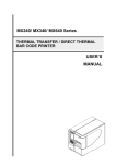
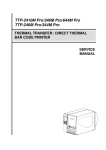
1.1. Overview
Front View
1
5
2
6
3
6.
P
o
w
e
r4
L
E
D
i
n
d
i
LED indicators
c
a
Touch screen LCD display
t
Front panel buttons
o
rUSB host x 2
Media view window
Paper exit chute
7.
Media cover
1.
2.
3.
4.
5.
7
Pr
in
t
h
e
a
d
1
MX240/ MX340/ MX640
Bar Code Printer Service Manual
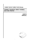
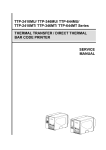
Interior View
5
6
1
7
Pr
in
t
h
e
a
d8
2
9
Pr
in
t Pr
h in
e t
a h
d e
a
d
3
P
o
w
1.e
r
2.L
3.E
D
i
4.n
d
i
5.c
a
6.t
o
r
10
4
Pri
nt
he
ad
Ribbon rewind spindle
Print head release lever
Media sensor position
adjustment knob
Rear paper feed roller
release lever
Ribbon supply spindle
Ribbon tension adjustment
knob
7.
Label supply spindle
8.
Rear label guide
9.
Fan-fold media entrance chute
10.
Print head pressure adjustment knobs
11.
Platen roller
12.
Print head
13.
Media sensor
14.
Front label guide
2
11
12
13
14
Pri
nt
he
ad
Pri
nt
hea
d
Pri
nt
he
ad
Pri
nt
hea
d
MX240/ MX340/ MX640
Bar Code Printer Service Manual
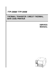
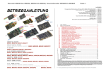
Rear View
4
US
B6
int
erf
ac
e
5
1
7
10
8
USB
inte
rfac
9e
3
2
1. External label entrance chute
2. Power cord socket
Pr
in
t
h
e
a
d
3. Power switch
4. External Bluetooth or WiFi module (Option)
5. RS-232C interface
6. GPIO interface (Option)
7. Ethernet interface
8. SD* card socket
9. USB interface
10. Centronics interface
11. USB host x 2 (ption)
3
Pri
nt
hea
d
11
Pri
nt
hea
d
MX240/ MX340/ MX640
Bar Code Printer Service Manual
* Recommended SD card specification.
SD card spec
SD card capacity
Approved SD card manufacturer
SDHC Class 10
32 GB
Transcend, Kingston, Sandisk
SDHC Class 10
16 GB
Kingston
Class 4
microSD 4 GB
Transcend, Kingston
Class 10
microSD 8 GB
Transcend, Kingston, Sandisk
Class 10
microSD 16 GB
Kingston, Sandisk
Class 10
microSD 32 GB
Kingston
Class 10 UHS-I
microSD 16 GB
Transcend, Sandisk
Class 10 UHS-I
microSD 32 GB
Transcend, Sandisk
- The DOS FAT file system is supported for the SD card.
- Folders/files stored in the SD card should be in the 8.3 filename format
- The miniSD/microSD card to SD card slot adapter is required.
4
MX240/ MX340/ MX640
Bar Code Printer Service Manual
2. ELECTRONICS
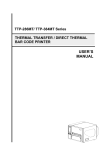
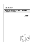
2.1 Summary of Board Connectors
5
MX240/ MX340/ MX640
Bar Code Printer Service Manual
Main board
Connector
Description
1
USB Host connector
2
Front USB Host connector
3
WiFi Module connector
4
Parallel Port board connector
5
GPIO interface board connector
6
Head open sensor connector
7
Gap sensor connector
8
Ribbon encoder sensor connector
9
Power supply output (24V DC) connector
10
BM Sensor connector
11
Paper roller open sensor connector
12
LCD Power & LED Power connector
13
Paper Distance Sensor connector
14
RFID module connector
15
Print head connector
16
LCD panel connector
17
Ribbon end sensor connector
18
TPH Power (24V DC) connector
19
Stepping motor connector
20
DC motor connector
21
Cutter/peel-off connector
22
Paper REWIND connector
23
Micro processor
24
Paper damper sensor connector
25
RS-232C connector
26
Ethernet interface
27
SD card socket
28
USB interface
29
USB host x 2 (Option)
6
MX240/ MX340/ MX640
Bar Code Printer Service Manual
2.2 Interface Pin Configuration
RS-232C
PIN
CONFIGURATION
1
+5 V
2
TXD
3
RXD
4
CTS
5
GND
6
RTS
7
N/C
8
RTS
9
N/C
USB
PIN
CONFIGURATION
1
N/C
2
D-
3
D+
4
GND
Ethernet
PIN
CONFIGURATION
1
Tx+
2
Tx-
3
Rx+
4
N/C
5
N/C
6
Rx-
7
N/C
8
N/C
7
MX240/ MX340/ MX640
Bar Code Printer Service Manual
3. MECHANISM
3.1 Remove the Lower Front Panel
Remove 2 screws to remove lower front panel.
Screws
8
MX240/ MX340/ MX640
Bar Code Printer Service Manual
3.2 Remove the Electronics Cover
1. Open printer media cover to remove 1 screw inside the printer.
2. Remove 6 screws on electronics cover.
Screws
9
MX240/ MX340/ MX640
Bar Code Printer Service Manual
3. Open the media cover about 20 ~30 degree then take electronics cover out from the
printer. Please refer to the following pictures.
Electronics cover
Step 2: Take out the
electronics cover
Step 1: Open
the media cover
about 20~30
degrees
10
MX240/ MX340/ MX640
Bar Code Printer Service Manual
3.3 Remove the Media Cover
1. Remove the electronics cover.
2. Remove 3 screws from each hinge. Be careful the media cover may fall out from the
printer.
3. Take out the media cover from the printer.
Screws
11
MX240/ MX340/ MX640
Bar Code Printer Service Manual
3.4 Replacing the Platen Roller Assembly
1. Open printer media cover.
2. Disengage print head release lever.
3. Remove 3 screws from the platen holder.
Screws
4. Take out the platen holder, tear bar and platen roller assembly and replace a new platen
roller assembly.
Platen roller assembly
Holder
5. Reassemble the parts in the reverse procedures.
12
MX240/ MX340/ MX640
Bar Code Printer Service Manual
3.5 Replacing the Print head ASS’Y
1. Loosen the print head secure screw counterclockwise until it can be taken out from the
mechanism.
2. Disengage the print head release lever.
3. Carefully disconnect connectors from the print head assembly. Please do not pull the
cable to right and left side alternatively in order to disconnect it from the print head
connector. Please use the flat screw driver to push at the key in the middle of the
connector. When the connector becomes loose from the print head connector, you can
disconnect it.
13
MX240/ MX340/ MX640
Bar Code Printer Service Manual
4. Remove/Replace the print head assembly.
5. Connect the print head cable and carefully slide print head assembly into the print
mechanism. Make sure the two locating protrusion pins on the print mechanism mounting
plate snap into the locating holes on the print head.
Locating
protrusions
Locating
protrusions
Locating
holes
Locating
holes
14
MX240/ MX340/ MX640
Bar Code Printer Service Manual
Locating
holes
Locating
holes
6. Check the print head has been totally closed to the print mechanism before secure the
print head by the previously removed thumbscrew.
7. Reassemble the parts in the reverse procedures.
Note: Please use the come with new print head secure screw to replace the print head
assembly. DO NOT re-use the original screw.
15
MX240/ MX340/ MX640
Bar Code Printer Service Manual
3.6 Replacing the LCD Panel Module
1. Follow the previous step to remove the electronics cover.
2. Remove the marked fix LCD panel module two screws.
3. Remove the module connecting cable & harness.
16
MX240/ MX340/ MX640
Bar Code Printer Service Manual
4. Reassemble the parts in the reverse procedures.
3.7 Replacing the LCD Control PCB-A & LCD Touch Panel
Assembly
1. Remove the FPC harness from the LCD control PCB-A
2. Remove the marked four fix screws from the LCD control PCB-A, then you can take off
the PCB-A
3. Remove the four fix screws from the LCD holder, then you can take off the holder & touch
panel.
17
MX240/ MX340/ MX640
Bar Code Printer Service Manual
Touch panel
4. Reassemble the parts in the reverse procedures.
18
LCD holder
MX240/ MX340/ MX640
Bar Code Printer Service Manual
3.8 Replacing the Front Panel Buttons Rubber Pad & Buttons
Control PCB-A
1. Remove the marked four fix screws from the Buttons control PCB-A , then you can take off
the button control PCB-A & buttons rubber pad.
2. Reassemble the parts in the reverse procedures.
19
MX240/ MX340/ MX640
Bar Code Printer Service Manual
3.9 Replacing the Label Supply Spindle
1. Remove the marked fix screw from the label supply spindle.
2. Draw out the label supply spindle for replacement.
3. Reassemble the parts in the reverse procedures.
20
MX240/ MX340/ MX640
Bar Code Printer Service Manual
3.10 Replacing the Label Supply Spindle DC Motor
1. Please refer to the power supply change procedures to remove the marked four fix
screws & cable. Then you can see the DC motor.
2. Remove the marked fix two screws from the DC motor
Remove the DC motor cable connector from the main board.
3. Then you can remove the DC motor.
21
MX240/ MX340/ MX640
Bar Code Printer Service Manual
4.
Reassemble the parts in the reverse procedures.
22
MX240/ MX340/ MX640
Bar Code Printer Service Manual
3.11 Replacing the Power Supply Unit
1. Refer to section 3.1 to remove the electronics cover.
2. Remove 4 screws and 2 connectors.
---- Connector
---- Screw
3. Remove/Replace the power supply unit.
4. Reassemble the parts in the reverse procedures.
23
MX240/ MX340/ MX640
Bar Code Printer Service Manual
3.12 Replacing Multi-interface Board
1. Refer to section 3.1 to remove the electronics cover.
2. Remove 2 screws to loosen the parallel port.
Screws
3. Remove 2 screws and one FPC cable from the connector.
Screws
FPC cable
24
MX240/ MX340/ MX640
Bar Code Printer Service Manual
4. Remove/Replace the multi-interface board.
5. Reassemble the parts in the reverse procedures.
25
MX240/ MX340/ MX640
Bar Code Printer Service Manual
3.13 Replacing the Main Board
1. Refer to section 3.1 to remove the electronics cover.
(Refer to section 3.4 to remove the multi-interface board.)
2. Remove 2 screws to loosen the serial port.
Screws
3. Remove 2 copper pillars, 3 screws, and all of the connectors from the main board
Copper pillars
Screws
26
MX240/ MX340/ MX640
Bar Code Printer Service Manual
4. Remove/Replace the main board.
5. Reassemble the parts in the reverse procedures.
27
MX240/ MX340/ MX640
Bar Code Printer Service Manual
3.14 Replacing the Stepping Motor Assembly
1. Refer to section 3.1 to remove the electronics cover.
2. Remove 4 screws and one connector on the stepping motor assembly.
---- Connector
---- Screw
3. Remove/Replace the stepping motor assembly (including belt, gears, stepping motor)
4. Reassemble the parts in the reverse procedures.
28
MX240/ MX340/ MX640
Bar Code Printer Service Manual
3.15 Replacing the Gap/Black Mark Sensor Module
1. Refer to section 3.1 to remove the electronics cover.
2. Disconnect the gap/black mark sensor connectors from the main board.
Gap/black mark
sensor connector
3. Pull out the media sensor module.
4. Remove/Replace the gap/black mark sensor.
5. Reassemble the parts in the reverse procedures.
29
MX240/ MX340/ MX640
Bar Code Printer Service Manual
3.16 Cutter Module Installation (Option)
1. Loose 2 screws to take out the lower front panel.
Screw
Screw
2. Take out the lower front panel in the right direction as red arrow indicated below.
30
MX240/ MX340/ MX640
Bar Code Printer Service Manual
3. Plug the cutter mini DIN cable connector into the cutter/peel-off connector. The triangle
mark on the connector must be at the front side.
4. Put 2 locating protrusions into locating holes as red arrows indicated.
31
MX240/ MX340/ MX640
Bar Code Printer Service Manual
5. Fasten the 2 screws.
32
MX240/ MX340/ MX640
Bar Code Printer Service Manual
3.17 Peel-off Kit Installation (Option)
Peel-off Kit parts list:
Peel-off Sensor
Module
Peel-off Roller
Module
Rewind Spindle
Module with 4
screws
A. Peel-off Sensor Module Installation
1. Loose 2 screws to take out the lower front panel.
Screw
Screw
33
MX240/ MX340/ MX640
Bar Code Printer Service Manual
2. Take out the lower front panel in the right direction as red arrow indicated.
3. Plug the peel sensor mini DIN cable connector into the cutter/peel-off connector. The
triangle mark on the connector must be at the front side.
34
MX240/ MX340/ MX640
Bar Code Printer Service Manual
4. Put 2 locating protrusions into locating holes as red arrows indicated.
5. Fasten the 2 screws back into the fixing holes.
Finished peel-off sensor module installation.
35
MX240/ MX340/ MX640
Bar Code Printer Service Manual
B. Peel-off Roller Module Installation
1.
Turn the thumb screw on the peel-off roller module in the counterclockwise direction
until taking out the screw.
2. There is a locating hole between media sensor and rear paper-feed roller (most right
one).
36
MX240/ MX340/ MX640
Bar Code Printer Service Manual
3. Put the shaft of the peel-off roller module into the locating hole.
4. After putting shat into locating hole, at certain angle, the module would not be able to
put inside.
37
MX240/ MX340/ MX640
Bar Code Printer Service Manual
5. Please turn the module in the clockwise direct to put the module inside.
2
1
6. Put back the golden color screw, and turn it in the clockwise direction to fix the screw.
38
MX240/ MX340/ MX640
Bar Code Printer Service Manual
7. Pushing the peel-off roller module upward.
8. After hearing the click sound, the module is fixed to its position without dangling.
Finished the installation of peel-off roller module.
39
MX240/ MX340/ MX640
Bar Code Printer Service Manual
C. Rewind Spindle Installation.
1. Remove 4 screws below the label supply spindle to take out the rewind spindle cover.
2. Put the whole rewind spindle module inside the hole after taking out the cover.
Make sure the direction of the module is same with left side picture.(small PCB is on
the bottom and the motor is on the top of module)
40
MX240/ MX340/ MX640
Bar Code Printer Service Manual
3. Using screws which come with module to fix the whole rewind spindle module.
4. Connect the 8-pins connector into main board socket.(Nearest socket)
41
MX240/ MX340/ MX640
Bar Code Printer Service Manual
3.18 Internal Rewinding Kit Installation (Option)
Internal rewinding kit parts list:
1. Loose 2 screws to take out the lower front panel.
Screw
Screw
42
MX240/ MX340/ MX640
Bar Code Printer Service Manual
2. Take out the lower front panel in the right direction as red arrow indicated.
3. Put 3 locating protrusions into locating holes.
43
MX240/ MX340/ MX640
Bar Code Printer Service Manual
4. Fasten the 2 screws back into the fixing holes.
5. Remove 4 screws below the label supply spindle to take out the rewind spindle cover.
6. Fasten the 3 screws to fix the cover as below.
44
MX240/ MX340/ MX640
Bar Code Printer Service Manual
7. Put the whole rewind spindle module inside the hole.
Make sure the direction of the module is same as picture. (Small PCB is on the bottom
and the motor is on the top of module)
8. Using screws which come with module to fix the whole rewind spindle module.
45
MX240/ MX340/ MX640
Bar Code Printer Service Manual
9. Connect the 8-pins connector into main board socket. (Nearest socket)
10. Install the rewind label guide to the hole as picture showing. Fix it by one screw.
46
MX240/ MX340/ MX640
Bar Code Printer Service Manual
4. TROUBLESHOOTING
4.1 Common Problems
The following guide lists the most common problems that might be encountered when
operating this bar code printer. If the printer still does not function after all suggested
solutions have been invoked, please contact the Customer Service Department of your
purchased reseller or distributor for assistance.
Problem
Possible Cause
Recovery Procedure
Power indicator does * The power cord is not properly
connected.
not illuminate
Carriage Open
* The printer print head release lever or
Rear paper feed roller
release lever is not engaged.
No Ribbon
No Paper
Paper Jam
* Plug the power cord in printer and outlet.
* Switch the printer on.
* Please engage the release levers.
* Running out of ribbon.
* The ribbon is installed incorrectly.
* Supply a new ribbon roll.
* Please refer to the steps in user’s manual to
reinstall the ribbon.
* Running out of label.
* The label is installed incorrectly.
* Gap/black mark sensor is not
calibrated.
* Gap/black mark sensor is not on the
media
* Gap/black mark sensor is not set
correctly for the media
* Make sure media width and height are
set exactly same as actual media width
and height.
* Labels may be stuck inside the printer
mechanism or media sensor
* Supply a new label roll.
* Please refer to the steps in user’s manual to
reinstall the label roll.
* Calibrate the gap/black mark sensor.
* Align the media sensor on top of the media
or black mark or nutch.
* Select the correct sensor for the media
* Calibrate the gap/black mark sensor.
* Set media width and height correctly.
* Remove the stuck label inside the print
mechanism or at the media sensor
* If the peeler module is installed and function
is enabled, please remove the peeled label.
* If there is no peeler module installed, please
switch off the printer and install it.
* Check if the peeler module cable connector
is plugged correctly.
Take Label
* Peel function is enabled.
47
MX240/ MX340/ MX640
Bar Code Printer Service Manual
* If the cutter module is installed, please press
UP or DOWN key to rotate the cutter blade
up (forward) or down (backward) to make
UP:
Fwd.
* Cutter jammed.
the blade back to the right position.
* There is no cutter installed on the
DOWN:
Rev.
* Remove the label.
printer.
* Make sure the thickness of label is less than
* Cutter PCB is damaged.
MENU:
Exit
200 g/m2 (for regular cutter) or 300 g/m2
(for heavy duty cutter).
* Replace a cutter PCB.
* Re-connect cable to interface.
* If using serial cable,
- Please replace the cable with pin to pin
connected.
- Check the baud rate setting. The default
baud rate setting of printer is 9600,n,8,1.
* If using the Ethernet cable,
- Check if the Ethernet RJ-45 connector
green LED is lit on..
- Check if the Ethernet RJ-45 connector
amber LED is blinking.
- Check if the printer gets the IP address
when using DHCP mode.
- Check if the IP address is correct when
* Cable is not well connected to serial or
using the static IP address.
USB interface or parallel port.
- Wait a few seconds let the printer get the
* The serial port cable pin configuration
Not Printing
communication with the server then check
is not pin to pin connected.
the IP address setting again.
* Chang a new cable.
* Ribbon and media are not compatible.
* Verify the ribbon-inked side.
* Reload the ribbon again.
* Clean the printhead.
* The print density setting is incorrect.
* Printhead’s harness connector is not well
connected with printheat. Turn off the printer
and plug the connector again.
* Check if the stepping motor is plugging in
the right connector.
* Check your program if there is a command
PRINT at the end of the file and there must
have CRLF at the end of each command
line.
* Delete unused files in the FLASH/DRAM.
* The max. numbers of file of DRAM is 1024
files.
Memory full
* The space of FLASH/DRAM is full.
* The max. user addressable memory space
( FLASH / DRAM )
of DRAM is 8192 KB
* The max. user addressable memory space
of FLASH is 80 MB.
* SD card is damaged.
* Use the supported capacity SD card.
SD card is unable to * SD card doesn’t insert correctly.
* Insert the SD card again.
*
Use
the
non-approved
SD
card
* The supported SD card spec are listed in
use
manufacturer.
section 1.1.
48
MX240/ MX340/ MX640
Bar Code Printer Service Manual
Poor Print Quality
* Reload the supply.
* Clean the print head.
* Clean the platen roller.
* Adjust the print density and print speed.
* Run printer self-test and check the print
head test pattern if there is dot missing in
* Ribbon and media is loaded incorrectly
the pattern.
* Dust or adhesive accumulation on the
* Change proper ribbon or proper label
print head.
media.
* Print density is not set properly.
*Please refer to section 4.5 for avoiding the
* Print head element is damaged
ribbon wrinkle
* Ribbon and media are incompatible.
* The print head pressure is not set
* If the label thickness is more than 0.22 mm,
properly
the print quality might not be good enough,
please adjust the heater line adjustment
screw counter clockwise to get the best print
quality.
* The release lever does not latch the print
head properly.
LCD panel is dark and * The cable between main PCB and LCD * Check if the cable between main PCB and
LCD is secured or not.
keys are not working. panel is loose.
LCD panel is dark but * The printer initialization is
unsuccessful.
the LEDs are light.
* Turn OFF and ON the printer again.
* Initialize the printer.
LCD panel is dark and
LEDs are lit on, but
the label is feeding
* The LCD panel harness connector is
loose.
* The LCD panel harness connector is
plugged upside down.
forward.
Ribbon encoder
* The ribbon encoder sensor connector
sensor doesn’t work. is loose.
Ribbon end sensor
doesn’t work.
Peel sensor is not
working.
* The connector is loose.
* Check the connector.
* The ribbon sensor hole is covered with * Clear the dust in the sensor hole by the
dust.
blower.
* Peel sensor is not located on the
* Make sure that the media goes through the
correct position.
Peel sensor.
* The connector is loose.
* Plug the connect cable correctly.
Cutter is not working. * The connector is loose.
* Plug in the connect cable correctly.
Label feeding is not
stable (skew) when
* The media guide does not touch the
edge of the media.
printing.
Skip labels when
printing.
* Fasten the connector.
* If the label is moving to the right side, please
move the label guide to left.
* If the label is moving to the left side, please
move the label guide to right.
* Check if label size is setup correctly.
* Label size is not specified properly.
* Calibrate the sensor by Auto Gap or Manual
* Sensor sensitivity is not set properly.
Gap options.
* The media sensor is covered with dust. * Clear the GAP/Black mark sensor by
blower.
Missing printing on
the left or right side of * Wrong label size setup.
* Set the correct label size.
label.
49
MX240/ MX340/ MX640
Bar Code Printer Service Manual
RTC time is incorrect
when reboot the
* The battery has run down.
* Check if there is a battery on the main
board.
* The installation is incorrect.
* Check if the board is plugged in the right
connector.
* Power switch OFF and ON too fast.
* Turn off the printer and wait all LEDs are
dark, and turn on the printer again.
* Printhead pressure is incorrect.
* Ribbon installation is incorrect.
* Media installation is incorrect.
* Print density is incorrect.
* Media feeding is incorrect.
* Please refer to the 5.2 chapter.
* Please set the suitable density to have good
print quality.
* Make sure the label guide touch the edge of
the media guide.
printer.
Multi interface board
doesn’t work.
Power and Error LEDs
are blinking fast.
Wrinkle Problem
Gray line on the blank * The printhead is dirty.
* The platen roller is dirty.
label
Irregular printing
* Clean the printhead.
* Clean the platen roller.
* The printer is in Hex Dump mode.
* The RS-232 setting is incorrect.
50
* Turn off and on the printer to skip the dump
mode.
* Re-set the Rs-232 setting.
MX240/ MX340/ MX640
Bar Code Printer Service Manual
4.2 Mechanism Fine Adjustment to Avoid Ribbon Wrinkles
This printer has been fully tested before delivery. There should be no ribbon wrinkle
presented on the media for general-purpose printing application. Ribbon wrinkle is related to
the media width, thickness, print head pressure balance, ribbon film characteristics, print
darkness setting…etc. In case the ribbon wrinkle happens, please follow the instructions
below to adjust the printer parts.
The pressure position can be adjusted by using a coin. Please use a coin
to release the fixing screws as below show.
Fixing
screws
When using label its width is smaller than 2 inch. Please release the right
side of pressure knob. Only use left side pressure and you may adjust the
Pressure
position
left side position, too. Once you find a position that has balance pressure
on the label, the wrinkle will disappear.
51
MX240/ MX340/ MX640
Bar Code Printer Service Manual
The print head pressure adjustment knob has 5 levels of settings. “1” is
the lowest pressure and “5” is the maximum pressure. Clockwise direction
adjustment is to increase the print head pressure. Please only turn the
pressure knobs in clockwise direction.
Pressure
Volume
Print head
pressure
adjustment
knobs
1. Wrinkle happens from label lower
Symptom
left to upper right direction (“ˊ”)
2. Wrinkle happens from label lower
right to upper left direction (“ˋ”)
Feed direction
Wrinkle
Example
If the wrinkle on the label starts from If the wrinkle on the label starts from
the lower left side to upper right side, the lower right side to upper left
please do following adjustment.
side, please do following
1. Decrease the right side print head adjustment.
pressure adjustment knob setting 1 1. Decrease the left side print head
level per each adjustment then
pressure adjustment knob setting
print the label again to check if
1 level per each adjustment then
wrinkle is gone.
print the label again to check if
2. If the right side print head
wrinkle is gone.
adjustment knob setting has been 2. If the left side print head
set to index 1 (the lowest pressure adjustment knob level has been
index), please increase the left side set to index 1 (the lowest index),
please increase the right side print
print head pressure.
head pressure.
52
MX240/ MX340/ MX640
Bar Code Printer Service Manual
4.3 Adjusting Heater Line
1. Release 2 lock screws before you start to adjusting heater line screws.
Heater line lock screws
Heater line lock screws
Heater line adjust screw
Heater line adjust screw
2. Adjust heater line by right-side and left-side heater-line adjusting screws.
53
MX240/ MX340/ MX640
Bar Code Printer Service Manual
3. In our standard testing procedure, we use Fasson semi-gloss paper and print a black bar
as below picture.
4. Please do not use too high density for adjusting heater line. Because it would not be easy
seeing the uneven printing if using too high density to print the black bar.
For 200dpi printer, below is example command line for adjusting heater line.
SIZE 102.5 mm, 63.5 mm
GAP 0.08,0
SPEED 8
DENSITY 0
REFERENCE 0,48
DIRECTION 0,0
SET TEAR ON
CLS
BAR 8,18,99*8,30*8
TEXT 142, 360, "ROMAN.TTF", 0, 8, 8, "SPEED : " +
GETSETTING$("CONFIG","TSPL","SPEED")
TEXT 142, 390, "ROMAN.TTF", 0, 8, 8, "DENSITY : " +
GETSETTING$("CONFIG","TSPL","DENSITY")
TEXT 142,420, "ROMAN.TTF",0,1,8,"S/N : " +
54
MX240/ MX340/ MX640
Bar Code Printer Service Manual
GETSETTING$("SYSTEM","INFORMATION","SERIAL")
PRINT 1
5. The lighter black bar may like left picture.
6. But sometime you can see one side has lighter density as below picture.
7. For this situation, please adjust right side heater line adjustment knob by clockwise
direction until you see good density full average black.
55
MX240/ MX340/ MX640
Bar Code Printer Service Manual
Sometimes when right side is ok, left size may become a little white. In this time you may
need to adjust left side knob.
8. Until both side is full-average black , like the first one picture.
Or like left side picture.
9. If you keep turning the heater over the best position, it may look like below picture again:
Right side is lighter again.
56
MX240/ MX340/ MX640
Bar Code Printer Service Manual
10. If this happens, please turn the heater line button in opposite direction. In the previous
case, you may turn clockwise direction. Until you see the even picture I show you.
11. Then after adjusting it, lock the 2 locking screws to fix the heater line position.
PS:
For different thickness label, you may need to print out such pattern to see if this
heater line is fit with this heat line position or not.
If you find that even with the lowest speed and highest density, the density is still
not enough, you can try to do this test to adjust heat line.
57
MX240/ MX340/ MX640
Bar Code Printer Service Manual
5. MAINTENANCE
This session presents the clean tools and methods to maintain your printer.
Please use one of following material to clean the printer.
Cotton swab (Head cleaner pen)
Lint-free cloth
Vacuum / Blower brush
100% ethanol
2.
The cleaning process is described as following
Printer Part
Method
Interval
1. Always turn off the printer
Clean the print head when changing a
before cleaning the print head. new ribbon roll
2. Allow the print head to cool for
a minimum of one minute.
3. Use a cotton swab (Head
cleaner pen) and 100% ethanol
to clean the print head surface.
Print Head
Platen Roller
1. Turn the power off.
Clean the platen roller when changing
2. Rotate the platen roller and
a new ribbon roll
wipe it thoroughly with a cotton
swab, or lint-free cloth soaked
with clean water..
Tear Bar/Peel
Use the lint-free cloth with 100% As needed
58
MX240/ MX340/ MX640
Bar Code Printer Service Manual
Bar
ethanol to wipe it.
Sensor
Compressed air blower or
vacuum
Monthly
Exterior
Wipe it with water-dampened
cloth
As needed
Interior
Brush or vacuum
As needed
Note:
Do not touch printer head by bare hand. If you touch it careless, please use ethanol to
clean it.
Please use 100% Ethanol. DO NOT use medical alcohol, which may damage the printer
head.
Regularly clean the print head and supply sensors once change a new ribbon to keep
printer performance and extend print head life.
59
MX240/ MX340/ MX640
Bar Code Printer Service Manual
UPDATE HISTORY
Date
2014/8/5
2014/12/12
2015/1/8
Content
Editor
Add section 3.18 (Internal rewinding kit installation)
Camille
Modify pictures for key feature change
Camille
Modify section 3.2
Camille
60
Corporate Headquarters
9F., No.95, Minquan Rd., Xindian Dist.,
New Taipei City 23141, Taiwan (R.O.C.)
TEL: +886-2-2218-6789
FAX: +886-2-2218-5678
Web site: www.tscprinters.com
TSC Auto ID Technology Co., Ltd. E-mail: [email protected]
[email protected]
61
Li Ze Plant
No.35, Sec. 2, Ligong 1st Rd., Wujie Township,
Yilan County 26841, Taiwan (R.O.C.)
TEL: +886-3-990-6677
FAX: +886-3-990-5577