1
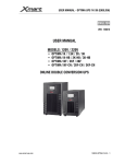
Service Manual
Star T3/T3R UPS
1kVA~3kVA 220VAC
www.allis.com.tw
ST3 1-3kVA Service Manual Rev.1
Content
1. PSDR Introduction............................................................................................................................ 1
1.1 1 kVA PSDR ............................................................................................................................ 1
1.2 2/3 kVA PSDR ......................................................................................................................... 1
2. Fault and Warning ............................................................................................................................ 2
3. Troubleshooting................................................................................................................................ 3
3.1 Quick Start............................................................................................................................... 3
3.2 PFC Analysis:.......................................................................................................................... 4
3.3 Boost Analysis......................................................................................................................... 5
3.4 Inverter Analysis...................................................................................................................... 6
3.5 SPS Module Analysis .............................................................................................................. 7
3.6 1A Charger Module Analysis ................................................................................................... 8
3.7 IGBT Driver Module Analysis .................................................................................................. 9
4. Final testing.................................................................................................................................... 10
ST3 1-3kVA Service Manual Rev.1
1. PSDR Introduction
1.1 1 kVA PSDR
d
1.2 2/3 kVA PSDR
,,
c
e
i
f
g
d
j
h
e
c
g
i
j
e
f
1. Charger Module
2. Fan driver
3. Inverter IGBT Driver Module
4. PFC IGBT Driver Module
5. PFC Control Module
6. Boost IGBT Driver Module
7. SPS Module
8. Boost Control Module
Allis Electric
Page 1 of total 12
September 2006
ST3 1-3kVA Service Manual Rev.1
2. Fault and Warning
LCD & LED Status /
Audible Alarms
AC: OK
BATT: OK
TEMP Fail
Fault
Warning
Normal
y
y
y
y
y
y
UPS in Bypass Mode.
The alarm beeps continuously.
AC: OK
BATT: OK
Inverter Fail
Fault
Warning
Normal
UPS in Bypass Mode.
Fault LED lights up and the
alarm beeps continuously.
AC: OK
BATT: LOW
Normal Mode
Fault
Warning
Normal
UPS in Normal Mode, but
battery capacity is low.
The alarm beeps once every
second for battery low.
AC: OK
BATT: OK
DC_BUS Fail
Fault
Warning
Normal
Possible Cause
1. Fan fail.
2. Temperature is
higher than
allowed operation
temperature.
1.
2.
3.
4.
UPS stop working.
The alarm beeps continuously.
Allis Electric
1.
2.
Inverter circuit
failed.
Inverter driver
failed.
PFC circuit failed.
Output shorted
Replace the fan.
Reduce ambient
temperature or O/P load.
1. Replace the Inverter
components or driver.
2. Replace the PFC
components or driver.
3. Remove the output
shorted.
1. Charger may
break down.
1.
Please replace charger
board.
1.
1.
Replace the Boost
components.
Replace the Inverter
components.
Replace the PFC
components.
Replace the BUS circuit
components.
2.
3.
4.
y
y
Action
Boost circuit
failed.
Inverter circuit
failed
PFC circuit failed
BUS circuit failed.
2.
3.
4.
Page 2 of total 12
September 2006
ST3 1-3kVA Service Manual Rev.1
3. Troubleshooting
3.1 Quick Start
Before any check of UPS, please check the components as listed in the following table. This action could help you find
problem quickly and make sure these components good or not first.
Possible Circuit Block
Coded Components
Description
Failure Mode
BAT FUSE
1K/3K:F1/F2;2K:F1
Fuse
Open
I/P FUSE (on PSDR)
F3,
Fuse
Open
Diode
Short or open
PFC Correction
2K/3K:D16, D17, REC02
1K:D10, D11, REC1
2K/3K:Q09,1K:Q14
IGBT
C-E short or open
D-S short or open
Push-Pull Booster
2K/3K:Q04, Q05, Q06Q07 MOSFET
1K:Q4, Q6, Q10Q11
Short or open
2K/3K:D05, D06, D07, D08 Power Diode
1K:D12, D13, D14, D15
C-E short or open
Inverter
2K/3K:Q13, Q14, Q15, Q16 IGBT
1K:Q12, Q13
Charger module
SPS module
Q2
D10,D11,D12,D13D15
Q201
D202,D203
MOSFET
Power Diode
MOSFET
Power Diode
D-S short or open
Short or open
D-S short or open
Short or open
If the fuse is open, replacing fuse only, DO NOT mean you have solved the problem. General
speaking, fuse open was caused by other failure of components; therefore, you must find the
real defective components and replace them, before restart the UPS.
Allis Electric
Page 3 of total 12
September 2006
ST3 1-3kVA Service Manual Rev.1
3. Troubleshooting
3.2 PFC Analysis:
In this section, some components you could check to see if failure occurs on PFC Correction circuit as shown below. Be
aware of F3 fuse open indicates failure of this block. Please replace all faulty components before re-start the UPS.
1kVA-PFC
2/3kVA-PFC
Step
1
2
3
4
Checked components
F3
2K/3K:Q09(GS)
1K:Q14(GS)
2K/3K:D16,D17
1K:D10,D11
2K/3K:REC02 (+,∼),(∼,-)
1K:REC1 (+,∼),(∼,-)
Instrument
function
Ω
Ω
Reference
Value
Short
46.8kΩ
Failure Mode
Open
Short or open
DIODE
0.418
Short or open
DIODE
0.46
Short or open
Action ltem: If all above-stated components are replaced well and UPS still can’t work, change PFC Module
and PFC IGBT driver module.
Allis Electric
Page 4 of total 12
September 2006
ST3 1-3kVA Service Manual Rev.1
3. Troubleshooting
3.3 Boost Analysis
General speaking, the most distinct phenomenon of failure on this section is F1 and F2. Open finding this will be very
helpful to repair them.
1kVA-Boost
2/3kVA-Boost
Step
1
2
3
Checked components
F1,F2
2K/3K:Q04~Q07 (G.S)
1K:Q4,Q6,Q10,Q11(G.S)
2K/3K:D05,D06,D07,D08
1K:D12,D13,D14,D15
Instrument
function
Ω
Ω
Reference
Value
short
23.49kΩ
Failure Mode
open
short or open
DIODE
0.41
short or open
Action ltem:
(1) Make sure the DC fuses with same rating as original ones for replacement. Otherwise, unpredictable
danger might happen.
(2) If all above-stated components are replaced well and UPS still can’t be DC start, change Boost Control
Module.
Allis Electric
Page 5 of total 12
September 2006
ST3 1-3kVA Service Manual Rev.1
3. Troubleshooting
3.4 Inverter Analysis
1kVA-Inverter
2/3kVA-Inverter
Step
1
2
Checked components
2k/3k:Q14,Q13,Q16,Q15 (G,S) Ω
1k:Q12,Q13 (G,S)
Ω
2k/3k: D30,D31,D32,D33
1k: D21,D22
Instrument
function
Reference
Failure Mode
Value
23.5kΩ
Short or open
70
46.6
Short or open
Action ltem: If fail condition stated in resistance R110, R106, R117 and R119 of 2/3kVA and R53 and R37 of
1kVA, there is high possibility that the corresponding photo couplers are damaged, change the Inverter IGBT
driver module
Allis Electric
Page 6 of total 12
September 2006
ST3 1-3kVA Service Manual Rev.1
3. Troubleshooting
3.5 SPS Module Analysis
1 kVA-SPS Module
2/3 kVA-SPS Module
Step
1
2
Checked components
Q201(S,D)
U01 (3845) PIN 5-6
PIN 5-7
PIN 5-8
PIN 6-8
Instrument
function
DIODE
Ω
Reference
Failure Mode
Value
0.42
Short or open
46.7K
Too low
38K
4.31K
50.9K
Action ltem: Even If the input source connected with UPS, the UPS still does not work. The high possible
cause is on SPS Module.
Allis Electric
Page 7 of total 12
September 2006
ST3 1-3kVA Service Manual Rev.1
3. Troubleshooting
3.6 1A Charger Module Analysis
1 kVA-Charger Module
2/3 kVA-Charger Module
Step
1
2
3
Checked components
Q2(S,D)
U07 (3845) PIN 5-6
PIN 5-7
PIN 4-8
D10.D11,D12,D13,D15
Instrument
function
DIODE
Ω
DIODE
Reference
Failure Mode
Value
0.45
Short or open
47K
Too low
20K
7.48K
0.45
Short or open
Action ltem: UPS can work on bypass Mode normally when the input source connected, but it can not
start-up completely. The high possible cause is on Charger Module.
Allis Electric
Page 8 of total 12
September 2006
ST3 1-3kVA Service Manual Rev.1
3. Troubleshooting
3.7 PFC / Boost / Inverter IGBT Driver Module Analysis
1 kVA- IGBT Driver Module
2/3 kVA- IGBT Driver Module
Step
1
2
Checked components
U701.PIN2/PIN3
Q702(E.B,E.C)
Q703(B.E,C.E)
Allis Electric
Instrument
function
DIODE
DIODE
Reference
Failure Mode
Value
0.54
Short or open
0.64,1.00
Short or open
Page 9 of total 12
September 2006
ST3 1-3kVA Service Manual Rev.1
4. Final testing
After you have replaced all defective components on power stage (PSDR), please follow the steps as below.
Step 1. Connect with control board.
Step 2. Re-plug fan wires into connector FAN1 and FAN2.
1 kVA
Step 1
Step 2
2/3 kVA
Step 1
Step 2
Allis Electric
Page 10 of total 12
September 2006
ST3 1-3kVA Service Manual Rev.1
4. Final testing
Do not connect with AC power source yet.
Step 3. Supply DC voltage (96-110Vdc/3 Amp (limited current) for 2/3kVA, 36~41Vdc/3Amp for 1k) with DC power supply
via BAT(+) and BAT(-). Press the switch on front panel for more than 3 seconds, you will see "current limit" for a short time
on the DC power supply for about only 2 seconds, then UPS should be DC start (If UPS does not start successfully, and
LCD display off, replace the above procedure). If UPS fails to start up for several times or DC power supply is on
current-limit state continuously, there must be some defective components exist. Please follow the section 3 trouble
shooting to check again.
Step 4. If the UPS re-start normally, check the DC_BUS and output voltage.
- For 1kVA, DC_BUS: +340~365 and -340~365VDC, deviation between negative and positive voltage should be within
20VDC. Output Voltage: 220/230/240 +/-2%
- For 2kVA, DC_BUS: +340~365 and -340~365VDC, deviation between negative and positive voltage should be within
20VDC. Output Voltage: 220/230/240 +/-2%
- For 3kVA, DC_BUS: +340~365 and -340~365VDC, deviation between negative and positive voltage should be within
10VDC. Output Voltage: 220/230/240 +/-2%
1 kVA
Output Voltage: 220/230/240 +/-2%
DC_BUS: + 340~365VDC
®
®
DC_BUS: - 340~365VDC
-
Allis Electric
Page 11 of total 12
September 2006
ST3 1-3kVA Service Manual Rev.1
4. Final testing
2/3 kVA
®
DC_BUS: + 340~365VDC
Output Voltage: 220/230/240 +/-2%
®
DC_BUS: - 340~365VDC
-
Step 5. Connect with AC power source, then follow the step3 and step4 to check the DC_BUS and output voltage again. If
UPS fails to start up for several times, there must be some defective components exist. Please follow section 3 trouble
shooting to check again.
Allis Electric
Page 12 of total 12
September 2006