1
07-032 VW-VF10BG_TD
2/15/07
11:24 AM
Page a
TECHNICAL DATA
&
SERVICE MANUAL
With Virus Washer Function
1
Space Cleaning System
2
I
Floor-mounted model
VW-VF10BG
3
4
5
6
7
8
RoHS
G
This product does not contain any hazardous substances prohibited by the RoHS Directive.
WARNING
G
You are requested to use RoHS compliant parts for maintenance or repair.
G
You are requested to use lead-free solder.
854-6-4849-256000
REFERENCE No.
SM830156
07-032 VW-VF10BG_TD
2/15/07
11:24 AM
Page i
IMPORTANT
Safety Information
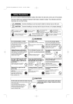
Be sure to read the following important safety information for safe and correct use of the product.
The items listed here represent important information related to safety. The indicators and their
meanings are as shown below.
WARNING
Incorrect handling or use may result in death or serious injury to the user.
CAUTION
Incorrect handling or use may result in injury to the user, or in property damage.
“Do not disassemble”:
Indicates that
disassembly is prohibited.
“Required”: Indicates a
required action.
“Prohibited”: Indicates a
prohibited action.
“Unplug”: Indicates that the power
cord must be unplugged.
“Electric Shock Danger” (Located
on main unit): Indicates that there
is the danger of electric shock.
“Do not touch”:
Indicates that contact
is prohibited.
“Do not wet”: Indicates that contact
with water is prohibited.
WARNING
Do not disassemble or modify.
Do not apply water.
Do not insert foreign objects.
Do not attempt to disassemble for repair or to
modify this system. Doing so may result in
fire, electric shock, or injury.
For repairs, consult with the
dealer where the product was
purchased.
Do not
Do not immerse this unit in water or apply
water to it.
Doing so may result in a short circuit and
electric shock.
Do not insert metal objects such as pins or
needles, or other foreign objects, into the
intake, outlet, or water tank installation port.
Doing so may result in injury due to
electric shock, or in abnormal
operation of the system.
Do not wet
disassemble
Unplug the power cord before
cleaning or servicing the system.
When cleaning or servicing the system, be
sure to first unplug the power cord.
Failure to do so may result in
electric shock or injury.
Do not damage the power cord.
Do not scratch, cut, modify, bend excessively,
pull on, twist, or otherwise damage the power
cord.
Damage to the power cord may
result in fire or electric shock.
Unplug
Do not use with any power other
than 220 – 240 V AC power.
Do not plug multiple cords into
the same outlet.
Do not use chlorine-based or
acidic detergents when cleaning
the water tank, unit, or filters.
Acidic
These detergents
may result in
deformation and
discoloration.
Prohibited
Remove dirt or dust from the
power plug.
Regularly remove any dirt or dust from the
power plug.
If dirt or dust accumulates on the
power plug, humidity or other
factors may cause an insulation
Required
failure, resulting in fire.
Do not plug or unplug the power
cord with
wet hands.
Doing so may result
in electric shock.
Prohibited
Chlorinebased
Doing so may result in fire, electric
shock, or damage to the system.
Prohibited
Prohibited
Insert the power plug securely, all
the way to the base.
Do not use a plug that cannot be fully
inserted or that is damaged. Do not use a
loose power outlet.
Doing so may result in electric
shock or in fire caused by over heating.
Prohibited
A leakage breaker is required.
Use a power source that includes a leakage
breaker.
Failure to do so may result in
electric shock or fire.
Required
Do not use insecticides or
aromatics.
Do not use insecticides, aromatics, or
mosquito coils while the unit is
operating.
Doing so can cause system
malfunction.
Required
Prohibited
CAUTION
Fill the water tank with fresh water every day.
Rinse out the water tank every day and keep it clean. Then be sure to refill it with fresh tap water.
If you continue to use the tank without cleaning it, sediment and water scale may decrease the performance of
the unit, or may cause the growth of mold or bacteria, resulting in odor.
Required
i
07-032 VW-VF10BG_TD
2/15/07
11:24 AM
Page ii
CAUTION
Do not place any containers that
contain liquid on top of the
system.
Do not perform cleaning while the
system is operating.
Doing so may result in electric shock or
injury.
Doing so may result in system
malfunction.
Prohibited
Do not obstruct the outlet.
Do not obstruct the air outlet with a curtain,
towel, or other item.
Doing so may result in system malfunction.
Prohibited
Be sure to securely reinstall all
components after cleaning.
Grasp the power plug when
unplugging the power cord.
Using the unit without the water tank, filter, or When unplugging the power cord, do not
other component securely installed
grasp the cord. Instead, be sure to grasp the
may result in system malfunction.
power plug at the end of the cord
and pull out the plug. Unplugging
the cord incorrectly may result in
Required
Required
electric shock, short circuit, or fire.
Install the system indoors, and
use in an environment between
5°C and 35°C.
Do not use the system with the
filter removed.
Dust entering into the system may cause
In a particularly cold environment, the freeze- system malfunction.
prevention function may be
activated, and the unit may not
operate even when the power
Required
switch is turned ON.
Required
Do not install in a location
exposed to dripping water.
Avoid installation in high
locations. Install in a flat and
stable location.
Doing so may result in system malfunction.
Observe this precaution in order to ensure
that the system functions correctly.
Failure to do so may result in the
unit tipping over due to earthquake
or contact by persons.
Required
Prohibited
When relocating or storing the product (if it will
not be used for a long period of time), drain the
electrolyzed water and dry the air purification
element.
Prohibited
Do not place any items on the
unit.
Do not climb onto the unit.
Doing so may result in system
malfunction, or in the unit tipping
over.
Prohibited
Install in a location where there is
little humidity, oil mist, or other
airborne substance.
Select a location for use that is free of
humidity, dust, oil smoke (oil particles
generated from cooking), and salt.
Failure to do so may result in
odors or in system malfunction.
Required
Secure space of 10 cm or more at
the left and right sides of the unit.
Also, allow servicing space of 100 cm or
more above and to the front of the unit.
Failure to do so may result in
system malfunction.
Required
This system is not able to break down or remove
toxic gasses and substances.
Be sure to open a window or otherwise ventilate
the interior of the room if a release occurs.
If the system is used for a long period in a
small room, open a window and ventilate
the room as necessary.
Required
Required
IMPORTANT INFORMATION
Be sure to use normal tap
(drinking) water.
Never use water from a water purifier, water
from a water heater, alkali ion water, mineral
water, well water, seawater, or other types of
water. These types of water cannot be
electrolyzed and can cause the growth of
mold or bacteria, resulting in odor.
Perform regular cleaning.
Follow the instructions under “Cleaning the
System,” in order to clean and maintain the
unit.
If the unit becomes especially dirty, mold may
grow, resulting in odor.
The electrolysis condition must
be set correctly according to the
water quality in the region where
the product is used.
For details, refer to “Setting the electrolysis
condition.”
Do not direct the discharged air
directly onto walls or furniture.
Do not allow the discharged air to directly
contact walls or furniture.
It may damage the walls or furniture, resulting
in stains.
ii
Do not unplug the power cord,
even if the unit will not be used
for a while.
Even when the unit is stopped, cleaning
inside the system is performed automatically.
Check that there is water in the water tank,
and do not unplug the power cord.
Be careful of freezing.
Freezing may result in system malfunction
and damage.
07-032 VW-VF10BG_TD
2/15/07
11:24 AM
Page iii
CONTENTS
Section 1:
Features . . . . . . . . . . . . . . . . . . . . . . . . . . . . . . . . . . . . . . . . . . . . . . . . . . . . . . 1-1
1. System Features . . . . . . . . . . . . . . . . . . . . . . . . . . . . . . . . . . . . . . . . . . . . . . . . . . . . . . . . . 1-2
2. Name and Function of Parts . . . . . . . . . . . . . . . . . . . . . . . . . . . . . . . . . . . . . . . . . . . . . . . . 1-2
Section 2:
Using this System . . . . . . . . . . . . . . . . . . . . . . . . . . . . . . . . . . . . . . . . . . . . . 2-1
1.
2.
3.
4.
5.
6.
7.
8.
9.
10.
11.
Section 3:
Before Using this System . . . . . . . . . . . . . . . . . . . . . . . . . . . . . . . . . . . . . . . . . . . . . . . . . . . 2-2
Precautions for Use . . . . . . . . . . . . . . . . . . . . . . . . . . . . . . . . . . . . . . . . . . . . . . . . . . . . . . . 2-5
Using the System . . . . . . . . . . . . . . . . . . . . . . . . . . . . . . . . . . . . . . . . . . . . . . . . . . . . . . . . . 2-6
Draining Procedure . . . . . . . . . . . . . . . . . . . . . . . . . . . . . . . . . . . . . . . . . . . . . . . . . . . . . . . 2-7
Draining and Drying Procedure . . . . . . . . . . . . . . . . . . . . . . . . . . . . . . . . . . . . . . . . . . . . . . 2-8
Troubleshooting . . . . . . . . . . . . . . . . . . . . . . . . . . . . . . . . . . . . . . . . . . . . . . . . . . . . . . . . . . 2-9
Trouble Diagnosis . . . . . . . . . . . . . . . . . . . . . . . . . . . . . . . . . . . . . . . . . . . . . . . . . . . . . . . . 2-10
Cleaning the System . . . . . . . . . . . . . . . . . . . . . . . . . . . . . . . . . . . . . . . . . . . . . . . . . . . . . 2-11
Storage (when the system will not be used for an extended period of time) . . . . . . . . . . . 2-12
Replacing Consumable Parts . . . . . . . . . . . . . . . . . . . . . . . . . . . . . . . . . . . . . . . . . . . . . . . 2-13
Declaration of Conformity . . . . . . . . . . . . . . . . . . . . . . . . . . . . . . . . . . . . . . . . . . . . . . . . . 2-14
Measuring The Water Sample . . . . . . . . . . . . . . . . . . . . . . . . . . . . . . . . . . . . 3-1
1. Measuring the Electrolyzed Water Concentration . . . . . . . . . . . . . . . . . . . . . . . . . . . . . . . . 3-2
2. Electrolyzed Water Concentration Measuring Tools . . . . . . . . . . . . . . . . . . . . . . . . . . . . . . 3-4
Section 4:
Specifications . . . . . . . . . . . . . . . . . . . . . . . . . . . . . . . . . . . . . . . . . . . . . . . . . 4-1
1.
2.
3.
4.
Section 5:
PCB and Functions . . . . . . . . . . . . . . . . . . . . . . . . . . . . . . . . . . . . . . . . . . . . 5-1
1.
2.
3.
4.
Section 6:
Product Specifications . . . . . . . . . . . . . . . . . . . . . . . . . . . . . . . . . . . . . . . . . . . . . . . . . . . . . 4-2
Part Specifications . . . . . . . . . . . . . . . . . . . . . . . . . . . . . . . . . . . . . . . . . . . . . . . . . . . . . . . . 4-3
Control Specifications . . . . . . . . . . . . . . . . . . . . . . . . . . . . . . . . . . . . . . . . . . . . . . . . . . . . . 4-3
Electric Wiring Diagram . . . . . . . . . . . . . . . . . . . . . . . . . . . . . . . . . . . . . . . . . . . . . . . . . . . . 4-4
Explanation of Functions . . . . . . . . . . . . . . . . . . . . . . . . . . . . . . . . . . . . . . . . . . . . . . . . . . . 5-2
Clearing the Total Times (Filter, Water Change, Electrolyzing Unit Change) . . . . . . . . . . . . 5-5
Turning the Buzzer ON/OFF . . . . . . . . . . . . . . . . . . . . . . . . . . . . . . . . . . . . . . . . . . . . . . . . 5-6
Changing the Cleaning Monitor Display . . . . . . . . . . . . . . . . . . . . . . . . . . . . . . . . . . . . . . . . 5-7
Maintenance Procedures . . . . . . . . . . . . . . . . . . . . . . . . . . . . . . . . . . . . . . . . 6-1
1. Diagram of Functional Parts . . . . . . . . . . . . . . . . . . . . . . . . . . . . . . . . . . . . . . . . . . . . . . . . . 6-2
2. Maintenance Procedure . . . . . . . . . . . . . . . . . . . . . . . . . . . . . . . . . . . . . . . . . . . . . . . . . . . . 6-3
Section 7:
Installation . . . . . . . . . . . . . . . . . . . . . . . . . . . . . . . . . . . . . . . . . . . . . . . . . . . . 7-1
1. Accessories . . . . . . . . . . . . . . . . . . . . . . . . . . . . . . . . . . . . . . . . . . . . . . . . . . . . . . . . . . . . . 7-2
2. Installation Location . . . . . . . . . . . . . . . . . . . . . . . . . . . . . . . . . . . . . . . . . . . . . . . . . . . . . . . 7-3
3. Installation Procedure . . . . . . . . . . . . . . . . . . . . . . . . . . . . . . . . . . . . . . . . . . . . . . . . . . . . . 7-4
Section 8:
Miscellaneous . . . . . . . . . . . . . . . . . . . . . . . . . . . . . . . . . . . . . . . . . . . . . . . . . 8-1
1. Maintenance of Virus Washer by Customer . . . . . . . . . . . . . . . . . . . . . . . . . . . . . . . . . . . . . 8-2
2. Pack Test . . . . . . . . . . . . . . . . . . . . . . . . . . . . . . . . . . . . . . . . . . . . . . . . . . . . . . . . . . . . . . . 8-3
iii
07-032 VW-VF10BG_TD
2/15/07
11:24 AM
Page 1
Features
CONTENTS
1. FEATURES
1. System Features . . . . . . . . . . . . . . . . . . . . . . . . . . . . . . . . . . . . . . . . . . . . . . . . . . . . . . . . 1-2
1. Air cleaning using electrolyzed water . . . . . . . . . . . . . . . . . . . . . . . . . . . . . . . . . . . . . . . . . . . . . . . . . . . . . 1-2
2. What is electrolyzed water? . . . . . . . . . . . . . . . . . . . . . . . . . . . . . . . . . . . . . . . . . . . . . . . . . . . . . . . . . . . . 1-2
2. Name and Function of Parts . . . . . . . . . . . . . . . . . . . . . . . . . . . . . . . . . . . . . . . . . . . . . . 1-2
1. Space cleaning system . . . . . . . . . . . . . . . . . . . . . . . . . . . . . . . . . . . . . . . . . . . . . . . . . . . . . . . . . . . . . . . . 1-2
2. Unit built-in control section . . . . . . . . . . . . . . . . . . . . . . . . . . . . . . . . . . . . . . . . . . . . . . . . . . . . . . . . . . . . . 1-3
3. Unit front display . . . . . . . . . . . . . . . . . . . . . . . . . . . . . . . . . . . . . . . . . . . . . . . . . . . . . . . . . . . . . . . . . . . . . 1-3
1-1
1
07-032 VW-VF10BG_TD
2/15/07
11:24 AM
Page 2
Features
1. System Features
1. Air cleaning using electrolyzed water
The combination of electrolyzed water with the Virus Washer element creates a “virus washer” function which is
able to remove airborne viruses and bacteria from the air.
2. What is electrolyzed water?
When tap water is electrolyzed it becomes electrolyzed water that contains electrolyzed hypochlorous acid, a
chemical that has a disinfecting effect. This effect is used to remove airborne viruses and bacteria from the air.
1
CAUTION
The purified air is discharged
after it has been purified
by the electrolyzed water.
This system includes a function for removing
airborne viruses from the air, however it is not
a means of preventing or treating viral infections.
The air passes through
the Virus Washer element
which is moistened
with electrolyzed water.
Indoor air is
taken in.
Indoor air is
taken in.
Indoor air is
taken in.
2. Name and Function of Parts
1. Space cleaning system
Outlet (Automatic louver)
Virus Washer element
This is used to adjust the air direction.
Water tank panel
Control section panel
Open this panel to access
the control section.
Electrolysis tank
Water tank
Display
Scale filters
Circulation pump
Electrical
component box
Electrolyzed water tray
Air intake
Electrolysis
condition setting switch
Air intake filter
Water receptacle
Drainage tank
1-2
07-032 VW-VF10BG_TD
2/15/07
11:24 AM
Page 3
Features
2. Unit built-in control section
CHILD LOCK lamp
CHILD LOCK button
DRAIN/DRY lamp
DRAIN/DRY button
FILTER RESET button
ON/OFF button
Operating mode
Indicates the fan speed.
LOUVER button
FAN SPEED button
Press this button to change
the fan speed.
3. Unit front display
FILTER lamp (red)
CHECK lamp (red)
G
ADD WATER lamp (red)
DRAIN lamp (red)
OPERATION lamp (green)
HUMIDITY SAVER lamp (green)
Indicator lamp display
Indicator lamp status
Meaning
CHECK
(red)
FILTER
(red)
DRAIN
(red)
–
–
–
–
–
–
–
–
–
–
–
–
–
–
–
ON
–
–
ON
–
ON
Blinking
ON
ON
–
–
ON
–
–
–
–
–
–
–
–
–
–
ON
–
–
–
ON
ON
–
–
–
–
ON
Blinking
–
–
–
–
ON
Error: Contact the dealer where the system was
purchased.
–
–
–
–
Blinking
ON
Freeze prevention function has been activated.
G
ADD WATER SAVER OPERATION
(red)
(green) (green)
Unit is operating.
Unit is preparing for operation.
Reduced water usage is in effect.
Water must be added to the water tank.
Discard the water that has accumulated in the
drainage tank.
Water drainage is in progress. The DRAIN/DRY lamp on
the control section lights.
The filter must be cleaned.
The replacement time for electrolysis tank has been
reached. Contact the dealer where the system was
purchased.
TREATED AIR VOLUME indicator
Meaning
Indicator lamp status
Cleaning of the room* air has started.
The air in the room has been cleaned 1 time.
The air in the room has been cleaned 2 times.
The air in the room has been cleaned 3 times.
The air in the room has been cleaned 4 times.
The air in the room has been cleaned 5 times.
* This is a guide assuming a room floor area of 100 m2 and a ceiling height of 3 m.
1-3
1
07-032 VW-VF10BG_TD
2/15/07
11:24 AM
Page 2
Using this System
CONTENTS
2. USING THIS SYSTEM
1. Before Using this System . . . . . . . . . . . . . . . . . . . . . . . . . . . . . . . . . . . . . . . . . . . . . . . . 2-2
1. Setting the electrolysis condition (set by the dealer) . . . . . . . . . . . . . . . . . . . . . . . . . . . . . . . . . . . . . . . . . . 2-2
2. Filling the water tank . . . . . . . . . . . . . . . . . . . . . . . . . . . . . . . . . . . . . . . . . . . . . . . . . . . . . . . . . . . . . . . . . . 2-4
3. When the water tank runs dry (when the ADD WATER lamp lights) . . . . . . . . . . . . . . . . . . . . . . . . . . . . . . 2-4
2. Precautions for Use . . . . . . . . . . . . . . . . . . . . . . . . . . . . . . . . . . . . . . . . . . . . . . . . . . . . . 2-5
1. Before use . . . . . . . . . . . . . . . . . . . . . . . . . . . . . . . . . . . . . . . . . . . . . . . . . . . . . . . . . . . . . . . . . . . . . . . . . . 2-5
2. What to do when the product will not be used for an extended period of time . . . . . . . . . . . . . . . . . . . . . . 2-5
3. Draining . . . . . . . . . . . . . . . . . . . . . . . . . . . . . . . . . . . . . . . . . . . . . . . . . . . . . . . . . . . . . . . . . . . . . . . . . . . . 2-5
2
4. Odor . . . . . . . . . . . . . . . . . . . . . . . . . . . . . . . . . . . . . . . . . . . . . . . . . . . . . . . . . . . . . . . . . . . . . . . . . . . . . . 2-5
5. Adding salt . . . . . . . . . . . . . . . . . . . . . . . . . . . . . . . . . . . . . . . . . . . . . . . . . . . . . . . . . . . . . . . . . . . . . . . . . 2-5
6. Maintenance . . . . . . . . . . . . . . . . . . . . . . . . . . . . . . . . . . . . . . . . . . . . . . . . . . . . . . . . . . . . . . . . . . . . . . . . 2-5
3. Using the System . . . . . . . . . . . . . . . . . . . . . . . . . . . . . . . . . . . . . . . . . . . . . . . . . . . . . . . 2-6
4. Draining Procedure . . . . . . . . . . . . . . . . . . . . . . . . . . . . . . . . . . . . . . . . . . . . . . . . . . . . . 2-7
5. Draining and Drying Procedure . . . . . . . . . . . . . . . . . . . . . . . . . . . . . . . . . . . . . . . . . . . 2-8
6. Troubleshooting . . . . . . . . . . . . . . . . . . . . . . . . . . . . . . . . . . . . . . . . . . . . . . . . . . . . . . . . 2-9
1. Error notification . . . . . . . . . . . . . . . . . . . . . . . . . . . . . . . . . . . . . . . . . . . . . . . . . . . . . . . . . . . . . . . . . . . . . 2-9
2. The following conditions are not malfunctions. . . . . . . . . . . . . . . . . . . . . . . . . . . . . . . . . . . . . . . . . . . . . . . 2-9
7. Trouble Diagnosis . . . . . . . . . . . . . . . . . . . . . . . . . . . . . . . . . . . . . . . . . . . . . . . . . . . . . . 2-10
8. Cleaning the System . . . . . . . . . . . . . . . . . . . . . . . . . . . . . . . . . . . . . . . . . . . . . . . . . . . 2-11
9. Storage (when the system will not be used for an extended period of time) . . . . . . 2-12
10. Replacing Consumable Parts . . . . . . . . . . . . . . . . . . . . . . . . . . . . . . . . . . . . . . . . . . . 2-13
11. Declaration of Conformity . . . . . . . . . . . . . . . . . . . . . . . . . . . . . . . . . . . . . . . . . . . . . . 2-14
2-1
07-032 VW-VF10BG_TD
2/15/07
11:24 AM
Page 3
Using this System
1. Before Using this System
Checking the installation location
Do not install the system in the following locations:
G
Near curtains, or on carpets
These items can obstruct the intake and outlet, and can
cause system malfunction.
G High locations, inclined locations, or unstable
locations
Human contact may cause the unit to fall or tip over. If the
unit is installed in an inclined location, the water level
sensor may be activated, causing the ADD WATER lamp to
light, stopping operation, and resulting in water leakage.
Ensure the space around the unit that is shown
in the figure below.
Minimum 100 cm
Minimum
10 cm
Minimum
10 cm
2
CAUTION
1ø AC 220 – 240 V
2-pin plug
with grounding socket
Be sure to connect the electrical ground wire.
Minimum 100 cm
1. Setting the electrolysis condition (set by the dealer)
1. Press at the points marked “PUSH” on both sides at the top of the front upper panel, then pull the top
of the panel toward you to remove it.
G
When removing the front upper panel, take care not to drop it, and be careful
when setting it on the floor.
2. It is necessary to set the optimal electrolysis condition for the tap water to be used by the Virus Washer
system. For this purpose, the dealer determines the chlorine ion concentration and the hardness of the
tap water, and sets the electrolysis condition according to the figure below.
Tap water with hardness of 400 ppm or more cannot be used because this level of hardness is too high.
Note: Chlorine ions differ from what is ordinarily referred to as “chlorine” (free chlorine).
They are salts in the water that have become ionized.
*1: In regions where the chlorine ion concentration is 5 ppm or less, add salt
to the water tank and use setting No. 7.
*2: Set the electrolysis condition according to the tap water that is used.
CAUTION
Tap water chlorine Electrolysis Tap water chlorine Electrolysis
ion concentration condition
ion concentration condition
5 < ¯ < 10 ppm
10 < ¯ < 20 ppm
No. 6
No. 5
20 < ¯ < 30 ppm
30 < ¯ < 100 ppm
No. 4
No. 3
¯: Chlorine ion
concentration
(A pen or similar item is useful for turning the knob.)
(At the time of shipment, this knob is set to “5.”)
3–6
7
8, 9
G
Knob
These are the modes that are ordinarily used.
This is the mode for when salt is used.
Do not use these settings.
9 0 1
2 3
In regions where the electrolysis condition is 7, turn the
electrolysis condition switch knob to “7” and add salt (1 g)
to the water tank. (Refer to “Adding salt.”)
Electrolysis condition
setting switch
7 8
1, 2
Pen or similar item
5
0
Purpose
Do not use this setting.
Use this setting if there is a strong odor.
Ordinarily, this setting is not used.
4 5 6
Switch No.
3. Key points when setting the electrolysis condition
1) Room where smoking occurs
More electrolyzed water is consumed in these rooms, therefore electrolysis
condition “6” is recommended.
CAUTION
G
G
This system is not able to break down or remove toxic gasses and substances. Be sure to open a window or
otherwise ventilate the interior of the room in the event of a gas or chemical release.
If the system is used for a long period in a small room, open a window and ventilate the room as necessary.
2-2
07-032 VW-VF10BG_TD
2/15/07
11:24 AM
Page 4
Using this System
4. After setting the electrolysis condition, re-install the front upper panel.
First engage the bottom hooks, then press simultaneously at the points marked “PUSH” on the top left and right
of the panel. A “click” sound should be heard.
5. Chlorine (disinfectant) odor
When this product is first used, there may be a disinfectant odor when operation starts. This odor will diminish
after the product has operated for a while (approximately a half day). If the odor does not decrease, lower the
electrolysis condition setting by 1.
Example: Electrolysis condition setting is “4” → Reduce the electrolysis condition setting to “3.”
packs
400
G
The time for replacement of
Water Filter pack(s) is
indicated when the FILTER
lamp lights.
G Add the required number of
Water Filter packs into the
water tank.
G The FILTER lamp turns off
when the FILTER RESET
button is pressed and held
for 3 seconds.
Hardness (ppm)
2
Optional Water Filter (Model: VW-WF100BG)
In regions with higher water hardness levels use one or more optional Water Filter pack(s) to reduce the hardness
level of water in the water tank when
0 ppm < Hardness < 100 ppm: No Water Filter pack is needed.
operating the system.
100 ppm < Hardness < 200 ppm: Add 1 Water Filter pack.
The water hardness level can be checked
200 ppm < Hardness < 300 ppm: Add 2 Water Filter packs.
by your dealer using a pack tester.
300 ppm < Hardness < 400 ppm: Add 3 Water Filter packs.
The number of Water Filter packs that
400 ppm < Hardness: Water of this hardness level cannot be used.
should be added depends on the level of
water hardness.
Number of
Water Filter
(Refer to the chart at right.)
No. 7
No. 5
No. 4
3
No. 7
No. 5
No. 4
2
No. 4
No. 3
(No. 1, 2)
1
300
200
No. 7
No. 6
No. 5
No. 7 No. 6
No. 5
No. 4
100
0
5.0
10.0
20.0
No. 3
(No. 1, 2)
30.0
50.0
Chlorine ion concentration (ppm)
0
100.0
Figure: Electrolysis setting condition and required number of Water Filter packs
CAUTION
G
Do not cut or tear open the Water Filter pack itself (enclosed in PET mesh), because it contains resin-based
filtering material.
G Be careful when handling the Water Filter packs. Released ion-exchange resin material is slippery if it drips on
the floor and can cause an accident if not wiped up.
(1) How to use the Water Filter packs
Plastic bag
G Remove the specified number of Water Filter packs from the plastic bag.
G Take off the water tank cap and put the specified number of packs into the empty tank.
Water Filter
G Fill the water tank with normal tap water.
G Replace the cap and return the water tank to its original position.
(2) Replacing Water Filter pack(s)
PET mesh pack
1. When the FILTER lamp lights, it is time to replace the old Water Filter pack(s).
Water Filter
2. Empty any remaining water, and remove the previously used pack(s) from the water tank.
3. Put the specified number of fresh Water Filter pack(s) into the water tank.
4. Refill the water tank with normal tap water.
Cap
5. Replace the cap and return the water tank to its original position.
Note: G You may find that unused Water Filter packs are slightly damp, however this
Water tank
does not cause a problem and they can still be used as-is.
G Never attempt to cut or tear open a Water Filter pack before adding it to the
water tank. Doing so will cause the special ion-exchange resin in the pack to
mingle with the tank water, resulting in a system malfunction.
G Never put Water Filter packs into any water tanks other than that of the Virus Washer.
Proper storage of unused Water Filter packs
Avoid drying out any unused Water Filter packs. Do not open the plastic bag the Water Filter packs came in until
you are ready to use them. Any unused packs should be resealed in the plastic bag.
Used Water Filter packs can be disposed of as normal garbage. Do not open them prior to being discarded.
2-3
07-032 VW-VF10BG_TD
2/15/07
11:24 AM
Page 5
Using this System
2. Filling the water tank
2 Fully tighten the cap.
The water supply is necessary in order to generate
electrolyzed water.
1
Fill with water
to this point.
CAUTION
G
Fill the water tank with new tap water every day, and
keep the tank clean at all times.
If water is left in the tank, mold or bacteria may grow in it,
resulting in odor.
* Be careful that dirt and foreign matter do not enter the
tank installation port.
The water tank holds approximately
6 liters of water.
Change the water every day.
2
3. When the water tank runs dry (when the ADD WATER lamp lights)
When the water tank is empty, operation stops automatically, the ADD WATER lamp lights, and the buzzer sounds
to notify the user.
Fill the water tank with tap water, and insert it into the system, then press the ON/OFF button twice
to start operation.
Pressing this button the first time turns the OPERATION lamp and ADD WATER lamp OFF. Pressing it a second
time starts operation. Approximately 3 minutes of preparation are required before the system begins operating.
While this preparation is in progress, the fan remains stopped and no air is discharged from the system.
Important Information
Be sure to use normal tap water.
G
Never use water from a water purifier, water from a water heater, alkali ion water, mineral water, well water,
seawater, or other similar types of water. These types of water cannot be electrolyzed and can result in odor
due to mold or bacteria.
G Never use hot (40°C or higher) water, water that contains chemicals, hazy or dirty water, or water that contains
aromatics or detergents. These types of water cannot be used to purify the air, and may cause deformation or
malfunction of the system.
G Be sure to tighten the cap securely and check that there is no water leakage.
G Place the full tank into the system gently in order to avoid damaging the water tank panel and the electrolyzed
water tray.
The electrolysis condition setting must be set correctly according to the water quality
in the region where the product is used. For details, refer to “Setting the electrolysis
condition.”
G
Salt must be used in some regions. For details, refer to “Adding salt.”
When the ADD WATER lamp lights, it is not possible to create electrolyzed water.
Therefore refill the water tank with tap water right away.
G You may also refill the water tank before the ADD WATER lamp lights.
2-4
07-032 VW-VF10BG_TD
2/15/07
11:24 AM
Page 6
Using this System
2. Precautions for Use
1. Before use
Before using the system, the dealer must set the electrolysis condition setting to match the tap water that is used in
the customer’s region.
Refer to “Setting the electrolysis condition.”
Note: “Save” operation is engaged if the room humidity is 80% or higher.
2. What to do when the product will not be used for an extended period of time
2
This product periodically performs automatic cleaning inside the system. Therefore, be sure to observe the
following precautions.
(1) Do not unplug the unit power cord from the outlet.
(2) Check that the water tank is at least 1/2 full. In particular, if the system will remain stopped continuously for
3 days or longer, be sure that the tank is filled with water.
* It is recommended that you stop operation, then fill the water tank and place it back in the system.
Cleaning is performed for a certain period even when the ADD WATER lamp is lit. However, if the amount of water
in the tank is insufficient, the fan operates automatically to dry the inside of the system. This is not a malfunction.
Important Information
When first starting a system that has not been used for a long period of time, it is recommended that the water
inside the unit be changed. For the water change procedure, refer to “Draining and Drying Procedure.”
3. Draining
In order to maintain the full Virus Washer capability of this product, water is changed automatically and drainage
water accumulates periodically in the drainage tray. When the DRAIN lamp lights, perform the steps listed in
“Draining Procedure.”
It is possible to continue with operation even when the DRAIN lamp is ON. The sound of running water will occur
during drainage. This is not a malfunction. Be sure to dispose of the drainage tank water promptly.
4. Odor
If the water inside the system becomes fouled, a strong chlorine smell may occur. In this case, drain and replace the
water inside the system. If the smell does not improve even after the water has been drained, please contact the dealer.
5. Adding salt
Salt must be added in regions where the electrolysis condition is 7. When the DRAIN lamp lights, add salt (1 g) to
the water tank. In general, this is necessary once or twice each week.
One level
G Adding salt
Provided
spoonful of
1. Ready the empty water tank.
measuring spoon
salt (1 g)
2. Remove the water tank cap, and use the provided
measuring spoon to add one level spoonful of salt into the tank.
3. After adding the salt, fill the water tank with water.
Water tank
4. Tighten the cap, and gently shake the tank 2 – 3 times to dissolve the salt.
5. Gently set the water tank in place inside the unit.
CAUTION
The salt that is added must be composed 99% or more of NaCl. Lower-grade salt (NaCl 95% or more), table salt,
rock salt, or other types of salt contain large amounts of impurities and cannot be used.
6. Maintenance
The following components require replacement:
(1) Virus Washer element ··· Each year
(2) Scale filters
(3) Electrolysis tank ··· After about 8 years (assuming 12 hours of use per day and setting at medium (MED) fan speed)
The Virus Washer element and scale filters can be replaced by the customer.
2-5
07-032 VW-VF10BG_TD
2/15/07
11:24 AM
Page 7
Using this System
3. Using the System
Plug the power cord into the outlet. (Use an AC 220 – 240 V outlet.)
Important Information
Use a power source that includes a power leakage breaker.
Selecting operation
CHILD
LOCK
Press and hold this button for 3 seconds in order to engage the child lock. The CHILD LOCK
lamp lights. The child lock disables all button controls except for STOP. To cancel the child
lock, press and hold this button again for 3 seconds.
DRAIN
/ DRY
This can be used to forcefully
drain the water from inside the
system and begin operation to
dry the Virus Washer element.
FILTER
RESET
This indicates a guide for when cleaning of the
intake filter and scale filters is necessary. After
cleaning is completed, press and hold the
FILTER RESET button for 3 seconds to turn off
the FILTER lamp.
The fan speed can be checked
on the control section display panel.
AIR
DIRECTION
Press the LOUVER button to
cause the louver to swing.
When the louver has reached
the desired position, press this
button again to stop the louver.
The louver will automatically
be fixed in this position the
next time the system is
operated.
Press the ON/OFF
STARTING
button.
When this button is pressed, the
OPERATION lamp begins blinking and the
system begins preparing for operation (3
minutes). During this preparation, the fan
remains stopped and no air is discharged.
When preparation is complete, the
OPERATION lamp stops blinking and
remains lit, and operation starts.
The fan speed changes each
MODE time the FAN SPEED
CHANGE button is pressed.
FAN SPEED
Press the ON/OFF
button.
If the system does not stop
STOPPING If the normal method fails to stop the unit,
pull out the power plug and contact the
dealer where the system was purchased.
CAUTION
1. If the system is used at the HIGH fan speed, the air throughout the room will be purified more quickly.
When the system is first used, it is set to MEDIUM fan speed.
2. Automatic cleaning operation function
Even when this product is stopped, it performs automatic cleaning operation in order to ensure that the inside
of the system remains clean. Because this cleaning operation is started automatically, leave the product
plugged in and make sure there is sufficient water in the water tank when the product is stopped, on
weekends and holidays, and during other brief periods when it will not be operated.
3. The SAVER lamp lights when the room humidity is 80% or higher, and the fan changes to LOW speed.
Water refill
Summer
Winter
HIGH
Approx. 6 hours
MED
Approx. 10 hours
LOW
Approx. 15 hours
HIGH
The times at left are an
approximate guide for
water refill during
winter (at a room
temperature of 20°C
and 30% humidity).
Approx. 7 hours
MED
Approx. 12 hours
LOW
Approx. 18 hours
2-6
The times at left are an
approximate guide for
water refill during
summer (at a room
temperature of 27°C
and 47% humidity).
2
07-032 VW-VF10BG_TD
2/15/07
11:24 AM
Page 8
Using this System
4. Draining Procedure
Water is automatically drained to the drainage tank in order to prevent fouling of the
electrolyzed water inside the product and to maintain the Virus Washer capability.
When the DRAIN lamp lights, follow the procedure below and dispose of the water in the
drainage tank.
Draining water from the drainage tank (when the DRAIN lamp is ON)
When the drainage tank becomes full, the DRAIN lamp lights, and the system stops operating.
2
1. Stop the system. Then open the lower part of the front panel.
Press at the points marked “PUSH” on the top left and right of the
front lower panel, then tilt it toward you to remove it.
Latch
CAUTION
G
When removing the front lower panel, take care not to drop it, and
be careful when placing it on the floor.
Front lower panel
2. Remove the drainage tank and empty the water from the tank.
Pull the handle of the drainage tank toward you to remove the
tank.
The tank will be full of water up to the lid. In order to avoid
spilling water, grasp the handle and carry the tank so that it
remains level.
Drainage tank
Hook
CAUTION
G
Before removing the drainage tank, verify that the system is
stopped (the OPERATION lamp is not lit).
3. When draining the water, do not open the tank lid. Empty the
tank through the rectangular hole at one end of the lid.
When all the water has been poured out, place the drainage tank
back in its original position.
4. Insert the tank all the way into the unit.
Verify that the DRAIN lamp has turned OFF.
If the DRAIN lamp is not OFF, again insert the tank all the way
to the inside.
5. Return the front lower panel to its original position.
First engage the bottom hooks on the front lower panel, then
press simultaneously at the points marked “PUSH” on the top left
and right of the panel. A “click” sound occurs when the latch locks.
If draining cannot be done immediately when the DRAIN lamp lights
The drainage tank must be drained when the DRAIN lamp lights. Drain the water as soon as possible.
However the unit is able to operate for a short period even after the DRAIN lamp lights.
2-7
07-032 VW-VF10BG_TD
2/15/07
11:24 AM
Page 9
Using this System
5. Draining and Drying Procedure
Perform draining and drying if the system is relocated or stored without being operated
for a long period of time.
Draining and drying procedure
1.
Set the fan speed to be used for drying.
After setting the fan speed to “High,” press the ON/OFF button to stop operation.
2.
Remove the water tank and empty the water from of it.
DRAIN/DRY button
2
3.
Press and hold the DRAIN/DRY button for 3 seconds.
The DRAIN/DRY lamp lights, and the water in the system flows
into the drainage tank.
4.
After waiting approximately 2 minutes, press the DRAIN/DRY button again.
This begins drying of the Virus Washer element.
5.
The fan starts operating. (The fan speed is “High.”)
The “TREATED AIR VOLUME” sign begins blinking.
6.
If the system is to be relocated, leave it operating for approximately 20 minutes.
If the system is to be stored, leave it operating for approximately 2 hours.
(This is necessary make the Virus Washer element fully dry.)
7.
Press the DRAIN/DRY button again.
The fan stops and the “TREATED AIR VOLUME” sign turns OFF.
8.
Remove the front lower panel and empty the drainage tank. (Refer to “Draining Procedure.”)
9.
Return the drainage tank and water tank to their original positions.
Verify that the DRAIN lamp has turned OFF.
If the DRAIN lamp is not OFF, again insert the tank all the way to the inside.
10. Re-install the front lower panel, and relocate or store the system.
CAUTION
G
It is not possible to drain the system water when the water tank is installed.
Be sure to remove the water tank.
2-8
07-032 VW-VF10BG_TD
2/15/07
11:24 AM
Page 10
Using this System
6. Troubleshooting
1. Error notification
The CHECK lamp on the display blinks to indicate an error.
For servicing, contact the dealer where the system was purchased.
2. The following conditions are not malfunctions.
Before requesting servicing, check the following. If the problem is still not corrected, contact the dealer
where the system was purchased.
Trouble
2
Cause
Correction
No lamps light when the ON/OFF
button is pressed.
Has the power plug come out of the
socket?
Securely insert the power plug all
the way to the base and press the
ON/OFF button.
The ADD WATER lamp is ON.
There is no water in the water tank.
Add tap water to the water tank, and
press the ON/OFF button again.
The ADD WATER lamp is ON although Did you press the ON/OFF button
there is water in the water tank.
again?
There is an odor in air coming from
the outlet.
Is old water being used?
(Has the DRAIN lamp been ON
for a long period of time?)
Press the ON/OFF button again.
Perform draining and drying.
Clean the intake filter.
Have the filters or electrolyzed
water tray become fouled?
There is a chlorine smell when the
system is first used, or when
operation starts.
A bubbling sound can be heard.
A humming sound can be heard.
This is caused by the generation of
electrolyzed water.
The odor will diminish when the
system has operated for some time.
(approximately one-half day)
If the odor does not diminish, change
the electrolysis condition setting.
This is the sound of water being
This is not a malfunction. Continue
supplied from the water tank.
to use the system as-is.
This is the sound of the fan operating.
No air comes out of the outlet.*
Have 3 minutes passed since the
ON/OFF button was turned ON?
The fan will start when approximately
3 minutes have passed.
The SAVER lamp is ON.
(The fan speed is reduced.)
Is the room humidity 80% or higher?
When the room humidity falls to 70%
or lower, the original fan speed will
be restored.
There is the sound of running water.
This is the sound of water draining to Dispose of the water in the drainage
the drainage tank.
tank.
* If no air is emitted when 3 minutes have elapsed after the ON/OFF button was pressed, contact the dealer where
the system was purchased.
WARNING
Do not disassemble or modify.
G Do not disassemble or modify this system. Doing so may result in fire, electric shock, or injury.
2-9
07-032 VW-VF10BG_TD
2/15/07
11:24 AM
Page 11
Using this System
7. Trouble Diagnosis
Problems and locations to inspect
Alarm display
Alarm
Alarm Alarm
LED
code
description
LD005 LD006
–
F10
F12
–
6A
6C
F15
6F
F29
7D
P12
EC
J10
J11
J12
AA
Inspection location
/ method
Correction
The power supply to the
indoor unit has failed.
Check that the power
breaker is ON.
Blinks
Blinks
Trouble with
6 times. 10 times. the intake
temperature
sensor
The intake temperature
sensor connector is not
correctly connected to the
control PCB, or the sensor
has failed.
Check that the intake
Connect the connector
temperature sensor is
correctly or replace the
correctly connected to the
sensor.
control PCB, and check that
there is no short circuit in the
sensor.
Failure of the
Blinks
Blinks
6 times. 12 times. air purification
system
EEPROM
The humidity sensor
connector is not correctly
connected to the control
PCB, or the sensor has
failed.
Connect the connector
Check that the humidity
sensor is correctly connected correctly or replace the
sensor.
to the control PCB, and
check that there is no short
circuit in the sensor.
Trouble with
Blinks
Blinks
6 times. 15 times. the electrolysis
unit water
temperature
sensor
The electrolysis unit water
temperature sensor
connector is not correctly
connected to the control
PCB, or the sensor has
failed.
Check that the electrolysis
Connect the connector
unit water temperature
correctly or replace the
sensor is correctly connected sensor.
to the control PCB, and
check that there is no short
circuit in the sensor.
Blinks
Blinks
Trouble with
7 times. 13 times. the humidity
sensor
Writing to the EEPROM on
the control PCB is not
possible.
Turn the power OFF and
Replace the EEPROM.
back ON, and check whether
alarm F29 occurs again.
Blinks
Trouble with
Blinks
14 times. 12 times. the DC fan
The DC fan motor connector Check that the DC fan motor Connect the connector
is not correctly connected to is correctly connected to the correctly or replace the DC
the control PCB, or the DC control PCB.
fan motor.
fan motor has failed.
Abnormal
Blinks
Blinks
10 times. 10 times. electrolysis
unit water
temperature
There is no water in the
electrolysis unit, due to
trouble with the pump or
water circuit.
Check that the pump is
circulating water correctly,
check that the float switch is
functioning correctly, and
check that the water
temperature sensor is
installed correctly.
Abnormal
Blinks
Blinks
10 times. 11 times. conductivity
Because the electrolysis unit
connector has become
disconnected, the system
has judged that there is no
water in the electrolysis tank.
Check that the electrolysis
Connect the connector
correctly, replace the pump,
unit connector is correctly
or replace the control PCB.
connected to the control
PCB, and check that the
pump is sending water to the
electrolysis unit.
Abnormal
Blinks
Blinks
10 times. 12 times. electrolysis
current value
An abnormal current value
was detected during
electrolysis control.
Check for displaced
electrodes inside the
electrolysis unit.
–
–
(Does not
operate.)
AB
AC
Probable cause
Turn the breaker ON.
Replace the float sensor or
the pump, or install the
water temperature sensor
correctly so that it functions
correctly.
Check that no electrodes
are displaced inside the
electrolysis unit, replace the
electrolysis unit, or replace
the control PCB.
I Alarm display
G If an alarm occurs while the system is operating, the alarm display LED on the unit display will blink at 1-second
intervals (0.5 seconds ON, 0.5 seconds OFF) for the number of times that corresponds to the alarm code.
G When facing the control PCB, the LED on the LD005 indicates the first digit, and the LED on the LD006
indicates the second digit.
For example, when alarm F10 occurs, the alarm code is 6A. Therefore, the LED for the first digit blinks 6 times,
then the LED for the second digit blinks 10 times.
LD006
Alarm display LED
LD005
2 - 10
2
07-032 VW-VF10BG_TD
2/15/07
11:24 AM
Page 12
Using this System
8. Cleaning the System
Perform cleaning of the system regularly. If the system becomes particularly dirty,
performance may decline, the system may malfunction, or odors may occur.
WARNING
G Unplug the power cord when cleaning the system.
G Do not use chlorine-based or acidic detergents when cleaning the water tank, unit, or filters.
2
Before cleaning
Be sure to stop operation and unplug the
power cord.
Cleaning the unit (when it is dirty)
G Wipe with a soft cloth that has been soaked
in water.
G If the unit is particularly dirty, use a soft
CAUTION
The fan inside the system turns at high speed, and may
cause injury.
cloth soaked in a neutral (non-acidic)
detergent diluted with water. Wring the cloth
out well before wiping off the dirt. Then wipe
again with a cloth soaked in water.
Do not use water that is 40°C or warmer.
Doing so may result in deformation or discoloring.
Do not use volatile substances.
Do not wipe with benzene, paint thinner, alkali detergents,
cleansers, scouring powder, or similar substances, and do
not apply commercially available liquid insecticides or similar
substances. Doing so may result in deformation or
discoloring. In addition, if using a chemical wipe, follow the
precautions for that product.
Cleaning the water tank (every day)
Put a small amount of water in the
tank, tighten the cap, and shake to
rinse. Keep the water tank clean at
all times. Be sure to use tap
(drinking) water when filling the
tank.
Water
tank
Cleaning the drainage tank (when disposing of the water)
After disposing of the water in the tank, use tap water to
rinse the tank out.
2 - 11
07-032 VW-VF10BG_TD
2/15/07
11:24 AM
Page 13
Using this System
Cleaning the outlet filter and intake filter (when dust becomes noticeable or when the FILTER lamp is ON)
G Outlet filter
Remove the front upper panel and remove the outlet filter.
Use a vacuum cleaner to remove the dust, then re-install the filter with the top side of the filter facing upwards.
Outlet filter
Front upper panel
2
G Pre-filter and high collection filter
Remove the front lower panel.
Turn the left and right knobs and remove the two intake filters.
Use a vacuum cleaner to remove the dust, or wash with water.
After washing, dry the filter thoroughly in shade.
Re-install the high collection filter with the side where “TO FACE
FAN” is printed facing toward the unit (the fan).
Front lower panel
CAUTION
G If the surface of the high collection filter is facing the wrong way,
Knob
air intake may be impeded, resulting in
lower air discharge and increased noise.
High collection filter
Pre-filter
Knob
Install with the knobs
facing toward you.
Pre-filter
G After cleaning the filters and returning them to their original positions, press and hold the RESET button for 3
seconds.
The FILTER lamp will turn OFF.
Important Information
Do not use this system with the filter removed. Doing so may result in malfunction.
9. Storage (when the system will not be used for an extended period of time)
When the system will not be used for an extended period of time
Perform draining and drying. (Refer to the previous section “Draining and Drying Procedure.”)
2 - 12
07-032 VW-VF10BG_TD
2/15/07
11:24 AM
Page 14
Using this System
10. Replacing Consumable Parts
Replacing the electrolysis tank (when the OPERATION and CHECK lamps are blinking simultaneously)
Replace the electrolysis tank (at charge to the customer).
Request replacement from the dealer where the system was purchased.
* Electrolysis tank ··· After about 8 years (assuming 12 hours of use per day and setting at medium (MED)
fan speed)
If you continue to use the product without replacing the electrolyzing unit, the electrolyzed water
concentration will decrease and performance will decline.
Replacing the Virus Washer element
2
Replace the Virus Washer element. The Virus Washer element can be replaced by the customer,
however it is recommended that a contract for regular maintenance be arranged.
Replacement (at charge to the customer) is required once a year.
Request replacement from the dealer where the system was purchased.
1. Stop the system and unplug the plug. Then disconnect the top of the front panel.
2.
Press at the points marked “PUSH” at the top left and right of the front panel,
then pull the top of the panel toward you to remove it.
Top of the
front panel
Remove the 4 screws and remove the housing (styrofoam).
The DRAIN/DRY lamp turns OFF.
CAUTION
G
Verify that the system is stopped.
3. Remove the outlet filter case.
(1) Press inward to disengage the front tab.
(2) Pull downward.
4. Remove the holding bracket.
Remove the 2 screws.
5. Disconnect the tube from the joint.
Tab
Housing
Outlet filter case
(1)
Press evenly on both arrows to disengage the lock.
Then pull out the tube. The tube cannot be disconnected
when only one side is pressed.
Outlet filter
(2)
Holding bracket
6. Remove and replace the element.
Wipe off the fouling and scale that has accumulated
in the grooves of the electrolyzed water tray.
7. Disconnect the joint from the Virus Washer
element.
Pull out the joint while pressing on the
stopper at the joint base. Insert the
removed joint into the new Virus Washer
element, inserting it all the way to the base.
Joint
Tube
Screw
Push
Push
Virus Washer element
CAUTION
Joint
G
If the joint is not fully inserted, water leakage will occur.
8. Re-install the Virus Washer element.
Follow the disassembly steps in reverse order.
When connecting the tube to the joint, insert the tube all the way
until the end of the tube makes contact.
Pull on the tube and verify that it does not disconnect.
2 - 13
Stopper
07-032 VW-VF10BG_TD
2/15/07
11:24 AM
Page 15
Using this System
Replacing the scale filters
When the FILTER lamp lights, wash the scale filters.
If the filters are particularly dirty, replace them with new filters
(at charge to the customer).
The scale filters can be replaced by the customer,
however a regular maintenance contract is recommended.
Request new filters from the dealer where the system was
purchased.
Scale filters
CAUTION
G
Water tank
Insert filters
facing in this
direction.
(Down)
Pay attention to the direction that the
tube faces when inserting the filters.
Verify that the system is stopped.
1. Remove the water tank.
2. Pull out the scale filters (6 filters) located on the bottom.
3. Insert the new scale filters, taking care that they are
2
Scale filters
facing in the correct direction.
11. Declaration of Conformity
This product is marked “
” as it satisfies EEC Directive No. 89/336/EEC, 73/23/EEC and 93/68/EEC,
and conforms with relevant standards.
This declaration will become void in case of misusage and/or from non-observance of manufacturer’s
installation and/or operating instructions.
2 - 14
07-032 VW-VF10BG_TD
2/15/07
11:24 AM
Page 2
Measuring The Water Sample
CONTENTS
3. MEASURING THE WATER SAMPLE
1. Measuring the Electrolyzed Water Concentration . . . . . . . . . . . . . . . . . . . . . . . . . . . . . 3-2
2. Electrolyzed Water Concentration Measuring Tools . . . . . . . . . . . . . . . . . . . . . . . . . . . 3-4
3
3-1
07-032 VW-VF10BG_TD
2/15/07
11:24 AM
Page 3
Measuring The Water Sample
1. Measuring the Electrolyzed Water Concentration
Adjust so that the electrolyzed water concentration is within the prescribed range in order to maintain the
performance of the space cleaning system.
(1) Preparing to measure the concentration
After replacing the Virus Washer element and scale filters, and after cleaning the electrolyzed water tray, fill the
water tank with water and install it in the unit. Next, press the ON/OFF button and turn the system ON, then
OFF. Cleaning operation will begin immediately. Wait approximately 20 minutes, until the circulating pump stops
operating.
(2) When the cleaning operation has finished, use the syringe (for the water sample) and obtain 1 mL of water from
the electrolyzed water tray. Add the water into the container that is supplied with the residual chlorine
concentration meter.
3
Sampling the circulation water
Add the water sample into the
container supplied with the
residual chlorine concentration meter.
(3) Use the syringe (for purified water) and obtain 9 mL of purified water. Add this purified water into the container
that is supplied with the residual chlorine concentration meter, and mix it with the water sample.
Obtaining purified water
Add the purified water into the
container supplied with the PDP.
(4) Insert the provided container into the residual chlorine concentration meter, and press the “ZERO” button.
Verify that the reading is 0.
3-2
07-032 VW-VF10BG_TD
2/15/07
11:24 AM
Page 4
Measuring The Water Sample
(5) When the zero-check is completed, add the reagent into the residual chlorine meter container, then mix well for
approximately 20 seconds.
Add the total chlorine reagent that was specified by the
manufacturer of the residual chlorine concentration meter.
(6) Place the container into the residual chlorine meter again and measure the concentration. The measured value
multiplied by 10 is the hypochlorous acid concentration.
3
The displayed value is the
measurement value.
(7) The hypochlorous acid concentration shows normal values if it is within the designated range of 2 – 5 ppm.
(8) If the hypochlorous acid concentration is not within the designated range (2 – 5 ppm), change the electrolysis
condition according to the table below and replace the water in the electrolyzed water tray. Then measure the
concentration again.
I Judging the hypochlorous acid concentration
· Standard range: over 2 – 5 ppm
· If the measured concentration is not within the standard range (2 – 5 ppm), change the electrolysis condition
according to the table below.
Measured concentration < 2 ppm
5 ppm < measured concentration
Old
setpoint
New
setpoint
Old
setpoint
New
setpoint
No. 1
No. 2
No. 3
No. 4
No. 5
No. 6
No. 2
No. 3
No. 4
No. 5
No. 7 *1
No. 7 *1
No. 2
No. 3
No. 4
No. 5
No. 6
No. 7
No. 1
No. 2
No. 3
No. 4
No. 4
No. 6
*1: If setting this point, dissolve 1 g of salt in the water tank before inserting the tank into the unit.
3-3
07-032 VW-VF10BG_TD
2/15/07
11:24 AM
Page 5
Measuring The Water Sample
2. Electrolyzed Water Concentration Measuring Tools
Prepare the following instruments, parts, and materials before starting.
(1) Residual chlorine concentration meter
(Example: Pocket calorimeter produced by Hach)
(5) 10 mL syringe
(for purified water: used to dilute the concentration)
(2) Total chlorine reagent
(Reagent designated by the manufacturer of the
residual chlorine concentration meter)
(6) 1 mL syringe
(for the water sample)
(3) Container for measuring the water sample
concentration
Container provided with the residual chlorine
concentration meter
(7) Purified water
(Approximately 500 mL of purified water is used to
dilute the water sample. Sterile water for contact
lenses may also be used.)
(4) Container for dividing the purified water beaker
(approximately 50 mL)
(8) Bucket
(1 – 3 L: for a drainage container)
3-4
3
07-032 VW-VF10BG_TD
2/15/07
11:24 AM
Page 2
Specifications
CONTENTS
4. SPECIFICATIONS
1. Product Specifications . . . . . . . . . . . . . . . . . . . . . . . . . . . . . . . . . . . . . . . . . . . . . . . . . . . 4-2
2. Part Specifications . . . . . . . . . . . . . . . . . . . . . . . . . . . . . . . . . . . . . . . . . . . . . . . . . . . . . . 4-3
3. Control Specifications . . . . . . . . . . . . . . . . . . . . . . . . . . . . . . . . . . . . . . . . . . . . . . . . . . . 4-3
4. Electric Wiring Diagram . . . . . . . . . . . . . . . . . . . . . . . . . . . . . . . . . . . . . . . . . . . . . . . . . . 4-4
4
4-1
07-032 VW-VF10BG_TD
2/15/07
11:24 AM
Page 3
Specifications
1. Product Specifications
Model name
General Model No.
Height
External
Width
dimensions
Depth
Net weight
Operating weight
Shipping weight
Shipping volume
Water tank capacity
mm
mm
mm
kg
kg
kg
m3
L
Exterior color (Munsell number)
–
Power source
Suitable floor space (approximate)
Power cord length
–
m2
m
Control section
Operation
Display (LED lamps)
–
–
–
–
W
A
–
m3/min
W
–
–
h
h
–
–
–
Air filters
–
Scale filters
Virus Washer element
Operating noise
Water supply method
Drainage method
–
–
dB (A)
–
–
Fan device
Operating modes
Service temp. range
Water used
Power consumption
Electrical
characteristics
Current value
Model Quantity
Rated airflow
Motor output (No. of electrodes)
Louver
Air direction adjustment range
Summer
Continuous
operating time *3
Winter
Protective device
Water level detection
Sensors
Primary accessories
Virus Washer System (Floor-Mounted)
VW-VF10BG
790
580
297
33
39 (when water tank is full)
36
0.24
Approx. 6
Front panel: NW-K11 (VW white), Munsell value N8.5
Side panels: NW-K12 (VW gray), Munsell value N4.0
Single-phase, 220 – 240 V, 50 / 60 Hz
100
1.7 (parallel plug with grounding contact)
ON/OFF, FAN SPEED, LOUVER, FILTER RESET,
CHILD LOCK, DRAIN/DRY
OPERATION, HUMIDITY SAVER, ADD WATER,
DRAIN, FILTER, CHECK, TREATED AIR VOLUME
HIGH / MEDIUM / LOW
5 – 35°C
Tap water (drinking water) *1
HIGH: 150 / MEDIUM: 80 / LOW: 70
HIGH: 2.10 / MEDIUM: 1.20 / LOW: 0.88
Sirocco fan 1
HIGH: 10 / MEDIUM: 5 / LOW: 2
60 (8 electrodes)
2-flap louver (with swing function, fully closed when stopped)
0° – 23° (with air direction position memory)
12 (MEDIUM operating speed, air conditions: DB 27°C, RH 47%)
10 (MEDIUM operating speed, air conditions: DB 20°C, RH 30%)
Protective thermostat, fuse
Float SW, reed SW
Room temp. sensor, water temp. sensor, humidity sensor
Pre-filter (intake side) + High collection filter (intake side)
(collection efficiency: 76% by weight method)
Non-woven cloth filters (composed of 5 layers)
Stationary type
HIGH: 49 / MEDIUM: 35 / LOW: 29 *2
Water tank (capacity approximately 6 L)
Drainage tank (capacity approximately 2 L)
Tip-over prevention chain, Instruction Manual, Installation Instructions,
measuring spoon
Other accessories (options)
High collection fine-particle filter
Model No.
Collection efficiency
%
Rated airflow
Operating noise
m3/min
dB (A)
AFT-HVW10B
Equivalent to 65% by colorimetric method
(equivalent to 93% by weight method)
HIGH: 8 / MEDIUM: 5 / LOW: 2
HIGH: 49 / MEDIUM: 39 / LOW: 29 *2
G
Be sure to use normal tap water. Using well water or purified water as-is may cause system failure.
In order that this product can remain in good condition and provide many years of reliable service, consumable parts must be
replaced regularly. For details, refer to “Replacing Consumable Parts” in the Instruction Manual that was provided with the system.
G If the high collection filter is installed, the airflow will be decreased.
*1: Be sure to use normal tap water (drinking water). Depending on the water quality in your area, it may be necessary to
change the system settings. In addition, the tap water in certain areas cannot be used as-is. For details, refer to “Setting the
Electrolysis Condition” and “List of Water Quality Regions” in the Instruction Manual that was provided with the system.
*2: The operating noise was measured in an anechoic chamber. Therefore it is the value at a position 1 m in front of the system
and a height of 1 m. When the unit is actually installed, ambient noise and noise reflection ordinarily result in noise that is
greater than the value indicated here.
*3: Continuous operating time refers to the operating time when the water tank is full (6 L).
G
4-2
4
07-032 VW-VF10BG_TD
2/15/07
11:24 AM
Page 4
Specifications
2. Part Specifications
G
Fan motor coil resistance
Model No.
Resistance
G
DK8-63F280H
Red – White
26.6
Ω)
(Ω
White – Blue
26.6
(at 20°C)
Blue – Red
26.6
Thermistor characteristics
Intake temperature sensor
70
65
60
55
45
40
35
30
25
20
15
10
5
0
–30 –25 –20 –15 –10 –5
0
5
10 15 20 25 30 35 40 45 50 55 60 65 70
Temperature [°C]
Electrolyzing unit water temperature sensor
40
8
35
7
30
6
Resistance [kΩ]
Resistance [kΩ]
4
Resistance [kΩ]
50
25
20
15
5
4
3
10
2
5
1
0
–20 –15 –10 –5
0
5
10
15
0
20
Temperature [°C]
20
30
40
50
60
Temperature [°C]
3. Control Specifications
Microcomputer control: Settings
: Fan speed select (HIGH, MEDIUM, LOW)
Service functions: Alarm display
4-3
07-032 VW-VF10BG_TD
2/15/07
11:24 AM
Page 5
Specifications
4. Electric Wiring Diagram
8FA-2-5250-140-00-2
Electric Wiring Diagram
SYMBOLS
FM
DRV2
DP
FS (HAI)
FS1
RY001 – 005,
009
DESCRIPTION
Fan motor
Drain valve
Drain pump
Float switch (FLUSH)
Float switch 1
Relay
THERMISTOR
(ROOM Temp.)
THERMISTOR
TH2
(WATER Temp.)
REACTOR
RE
ELTD-TRODE Electrode
LM
Louver motor
Humidity sensor
HU
CR-VF10B
Control PCB
POW-VF10BG Power PCB
FAN-VF10B
Fan PCB
IND-VF10B
IND PCB
SW-VF10B
SW PCB
Sub PCB
SUB-VF10B
Thermistor
Connector
Terminal
Note: When replacing a PCB, first
turn OFF the power and verify
that all lamps on the control
PCB have turned OFF before
starting work. Performing this
work while the lamps are lit
will result in electric shock.
TH1
Schematic Diagram
4-4
4
07-032 VW-VF10BG_TD
2/15/07
11:24 AM
Page 2
PCB and Functions
CONTENTS
5. PCB AND FUNCTIONS
1. Explanation of Functions . . . . . . . . . . . . . . . . . . . . . . . . . . . . . . . . . . . . . . . . . . . . . . . . . 5-2
1. Control PCB (CR-VF10B) . . . . . . . . . . . . . . . . . . . . . . . . . . . . . . . . . . . . . . . . . . . . . . . . . . . . . . . . . . . . . . 5-2
2. Power PCB (POW-VF10BG) . . . . . . . . . . . . . . . . . . . . . . . . . . . . . . . . . . . . . . . . . . . . . . . . . . . . . . . . . . . . 5-3
3. Fan PCB (FAN-VF10B) . . . . . . . . . . . . . . . . . . . . . . . . . . . . . . . . . . . . . . . . . . . . . . . . . . . . . . . . . . . . . . . . 5-3
4. Display Section PCB (IND-VF10B) . . . . . . . . . . . . . . . . . . . . . . . . . . . . . . . . . . . . . . . . . . . . . . . . . . . . . . . 5-4
5. Control Section PCB (SW-VF10B) . . . . . . . . . . . . . . . . . . . . . . . . . . . . . . . . . . . . . . . . . . . . . . . . . . . . . . . 5-4
6. Electrolysis Condition Setting PCB (SUB-VF10B) . . . . . . . . . . . . . . . . . . . . . . . . . . . . . . . . . . . . . . . . . . . 5-4
2. Clearing the Total Times (Filter, Water Change, Electrolyzing Unit Change) . . . . . . . 5-5
3. Turning the Buzzer ON/OFF . . . . . . . . . . . . . . . . . . . . . . . . . . . . . . . . . . . . . . . . . . . . . . . 5-6
4. Changing the Cleaning Monitor Display . . . . . . . . . . . . . . . . . . . . . . . . . . . . . . . . . . . . . 5-7
5
5-1
07-032 VW-VF10BG_TD
2/15/07
11:25 AM
Page 3
PCB and Functions
1. Explanation of Functions
1. Control PCB (CR-VF10B)
LED display
(LD005)
LED display
(LD006)
Control PCB
power plug (CN020)
Electrolysis
plug (CN019)
Control section
D plug (CN036)
Display section
plug (CN035)
Louver motor plug
(CN016)
Control section
B plug (CN037)
Electrode plug
(CN021)
Drain float switch
plug (CN015)
Water tank
float switch plug
(CN013)
Room temperature
sensor plug
(CN012)
Water temperature
sensor plug
(CN011)
Electrolysis setting
plug (CN042)
Power LED
(LD001)
Humidity sensor plug
(CN010)
Fan motor signal
I/O plug (CN009)
EEPROM memory IC
(IC007)
The type of memory
IC shown below may
also be used.
RC plug
(CN041)
No. 2 maintenance pin
(CN027)
No. 1 maintenance pin
(CN026)
Drain valve plug 2
(CN006)
Drain valve plug 1
(CN005)
5-2
Drain pump plug
(CN002)
5
07-032 VW-VF10BG_TD
2/15/07
11:25 AM
Page 4
PCB and Functions
2. Power PCB (POW-VF10BG)
250V AC 5A
(F201)
AC IN
(CN201)
3. Fan PCB (FAN-VF10B)
5
Fan motor plug
(CN301)
5-3
07-032 VW-VF10BG_TD
2/15/07
11:25 AM
Page 5
PCB and Functions
4. Display Section PCB (IND-VF10B)
IND-D
(CN401)
5. Control Section PCB (SW-VF10B)
Drain / Dry switch
Louver switch
(SW504)
(SW503)
Child lock switch
Filter-Reset switch
(SW505)
(SW506)
Fan speed switch
SW-B plug
(SW502)
(CN502)
Operation ON / OFF switch
SW-D plug
(SW503)
(CN501)
6. Electrolysis Condition Setting PCB (SUB-VF10B)
Electrolysis Condition Setting switch (SW601)
NOTE
At time of shipment: Knob set to “5.”
G When setting the electrolysis condition, refer to “Electrolysis
setting condition and the number of water filters.”
G
5-4
5
07-032 VW-VF10BG_TD
2/15/07
11:25 AM
Page 6
PCB and Functions
2. Clearing the Total Times
(Filter, Water Change, Electrolyzing Unit Change)
Follow the procedure below to clear (reset) the total times for filter cleaning, water change, and electrolyzing unit
change after servicing and maintenance are completed.
1. Clearing the total times for filter and water change
Step 1
Short-circuit maintenance pin 1 on the control PCB.
Step 2
Press the FILTER RESET button. The buzzer sounds once and the total times are cleared.
2. Clearing the total time for electrolyzing unit change
5
Step 1
Short-circuit maintenance pin 2 on the control PCB.
Step 2
Press the FILTER RESET button. The buzzer sounds once and the total times are cleared.
Maintenance pin 1
Maintenance pin 2
5-5
07-032 VW-VF10BG_TD
2/15/07
11:25 AM
Page 7
PCB and Functions
3. Turning the Buzzer ON/OFF
The system contains a buzzer that sounds to inform the user when water must be added. This buzzer can be
turned ON/OFF by means of setting item code “83” on the control PCB EEPROM.
Setting data
00: Buzzer ON (setting at time of shipping from the factory)
01: Buzzer OFF
Use the maintenance remote control unit (described below) to turn the buzzer ON/OFF.
(1) RCS-TM80BG (85978487)
(2) Wire K (8540528057900)
This operation must be performed when the system is stopped.
<Preparation for change>
Connect the maintenance remote control unit to the RC plug on the PCB.
Note: Connect the 3P of wire K to the RC plug
on the Control PCB and connect the 2P
of the wire K to the remote control unit.
If another wire has already been plugged
into the remote control unit, replace with
wire K.
(Regarding how to open the lid of the
remote control unit, refer to the
Instruction Manual supplied with the
remote control unit.)
5
<Procedure>
Maintenance Remote Control Unit
1 Press and hold the
button,
button and
button simultaneously for 4 seconds or longer.
2 Use the Temperature Setting
to select item code “83.”
3 Use the timer time
setting data.
/
/
buttons
buttons to change the
4 To confirm the changed setting data, press the
button. (At this time, “Now Setting” stops blinking and
remains lit.)
5 To exit the setting mode, press the
button.
2
5
5-6
1
4
3
07-032 VW-VF10BG_TD
2/15/07
11:25 AM
Page 8
PCB and Functions
4. Changing the Cleaning Monitor Display
The cleaning monitor display can be changed by means of setting item code “88” on the control PCB EEPROM.
Setting data
00: Standard display (setting at time of shipment from the factory)
01: Humidity indicator
02: Blinking line display when cleaning indicator is full
03: Blinking line display when humidity indicator and cleaning indicator are full
Use the maintenance remote control unit to change the cleaning monitor display.
(1) RCS-TM80BG (85978487)
(2) Wire K (8540528057900)
This operation must be performed when the system is stopped.
For the <Preparation for change> and <Procedure>, refer to “3. Turning the Buzzer ON/OFF.”
<Cleaning monitor display>
(1) Setting data 00: Standard display (setting at time of shipment from the factory)
Unit status
Total airflow
TREATED AIR VOLUME
Stopped
0 – Less than 300 m3
300 – Less than 600 m3
Operating
600 – Less than 900 m3
900 – Less than 1200 m3
1200 – Less than 1500 m3
5
1500 m3 or more
(2) Setting data 01: Humidity indicator (Displayed when the FILTER RESET SW is pressed.)
Unit status
Humidity
TREATED AIR VOLUME
Stopped
29 % or less
(Blinking)
30 – 39 %
40 – 49 %
Operating
50 – 59 %
60 – 69 %
70 – 79 %
80 % or more
(Blinking)
(3) Setting data 02: Blinking line display when cleaning indicator is full
Unit status
1 → 6 → 1 (Repeats)
TREATED AIR VOLUME
1
2
3
Operating
4
5
6
(4) Setting data 03: Blinking line display when humidity indicator and cleaning indicator are full.
5-7
07-032 VW-VF10BG_TD
2/15/07
11:25 AM
Page 1
Maintenance Procedures
CONTENTS
6. MAINTENANCE PROCEDURES
1. Diagram of Functional Parts . . . . . . . . . . . . . . . . . . . . . . . . . . . . . . . . . . . . . . . . . . . . . . 6-2
2. Maintenance Procedure . . . . . . . . . . . . . . . . . . . . . . . . . . . . . . . . . . . . . . . . . . . . . . . . . . 6-3
1. Replacing the Virus Washer element . . . . . . . . . . . . . . . . . . . . . . . . . . . . . . . . . . . . . . . . . . . . . . . . . . . . . 6-3
2. Replacing the electrolysis tank . . . . . . . . . . . . . . . . . . . . . . . . . . . . . . . . . . . . . . . . . . . . . . . . . . . . . . . . . . 6-5
3. Replacing the circulation pump . . . . . . . . . . . . . . . . . . . . . . . . . . . . . . . . . . . . . . . . . . . . . . . . . . . . . . . . . . 6-7
4. Replacing the float . . . . . . . . . . . . . . . . . . . . . . . . . . . . . . . . . . . . . . . . . . . . . . . . . . . . . . . . . . . . . . . . . . . 6-8
5. Replacing the fan motor . . . . . . . . . . . . . . . . . . . . . . . . . . . . . . . . . . . . . . . . . . . . . . . . . . . . . . . . . . . . . . . 6-9
6. Replacing the room temperature sensor . . . . . . . . . . . . . . . . . . . . . . . . . . . . . . . . . . . . . . . . . . . . . . . . . . 6-10
7. Replacing the humidity sensor . . . . . . . . . . . . . . . . . . . . . . . . . . . . . . . . . . . . . . . . . . . . . . . . . . . . . . . . . 6-11
8. Cleaning the electrolyzed water tray . . . . . . . . . . . . . . . . . . . . . . . . . . . . . . . . . . . . . . . . . . . . . . . . . . . . . 6-12
9. Cleaning the water receptacle . . . . . . . . . . . . . . . . . . . . . . . . . . . . . . . . . . . . . . . . . . . . . . . . . . . . . . . . . 6-12
10. Replacing the solenoid valves . . . . . . . . . . . . . . . . . . . . . . . . . . . . . . . . . . . . . . . . . . . . . . . . . . . . . . . . . 6-13
11. Replacing the PCBs inside the electrical component box . . . . . . . . . . . . . . . . . . . . . . . . . . . . . . . . . . . . 6-15
6
6-1
07-032 VW-VF10BG_TD
2/15/07
11:25 AM
Page 2
Maintenance Procedures
Before beginning work, stop the system and be sure to unplug the power cord from the outlet.
1. Diagram of Functional Parts
Water tank
Virus Washer
element
Electrolysis tank
Filter
Float switch
Intake temperature
sensor
Circulation pump
Fan motor
High collection
filter
Pre-filter
6
6-2
07-032 VW-VF10BG_TD
2/15/07
11:25 AM
Page 3
Maintenance Procedures
2. Maintenance Procedure
1. Replacing the Virus Washer element
The Virus Washer element must be periodically replaced. It is possible for the customer to replace the
element, however a regular maintenance contract is recommended.
The Virus Washer element must be replaced (at charge to the customer) once a year.
Contact the dealer where the system was purchased.
1 Stop the system and unplug the power cord.
Then disconnect the front upper panel.
Press at the points marked “PUSH” at the top left and right of the front upper panel,
then pull the top of the panel toward you to remove it.
Front upper panel
2 Use a Phillips-head screwdriver to remove the
4 screws, then remove the housing (styrofoam).
CAUTION
G Verify that the system is stopped and the power cord has been unplugged.
3 Remove the outlet filter case.
Housing
(1) Press inward and disengage the front tabs.
(2) Pull downward.
4 Remove the support bracket.
Remove the 2 screws.
6
Tabs
Outlet filter case
Outlet filter
(1)
(2)
5 Disconnect the tube from the joint.
Press evenly at the locations indicated by the
arrows to disengage the lock. Then pull out
the tube while continuing to press. If only one
side is pressed, it will not be possible to
disconnect the tube.
Joint
Tube
Press
Support
bracket
Press
Screws
6 Remove and replace the element.
Wipe away any dirt or scale that has
accumulated in the electrolysis tray grooves.
Virus Washer element
6-3
07-032 VW-VF10BG_TD
2/15/07
11:25 AM
Page 4
Maintenance Procedures
7 Disconnect the joint from the Visur Washer element.
Press on the stopper at the base of the joint while pulling
the joint upward to remove it.
Securely attach the removed joint to the new Virus Washer
element.
Joint
Stopper
CAUTION
G If the joint is not securely attached, water leakage will occur.
8 Install the Virus Washer element.
Follow the procedure for removal in the reverse order.
When attaching the tube to the joint, insert the tube all
the way until the end of the tube makes contact.
Pull on the tube and verify that it does not disconnect.
6
6-4
07-032 VW-VF10BG_TD
2/15/07
11:25 AM
Page 5
Maintenance Procedures
2. Replacing the electrolysis tank
1 Stop the system and unplug the power cord.
2 Remove the top and bottom parts of the front panel.
3 Remove the water tank, and remove divider panels A and B
(4 screws each).
4 Remove the electrical component box cover (4 screws).
Electrical component
box cover
Divider panel A
Divider panel B
5 Remove the 3 screws that fasten the top panel, and the 16 screws that fasten the rear panel. Then lift up the
top panel (1) and pull the rear panel back in order to remove it (2).
(1)
Top panel
Top panel
Screws (3)
Screws (16)
(2)
6
Rear panel
Rear panel
6 Disconnect the electrolysis tank cord (red) from the cord clips (2 locations).
Cord
(red)
6-5
Cord
clips
07-032 VW-VF10BG_TD
2/15/07
11:25 AM
Page 6
Maintenance Procedures
7 Remove the top joint and left-side joint from the electrolysis tank unit. To remove the joint, press the stopper at
the base of each joint while pulling on it.
Stopper
Press
Press
8 Remove the electrolysis tank unit together with the installation
bracket (3 screws).
Top joint
Press
Electrolysis tank
installation bracket
Stopper
Electrolysis tank
Press
Screws
Left-side joint
6
9 Remove the screws (2) from electrolysis tank installation
bracket A, then disconnect it from electrolysis tank
Screw
installation bracket B. Remove the screw (1) that fastens
the wiring installation band, then pull out the water
temperature sensor. Cut the wire binding band, and
remove the electrolysis unit from electrolysis tank Electrolysis tank
installation bracket B.
installation bracket B
Electrolysis tank
installation bracket A
Screw
Electrolysis tank
Electrolysis tank
installation bracket A
Electrolysis tank
installation bracket B
Water temperature sensor
Water temperature
sensor
Binding band
Wiring installation
band
* When replacing the electrolysis tank with a
new one, follow the removal procedure in the
reverse order.
Electrolysis tank
installation bracket B
6-6
Screw
Electrolysis tank
07-032 VW-VF10BG_TD
2/15/07
11:25 AM
Page 7
Maintenance Procedures
3. Replacing the circulation pump
1 Perform steps 1 – 5 from “Replacing the electrolysis tank.”
2 Disconnect the circulation pump cord from the cord clip.
Circulation pump cord
Cord
clip
3 Cut the binding bands (2) inside the electrical component box, then open the cord clips (2) and disconnect the
circulation pump connector.
Circulation
pump connector
(DP)
6
Cord clips
Binding
bands
4 Remove the installation screws (2) from the circulation pump installation bracket, then remove the circulation
pump together with the bracket.
5 Remove the screws (3) from the circulation pump installation bracket, then remove the circulation pump.
Circulation
pump
installation
bracket
Circulation
pump
Screws
6-7
Circulation
pump
07-032 VW-VF10BG_TD
2/15/07
11:25 AM
Page 8
Maintenance Procedures
4. Replacing the float
1 Perform steps 1 – 2 from “Replacing the circulation pump.”
2 Disconnect the drain float switch connector.
Binding band
Drain float switch connector FS (HAISUI)
3 Loosen the float switch installation nut on the float switch installation bracket, then remove the float switch.
Float switch installation bracket
6
Float switch installation nut
Float switch
6-8
07-032 VW-VF10BG_TD
2/15/07
11:25 AM
Page 9
Maintenance Procedures
5. Replacing the fan motor
1 Stop the system and unplug the power cord.
2 Remove the top and bottom parts of the front panel, and remove the cover from the electrical component box
(4 screws).
3 Remove the pre-filter and high collection filter. Remove installation brackets A, B, C, and D (8 screws),
and remove the filters from them.
4 Press the tabs (2) on the left and right of the fan case cover toward the inside to disengage them.
Installation
bracket C
Installation
bracket A
Electrical
component box
Fan case cover
Filter
High collection filter
Installation
bracket D
Pre-filter
Installation
bracket B
Tabs
5 Cut the binding bands inside the electrical component
box, then disconnect the motor connectors (2).
6
Motor connectors
Binding bands
6 Insert a hex screwdriver
Fan
through the fan notch and
loosen the hexagon sockethead screws that fasten the
fan. Next remove the
hexagon-head bolts (2) and
remove the motor support
brackets. Then pull the motor
to the right and disengage it
from the fan boss before
pulling it out toward you.
Hexagon-head
bolts
Motor support
brackets
Motor
Hexagon
socket-head
screw
Hex
screwdriver
Fan boss
6-9
07-032 VW-VF10BG_TD
2/15/07
11:25 AM
Page 10
Maintenance Procedures
6. Replacing the room temperature sensor
1 Perform steps 1 – 3 from “Replacing the fan motor.”
2 Disconnect the room temperature sensor cord from the cord clip, then cut the binding bands (2) inside the
electrical component box, and disconnect the room temperature sensor connector.
Binding bands
Cord clip
Room temperature sensor connector (TA)
Binding bands
3 Remove the sensor installation bracket (2 screws).
Disconnect the room temperature sensor cord from the cord clips (4 locations).
6
Cord clip
Room temperature
sensor
Sensor installation
bracket
Screws
Room temperature
sensor cord
Cord clips
4 Remove the screw (1) from the wiring installation band, and remove the room temperature sensor.
Room temperature
sensor cord
Sensor installation
bracket
Wiring installation band
Screw
6 - 10
07-032 VW-VF10BG_TD
2/15/07
11:25 AM
Page 11
Maintenance Procedures
7. Replacing the humidity sensor
1 Perform steps 1 – 3 from “Replacing the fan motor.”
2 Disconnect the humidity sensor cord from the cord clip, then cut the binding bands (2) inside the electrical
component box, and disconnect the humidity sensor connector.
Binding bands
Cord clip
Humidity sensor connector (HU)
Binding bands
3 Remove the sensor installation bracket (2 screws).
Disconnect the humidity sensor cord from the cord clips (4 locations).
Cord clip
Room temperature
sensor
Sensor installation
bracket
6
Screws
Humidity sensor cord
Cord clips
4 Remove the screw (1) from the sensor cover, then remove the sensor cover from the sensor installation
bracket.
Next, open the sensor cover tabs (2) and remove the humidity sensor PCB.
Tabs
Sensor installation
bracket
Humidity sensor
PCB
Screw
Sensor cover
Sensor cover
6 - 11
07-032 VW-VF10BG_TD
2/15/07
11:25 AM
Page 12
Maintenance Procedures
8. Cleaning the electrolyzed water tray
1 Stop the system and unplug the power cord.
Water tank
2 Remove the water tank.
3 Remove the front upper panel, then remove the divider panel A (4 screws).
4 Remove the scale filters. Use a brush or similar tool to clean the
electrolyzed water tray, then rinse it off with water.
Insert facing
in this direction.
DRAIN/DRY button
5 Rinse the scale filters with water.
(Down)
6 Plug the power cord and press the ON/OFF button.
Scale filters
7 Press the DRAIN/DRY button to drain the water to the
drainage tank
Electrolyzed
8 Empty the
water tray
drainage tank.
Divider panel A
9. Cleaning the water receptacle
1 Stop the system and unplug the power cord.
6
2 Remove the water tank, then remove the scale filters.
3 Perform steps 1 – 6 from “Replacing the Virus Washer element.” Then remove the Virus Washer element.
4 Use a brush or similar tool to clean the water receptacle and remove scale, then rinse with water.
Press the DRAIN/DRY button to drain the water to the drainage tank.
5 Plug the power cord and press the ON/OFF button.
6 Press the DRAIN/DRY button to drain the water to the drainage tank.
7 Empty the
drainage tank.
DRAIN/DRY
button
DRAIN/DRY
button
Water
receptacle
Water
receptacle
Scale filters
Scale filters
6 - 12
07-032 VW-VF10BG_TD
2/15/07
11:25 AM
Page 13
Maintenance Procedures
10. Replacing the solenoid valves
1 Stop the system and unplug the power cord.
2 Remove the top and bottom parts of the front panel.
3 Remove the water tank. Remove the divider panel A (4 screws),
then remove the electrolyzed water tray cover (2 screws) and
remove the electrical component box cover (4 screws).
Electrical component box cover
Divider panel A
Electrolyzed water tray cover
4 Remove the 3 screws that fasten the top panel and the 16 screws that fasten the rear panel.
Then lift up the top panel (1) and pull the rear panel back in order to remove it (2).
Top panel
Top panel
(1)
Screws (3)
Screws (16)
(2)
6
Rear panel
Rear panel
5 Remove the outer right side panel (6 screws), then remove the inner right side panel (5 screws).
Screws (6)
Screws (5)
Outer right
side panel
Inner right
side panel
6 - 13
07-032 VW-VF10BG_TD
2/15/07
11:25 AM
Page 14
Maintenance Procedures
6 Replace the solenoid valve.
(1) Cut the binding bands (2) inside the electrical component box, then disconnect the solenoid valve
connector and remove the cord from the clamps (2).
Binding
bands
Solenoid
valve
connector
(DRV1)
Clamps
Cord clip
(2) Remove the solenoid valve installation bracket A (2 screws), then disconnect the transparent tube from the
left joint. Lift up the solenoid valve unit while pulling it out toward the front. (For the method used to
disconnect the transparent tube from the joint, refer to step 5 from “Replacing the Virus Washer
element.”)
Solenoid
valve
installation
bracket A
6
Screws
(3) Remove the solenoid valve from the installation bracket A (2 screws).
Solenoid valve
Joint
Joint
Screws
Solenoid valve installation bracket A
6 - 14
07-032 VW-VF10BG_TD
2/15/07
11:25 AM
Page 15
Maintenance Procedures
11. Replacing the PCBs inside the electrical component box
1 Stop the system and unplug the power cord.
2 Remove the top and bottom parts of the front panel.
3 Remove the electrical component box cover (4 screws). Disconnect all cords that run into the electrical
component box. Next, remove the screws (2 each on the left and right sides) that fasten the electrical
component box and remove the electrical component box.
Screws (2)
Electrical component
box cover
Screws (4)
Screws (2)
4 The PCBs are arranged as shown in the figure below. When removing the power PCB or fan PCB,
first remove the control PCB mounting bracket (4 screws) then remove the power PCB or fan PCB.
6
Power PCB
Screws
Electrolysis
Condition
Setting PCB
Fan PCB
Control PCB
mounting bracket
6 - 15
07-032 VW-VF10BG_TD
2/15/07
11:25 AM
Page 2
Installation
CONTENTS
7. INSTALLATION
1. Accessories . . . . . . . . . . . . . . . . . . . . . . . . . . . . . . . . . . . . . . . . . . . . . . . . . . . . . . . . . . . 7-2
2. Installation Location . . . . . . . . . . . . . . . . . . . . . . . . . . . . . . . . . . . . . . . . . . . . . . . . . . . . . 7-3
3. Installation Procedure . . . . . . . . . . . . . . . . . . . . . . . . . . . . . . . . . . . . . . . . . . . . . . . . . . . 7-4
7
7-1
07-032 VW-VF10BG_TD
2/15/07
11:25 AM
Page 3
Installation
85464369020000
Installation
For the Person in Charge of Installation
1. Accessories
VW-VF10BG
Figure
Part Name
Q’ty
Remarks
Chain
2
For preventing unit tip-over
Measuring spoon
2
For measuring salt (1 g)
Safety Precautions
I Read the “Safety Precautions” carefully before performing installation or electrical work, and perform the work
correctly.
I The precautions listed here are divided into WARNING and CAUTION categories. Both contain important
information related to safety. Be sure to observe them. The meaning of these indications is as explained below.
WARNING
Incorrect handling or use may result in death or serious injury to the user.
CAUTION
Incorrect handling or use may result in injury to the user, or in property damage.
G
After installation is completed, perform a test run and verify that there is no trouble. Also explain to the customer
how to use, clean, and maintain the product, as described in the Instruction Manual. Request that the customer
store this document (“For the Person in Charge of Installation”) together with the Instruction Manual.
G The supplied two measuring spoons are provided for use in certain regions.
Store them in a safe place. For details, refer to the Instruction Manual.
WARNING
G
Request installation and electrical work from the dealer or from a professional agent.
Attempting installation yourself, and doing so incorrectly, may result in water leakage, electric shock, fire, or
other accident.
G Perform installation work correctly, in accordance with this document (“For the Person in Charge of
Installation.”) Incorrect installation may result in water leakage, electric shock, fire, or other accident.
G A dedicated circuit is not required for electrical work, however supply power from a wall outlet that includes a
leakage breaker. (1ø AC 220 – 240 V)
Do not use extension cords or plug multiple electrical plugs into the same outlet. If the power cord does not
reach the outlet, change the installation location or add an additional outlet at a position that the power cord
will reach. Be sure to connect the ground wire. Insufficient power circuit capacity or incorrect electrical work
may result in electric shock or fire.
G Insert the power plug securely, all the way to the base. Do not use a plug that is not fully inserted, or that is
damaged. Do not use a loose power outlet. Doing so may result in electric shock or in fire caused by heating.
G Do not install outdoors, or in any location where rainwater may contact the system. Doing so may result in
electric shock or fire.
CAUTION
G
Rinse out the water tank every day and keep it clean. Then be sure to refill it with tap water. If you continue to
use the tank without cleaning it, dirt and water scale may decrease the performance of the unit, or may cause
the growth of mold or bacteria, resulting in odor.
G Do not perform cleaning while the system is operating. Doing so may result in electric shock or injury.
G Be sure to unplug the power cord from the wall outlet before performing cleaning.
G After cleaning, be careful not to operate the system with the intake filter, front panel, outlet filter, or other
component removed. Doing so may result in system malfunction.
G When unplugging the power cord, do not grasp the cord. Instead, be sure to grasp the power plug on the end
to pull out the plug.
G If the system will not be used for a long period of time, drain out the water and unplug the power cord. Drain
the water from the water tank and electrolyzed water tray, and in particular be sure to fully dry the Virus
Washer element. If the water is not fully drained from the system, the growth of mold or bacteria may result in
odor. For details, refer to the servicing technical materials, or else contact the dealer where the system was
purchased.
7-2
7
07-032 VW-VF10BG_TD
2/15/07
11:25 AM
Page 4
Installation
2. Installation Location
1. Install in a location where air circulates easily. Make sure
that there are no objects obstructing the flow of air at the
intake and outlet.
2. Be sure to ensure the space around the unit as shown in
the figure at right. Allow a servicing space of 100 cm or
more to the front of the unit.
Minimum 100 cm
Minimum
10 cm
Minimum
10 cm
CAUTION
3. Use the provided chain in order to prevent the unit from
tipping over due to an earthquake or other event. Failure
1ø AC 220 – 240 V
to do so may result in an accident if the unit tips over.
2-pin plug
4. Do not install in a location that is unstable or not level.
with grounding socket
Minimum 100 cm
(Install at an inclination of 2° or less between the two
sides.) Installation in an unstable or inclined location
may result in greater operating noise and the risk of tipping over. If the unit tips over, water will spill out.
5. Be sure to connect the ground wire.
CAUTION
Avoid installing in locations such as those listed below.
G
Nearby windows and other locations that are susceptible to the effects of outside air, locations where
water freezes easily, or locations that receive direct air from an air conditioner or similar device
G Locations exposed to direct sunlight or locations near heaters
In these locations, the unit may become deformed or discolored. In addition, because the temperature is
higher, the water inside the system may become unsanitary.
G Nearby curtains, or on carpets
These objects can obstruct the intake and outlet, and can cause system malfunction. Dust sucked into the
intake may also cause system malfunction.
G High locations, inclined locations, or unstable locations
Earthquakes or human contact may cause the unit to fall or tip over. If the unit is installed in an inclined
location, the water level sensor may be activated, causing the ADD WATER lamp to turn ON and stopping
operation.
Installation Dimensions and Part Names
Chain fastening location
Chain fastening location
Water tank panel
Outlet (Automatic louver)
7
Water tank
Control section panel
Virus Washer element
Display
Chain
fastening
location
Handle
Front
upper panel
Drainage
tank
Front
lower panel
39
200
297
60
790
Intake filter
Electrical
component
box
230
230
580
60
200
297
7-3
39
Unit: mm
07-032 VW-VF10BG_TD
2/15/07
11:25 AM
Page 5
Installation
3. Installation Procedure
G
Be sure to take the necessary steps to prevent the unit from tipping over.
Use the provided chain. There is a screw located at the top rear of the unit for this purpose.
(1) Remove the screw.
(2) Pass the chain through the screw, then tighten the chain together with the screw in the original screw hole.
(Refer to the installation dimensions diagram.)
(3) Use a tapping screw (4 × 25: field supply) to fasten the other end of the chain to the wall.
(4) The method used to fasten the chain to the wall varies depending on the type of wall material. Use an
appropriate method to fasten to the wall. (Refer to the examples below.)
Clay wall, plaster wall
Place a wooden support
against the wall, and use a
screw to fasten the
provided chain to the wall.
Plasterboard, thin sheet,
or hollow wall
Wooden support
Drive a plug for use in hollow walls
into the wall. Then use a screw to
fasten the provided chain to the
wall.
Chain
* Use a plug that is correct for the thickness of
the wall.
Mortar concrete wall
Drive a plug for use in concrete
into the wall. Then use
Plug for concrete
a screw to fasten
the provided chain
to the wall.
Chain
Chain
Precautions Concerning Opening and Closing the Front Panel
I To open the front upper panel, press at the points
marked “PUSH” on both sides at the top of the panel.
Then tilt the panel and disengage the bottom tabs on
both sides of the panel.
I To open the front lower panel, press at the points
marked “PUSH” on both sides at the top of the panel.
Then tilt the panel and disengage the bottom tabs on
both sides of the panel.
I To close the front upper panel or lower panel, follow the
same procedure as when opening it, but in the reverse
order.
Outlet filter
Front upper panel
Front lower panel
I Remove the front upper panel in order to clean the
outlet filter or set the electrolysis condition.
I Remove the front lower panel in order to clean the
intake filter or remove the drainage tank.
Electrolysis condition
setting switch
Intake filter
(Pre-filter, high collection filter)
Drainage tank
7-4
7
07-032 VW-VF10BG_TD
2/15/07
11:25 AM
Page 6
Installation
Test Run
I Test run
1. Be sure to set the electrolysis condition. (Refer to the Instruction Manual.)
2. Fill the water tank all the way with tap water.
G
Be sure to use normal tap (drinking) water.
Never use water from a water purifier, water from a water heater, alkali ion water, mineral water, well water,
seawater, or similar types of water.
These types of water cannot be electrolyzed and can cause the growth of mold or bacteria, resulting in odor.
G The electrolysis condition setting must be set correctly according to the water quality in the region
where the product is used.
For details, refer to Section 2. USING THIS SYSTEM of the Instruction Manual.
G Verify that the electrolysis condition setting switch is in the correct position.
3. Tighten the cap. At this time, check that no water spills
from the water tank.
4. Place the water tank in the designated position
Fill with water
in the unit.
to this point.
5. Insert the tank gently.
6. Press the control panel ON/OFF button.
7. Verify that this product begins operating correctly.
At this time, verify that there is no abnormal noise
from the unit, and that there is no vibrating noise.
Cap
Water tank
panel
Water tank
Unit built-in control section
CHILD LOCK lamp
LOUVER button
CHILD LOCK button
ON/OFF button
Control section
panel
DRAIN/DRY lamp
DRAIN/DRY button
FILTER RESET
button
FAN SPEED button
Press this button to
change the fan speed.
Operating mode
Indicates the fan speed.
Unit front display
FILTER lamp (red)
CHECK lamp (red)
7
ADD WATER lamp (red)
DRAIN lamp (red)
OPERATION lamp (green)
HUMIDITY SAVER lamp (green)
8. LED indications
The meaning of the LED indications on the unit front display are as shown below. Take appropriate steps
according to the system status.
: ON
: Blinking (1 second ON, 1 second OFF)
2: Blinking (2 seconds ON, 1 second OFF)
G: OFF
Control section
Display
Operation status
CHECK
LED
FILTER
LED
DRAIN
LED
Stopped
G
G
G
G
G
Operating
G
G
G
G
G
G
G
G
G
Alarm
Filter indicator
G
Add water request
G
G
Drain request
G
G
Freeze prevention activated
G
G
ADD WATER HUMIDITY SAVER OPERATION CHILD LOCK DRAIN/DRY
LED
LED
LED
LED
LED
G
G
G
G
G
G
G
G
G
G
G
G
G
G
G
G
G
G
G
G
G
G
G
G
G
G
Warming up
G
G
G
G
G
Drainage control in progress
G
G
G
G
G
G
Child lock engaged
G
G
G
G
G
G
2
G
G
9. Because the automatic cleaning operation function keeps the inside of the system clean when the system is
stopped, do not unplug the power cord after the test run, and verify that there is sufficient water in the water tank.
* After installation, if the system will not be used for a long period of time, drain the water from the water tank and
electrolyzed water tray, and fully dry the Virus Washer element.
(For details, refer to the Instruction Manual.)
7-5
07-032 VW-VF10BG_TD
2/15/07
11:25 AM
Page 1
Miscellaneous
CONTENTS
8. MISCELLANEOUS
1. Maintenance of Virus Washer by Customer . . . . . . . . . . . . . . . . . . . . . . . . . . . . . . . . . . 8-2
2. Pack Test . . . . . . . . . . . . . . . . . . . . . . . . . . . . . . . . . . . . . . . . . . . . . . . . . . . . . . . . . . . . . . 8-3
8
8-1
07-032 VW-VF10BG_TD
2/15/07
11:25 AM
Page 2
Miscellaneous
1. Maintenance of Virus Washer by Customer
Applicable model: VW-VF10BG
3. When the FILTER lamp lights
1. When the ADD WATER lamp lights
(Every 1 or 2 months)
(Every day: Approx. 10 hours of operation at Med. fan speed)
1 When there is no water in the water tank, the system stops
automatically, and the ADD WATER lamp (red) lights in the
Water tank
display.
Fully tighten the cap.
The FILTER lamp (red) lights in the display every 1 or 2 months.
Follow the procedures below to clean the 3 filters.
(1) Outlet filter
2 Fill the water tank with tap
1 Open the top part of the front panel,
Fill with water
to this point.
water, then set the water tank
in the original state.
remove the outlet filter.
2 Clean the outlet filter using a
3 When the ON/OFF button
vacuum cleaner, or wash it
with water and dry.
is pressed after the water
tank is filled, the ADD
WATER lamp turns OFF.
Press the ON/OFF button
again to start operation.
Outlet filter
3 Install the outlet filter,
with the “UPPER” side
on the tab of the outlet
filter facing up.
NOTE: (1) Even if some amount of water remains in the tank, be sure
to replace the water with fresh tap water every day.
(2) Be sure to use normal tap water. Never use alkali ion water
or any other type of water.
(2) Inlet filter (pre-filter and high collection filter)
1 Remove the bottom part of the front panel.
2 Turn the tabs on the left and right of the
pre-filter to remove the 2 inlet filters.
2. When the DRAIN lamp lights (Once or twice each week)
3 Clean the inlet filter using a vacuum
The DRAIN lamp (red) lights in the display once
or twice each week.
cleaner, or wash it with water and dry.
Knob
Knob
tabs on the left and right to lock in the
Pre-filter
inlet filter.
NOTE:
Install the high collection filter,
facing the side marked “FAN SIDE”
toward the system
High collection filter
Pre-filter
(fan) side.
and open the bottom part of the front panel.
Front
lower panel
2 Remove the drainage tank, and
drain the water into a bathroom
sink or other similar drainage outlet.
Front
lower panel
4 Set the inlet filter in the unit, turn the
1 Press the ON/OFF button to stop the system,
Press here at the same time,
then pull the panel toward you.
Front
upper panel
Install with the knobs
facing toward you.
Drainage tank
3 After draining the water from the drainage tank,
rinse out the tank with fresh tap water.
(3) Scale filters
4 Set the drainage tank in the original state.
After the tank has been set, the DRAIN
lamp automatically turns OFF.
Prepare a towel or cloth before removing
the wet scale filters.
5 Engage the tabs at the bottom part of the
1 Remove the water tank, then remove
the scale filters on the bottom face.
front panel, press at the points marked “PUSH”
at the top left and right of the front panel, and
set the panel in the original state.
6 Press the ON/OFF button to
* The scale filters are connected by
resin.
8
Insert filters
facing in this
direction.
(Down)
Pay attention to the
direction that the tube
faces when inserting
the filters.
2 Wash the scale filters with water to
Latch
start operation.
NOTE:
When the DRAIN lamp and ADD
WATER lamp light at the same time,
bring the water tank and drainage tank
Front
together to a bathroom sink or other
lower panel
similar drainage outlet, and perform
the draining and water addition maintenance
at the same time. Doing so can save time.
Water tank
wash off any scale.
3 Return the scale filters to their original
Scale filters
location, while taking care about the
installation direction.
NOTE:
If dirt becomes noticeable, replace the scale filters with new ones.
The general guide for replacement is 1 year.
Hook
Drainage
tank
When the maintenance above is completed, press and hold the
FILTER RESET button for 3 seconds to turn off the FILTER lamp.
Adding salt For condition “7”
Salt must be added in regions where the electrolysis condition is 7.
The salt that is added must be composed 99% or more of NaCl.
When the DRAIN lamp lights, add salt (1 g) to the water tank.
In general, this is necessary once or twice each week.
Provided
measuring
G Adding salt
One level
spoon
spoonful of
1. Ready the empty water tank.
salt (1 g)
2. Remove the water tank cap, and
use the provided measuring spoon
to add one level spoonful of salt into the tank.
3. After adding the salt, fill the water tank with water.
4. Tighten the cap, and gently shake the tank 2 – 3
Water
times to dissolve the salt.
tank
5. Gently set the water tank in place inside the unit.
8-2
Water Filter In regions with high water hardness
Use the optional Water Filter (model: VW-WF100BG) to reduce the
hardness of the water in the water tank when operating the system.
G Replacing Water Filter pack(s)
Water
Filter
1. When the FILTER lamp lights, it is time to
replace the old Water Filter pack(s).
Cap
2. Empty any remaining water, and remove the
previously used pack(s) from the water tank.
Water
tank
3. Put the specified number of fresh Water Filter
pack(s) into the water tank.
4. Refill the water tank with normal tap water.
5. Replace the cap and return the water tank to
its original position.
07-032 VW-VF10BG_TD
2/15/07
11:25 AM
Page 3
Miscellaneous
2. Pack Test
Measuring Method for Pack Test of Tap Water Hardness
How to Measure
“TH” indicated
on the tab of
the tube
Pull out
30 seconds
1. Remove the green
plastic stick from the
end of the tube.
2. Turn the tube with the open
end pointed up. Then force
the air from the tube by
compressing the lower part
of the tube with your fingers.
3. While keeping the tube
4. Shake the tube lightly 5 or 6 times.
Wait 30 seconds and determine
compressed, put the open
the tap water hardness by comparing
end into the water. Then
the color of the tube water to the
loosen your fingers to suck
up water to the tube’s mid point. color chart.
How to Verify the Color and Read the Measurement
Compare the color of the water inside the tube with the standard color chart after waiting the specified time. The
value of the nearest color is considered the measured value of the tap water.
In case of an intermediate color between two color standards, estimate the intermediate value of the color shade.
Measuring Method
1. Remove the green plastic stick from the end of the tube.
2. Turn the tube with the open end pointed up. Then force the air from the tube by compressing the tube’s bottom
part with your fingers.
3. While compressing the tube, stick the open end into the water. Then loosen your fingers and allow the water to
be sucked about half way into the tube.
4. Shake the tube lightly 5 or 6 times. Then determine the water hardness level by comparing it to the standard
color chart.
5. If the value of the tap water color exceeds a hardness level of max. 200 ppm referring to the standard color
chart, measure again using the following method.
Measurement Method for Tap Water with Total Hardness Level Exceeding 200 ppm
Necessary items
Mid line
G Ion interchange water or distilled water (such as
cleaning solution (sterile water) for contact lens)
Cleaning solution
G Supplied package (approx. 4 ml) for pack test of
Approx.
S t e r il e for contact lens
4 ml
chlorine ions
w a t e r (sterile water)
G Pack test for total hardness (WAK-TH)
Chlorine ions test pack
Measuring Method
1. Pour in approx. 4 ml of tap water until the mid line is reached in the test pack.
2. Add the ion interchange water (or distilled water) to the test pack (approx. 4 ml) adding to the tap water until
the test pack is full. Pay attention to not let the liquid overflow. The test sample will then be a mix of 1/2 ion
exchange water (or distilled water) and 1/2 tap water.
Ion ange
rch r
inte wate
Fill full of water.
Pay attention not let it overflow.
1/2 sample tap water
Mid line
3. Follow the same procedure for the measurement of hardness as described above.
4. Compare the resulting color with the standard color chart. Doubling the value of the standard value as shown
on the standard color chart gives you the value of the tap water hardness level.
Pack test
Caution After the Test
G
G
Air escape hole
Force out the air to extract the liquid
Extracted water sample
Dispose of the remaining 1/2 quantity of sample water.
Do not dispose of the used tube in the field after the pack test. Bring it back for separation and disposal as a
burnable item following standard garbage treatment separation procedures.
8-3
8
07-032 VW-VF10BG_TD
2/15/07
11:25 AM
Page 4
Miscellaneous
Measuring Method for Chloride Pack Test
How to Measure
K-1
Pull out
“Cl(D)” indicated
on the tab of the tube
1 drop
Shake
1. Fill the vial up to the first line
(1.5ml) with the water sample.
Add one drop (–0.065mL) of
K-1 reagent.
2. Put on the cap and shake
the vial a few times.
3. Pull out the plastic stick from the end of the tube
Insert the Pack Test
in the slot.
4. Turn the tube with the open end
pointed up. Then force the air from
the tube by compressing the lower
part of the tube with your fingers.
5. While keeping the tube compressed,
put the open end into the water.
Then loosen your fingers to suck
up water to the tube’s mid point.
1 min
6. Shake the tube 5 or 6 times.
After one minute, verify the
tube by comparing it to the
standard color chart.
How to Read the Test
After the reaction time, compare the color of the tube with the standard color chart.
The nearest color indicates the measured value of the sample. A color between two standard colors indicates a
value between the two standard values. Estimate accordingly to determine the chloride concentration.
Handle with Care
1. Keep the Pack Test in a cool, dry and dark place.
2. The Pack Test tube can be disposed of with domestic garbage.
3. Use the package as soon as possible.
Do Not Spill the Tube Contents
Eyes
: Immediately flush eyes with water for at least 15 minutes. Consult a physician.
Ingestion : Drink a large glass of milk or water and induce vomiting.
Skin
: Flush skin with water.
In case of doubt, consult a physician.
Nature of Test
The principle of this method is silver nitrate color comparison, allowing easy measurement of the chloride
concentration in various types of sample water, for example, industrial waste water and environmental water.
Cautions
8
1. The Chloride (Low Range) Pack Test allows the measurement of chloride ions (Cl- ) in low concentraions.
2. If the chloride concentration is higher than 50 mg/L, a precipitate will occur. Always shake the tube lightly before
comparing the reaction color.
3. If the chloride concentration is higher than 150 mg/L, the precipitate will be white. If the chloride concentration
is approximately higher than 500-1000 mg/L, the precipitate will be more significant and may lighten the
reaction color. Especially pay attention if the concentration is higher than 1000 mg/L. If you expect a high
concentration of chloride, dilute the sample water before the measurement using distilled water. Usually, the
chloride concentration of river water or tap water is 20 – 50 mg/L.
4. To measure chloride used for water disinfection (residual chlorine from sodium hypochlorite, for instance), it is
recommended that you use the following products:
Residual Chlorine (Free) Pack Test, ref: WAK-CIO.DP
Residual Chlorine (High Range) Pack Test, ref: WAK-CIO (C)
5. The normal pH range is 6 – 10. If necessary, adjust the pH level using diluted sulfuric acid or sodium hydroxide
solution.
6. Ensure that that Pack Test tube is filled to the half-way point.
7. Partially un-dissolved reagent will not affect the measurement.
8. Keep the sample temperature in the range 15 – 30°C. Lower temperatures necessitate a longer reaction time.
9. Read the test under a “daylight type” lamp.
10. Be careful to prevent reagent spillage.
Standard colors
The standard colors on the chart were determined using colors from standardized solutions. Bromide ions, iodide
ions, cyanide ions and phosphate ions react with the reagent, inducing color changes.
Sulfite ions, thio-sulfate ions, and sulfide ions can interfere with the color results. These sulphur compounds can be
oxidized with hydrogen peroxide. Because of the high chloride concentration, the Chloride (Low Range) Pack Test
is not suitable for seawater samples.
8-4
07-032 VW-VF10BG_TD
2/15/07
11:25 AM
Page 1