1
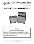
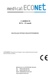
’94 TWIN AMP
p/n 02-4809-000(120V)
SERVICE MANUAL
CONTENTS:
Notices
Specifications
Parts lists:
PCB assembly
Chassis assembly
Cabinet assembly
End item
Schematics/diagrams
Fender Musical Instruments Corp.
7975 North Hayden Road Scottsdale, AZ 85258
’94 TWIN AMP
(This is the model name for warranty claims)
SERVICE MANUAL
JUNE 1995 REV A
TYPE PR266
IMPORTANT NOTICE:
The information contained herein is CONFIDENTIAL and PROPRIETARY to Fender Musical Instruments Corp. It is
disclosed solely for use by qualified technicians for purposes of equipment maintenance and service. It is not to be
disclosed to others without the expressed permission of Fender Musical Instruments Co. All specifications subject to
change without notice.
For warranty repair service, only Fender specified part numbers are to be used. It is recommended they also be used
for post-warranty maintenance and repair.
Parts marked with an asterisk (*) indicate the required use of that specific part. This is necessary for RELIABILITY
and SAFETY requirements. DO NOT USE A SUBSTITUTE!
A coded naming convention is used in the description of certain parts. The codes and what they mean are as follows:
CAPACITOR CODES
HARDWARE CODES
CAP AE
CAP CA
CAP CD
CAP MPF
CAP MY
CAP PFF
BLX
CR
HWH
M
NI
OHP
PB
PHP
PHPS
SMA
SMB
SS
TF
ZI
=
=
=
=
=
=
Aluminum Electrolytic
Ceramic Axial
Ceramic Disk
Metalized Polyester Film
Mylar
Polyester Film/Foil
RESISTOR CODES
RES CC
RES CF
RES FP
RES MF
RES WW
=
=
=
=
=
Carbon Comp
Carbon Film
Flame Proof
Metal Film
Wire Wound
=
=
=
=
=
=
=
=
=
=
=
=
=
=
Black Oxide
Chrome Plated
Hex Washer Head
Machine Screw
Nickel Plated
Oval Head Phillips
Particle Board
Pan Head Phillips
Pan Head Phillips Sems
Sheet Metal "A" Point
Sheet Metal "B" Point
Stainless Steel
Thread Forming
Zinc Plated
’94 TWIN AMP
SPECIFICATIONS
Product Release No.:
PR 266 (This is not a model number)
Part Number:
120V Version :
230V Version :
Power Requirements:
120V Version: 120 volts AC, 60 HZ, 360 watts.
230V Version: 230 volts AC, 50 HZ, 360 watts.
Input Impedance:
Input 1: 1M Ω
Input 2: 136k Ω
Effects Loop:
Pre Reverb.
Nominal Level: +2, -5.5, -13 dbv
Output Impedance: 4.2kΩ maximum
Input Impedance: 130kΩ minimum
Effects Mix Control:
Continuously variable between the signal at the
EFFECTS SEND and EFFECTS RETURN jacks.
Reverb:
Post effects loop.
Preamp Out:
Post reverb, +1.3 dbv nominal level.
Recommended load: 22 k Ω minimum.
Power amp in:
+1.3 dbv sensitivity, 1130kΩ input impedance.
Balanced Line Output:
Derived from the output transformer, fully balanced.
+3 dbv nominal level into 600Ω or greater.
Pin 1 floating, pin 2 (+), pin 3 (-)
Amplifier Load Impedance:
Switch selectable for 4, 8, or 16 Ω.
Power Output:
OUTPUT HIGH setting: 100 watts RMS, 5% THD.
OUTPUT LOW setting: 25 watts RMS, 5% THD.
Speaker Complement:
Two Fender P.N 026488 Special Design 12” 8 ohm
speakers wired in series.
Dimensions:
Height: 20 3/4”
Width: 26 3/8”
Depth: 11 1/2”
Weight: 77 lbs.
21-4809
21-4889
(52.7 cm)
(67 cm)
(29.2 cm)
(35 kg)
Product specifications are subject to change without notice
’94 TWIN AMP
THEORY OF OPERATION
INPUTS
J1 and j2 are high and low sensitivity inputs that feed the first preamp stage (V1A). V1A provides a gain of about 38
for channel 1, and about 49 for channel 2. The gain difference is due to different loading of the plate of V1A. The
signal then couples to relay K1B, which routes it to the channel one or channel two circuitry.
CHANNEL ONE
The ’94 Twin Amp is a direct descendent of classic tube amps like the Twin Reverb and the 410 Bassman. Channel
one is the traditional Fender design which offers the vintage sound as well as contemporary sounds with the use of
switch-selectable Gain and Master Volume controls. It’s like two channels in one. The first stage of Channel One
contains the Treble (R17), Bass (R18) and Mid (R19) tone controls. The signal from the Treble control feeds through
Relay K2B, which routes the signal to either the Clean or Vintage Overdrive section of channel one.
CLEAN
The signal from pin 11 of Relay K2B feeds through the Clean Volume control (R11) to V1B. R12 and C4 provide the
Bright boost feature via a pull switch on the Clean Volume control. V1B provides a gain of about 45. The Clean
channel circuitry terminates at pin 6 of Relay K2A. K2A selects between the output of the Clean or Vintage Drive
circuit.
VINTAGE DRIVE
The signal from Pin 9 of Relay K2B feeds through the Gain control (R8) to the first stage (V2A) of the Vintage Drive
circuitry. V2A provides a gain of about 20, then drives the second gain stage (V2B). V2B provides a gain of about
48; then couples the signal to the vintage drive Volume control (R23), which also contains the select switch for the
Clean/Drive feature. When in the Channel 2 mode, Relay K1A connects the wiper of the Gain control (R8) to ground,
muting the input to the Vintage Drive stage. The Vintage Drive circuit terminates at pin 8 of Relay K2A.
CHANNEL TWO
Channel Two is like owning a second, modern hot-rodded amp with more soaring gain than previously found in a
Fender tube amp. The signal from pin 9 of Relay K1B feeds through the Channel Two Gain control (R25) to the first
(V3A) and then second (V3B) stage of the overdrive circuitry. From V3B, the signal is fed to through the Treble
(R35), Bass (R36), and Mid (R37) tone controls. Finally the signal travels through the channel two Volume control
(R39), which also contains the Channel Select switch. Channel two terminates at pin 9 of Relay K4B. K4B selects
between channels one and two.
EFFECTS LOOP
The selected (Ch-1 or Ch-2) signal from Relay K4B is fed to a Split-Load Phase Inverter (V4A). The output from Pin 1
of V4A follows two paths to Relay K3A. One path travels through one half of the Mix control. The second path
connects directly to K3A. The signal from Pin 3 of V4A drives the Effects Send Jack (J3), and is normalled to the
Effects Return jack (J4). The Effects Level switch provides three signal levels for matching a wide variety of external
signal processing devices. The switch also maintains unity gain between the Send and Return jacks. The signal from
the Effects Return jack feeds V4B, then travels through the other half of the Mix control (R44B), and to Relay K3B.
The dry and wet signals sum together through R54 and R55. Relay K3 is controlled by the Effects Select switch in
the Both position, K3 will be in the Normally Closed position. Any signal available at the Effects Return jack will pass,
whether in Ch-1 or Ch-2. The Mix control will be active. With the Effects Select switch in the Ch-1 position, the
Effects Return will be active while the amp is in the Ch-1 mode. When the amp is switched to the Ch-2 mode, the
control voltage from U2B will energize relay K3, K3A will toggle, bypassing one half of the Mix control (R44A), and
K3B will break the connection from the Effects Return. Therefore the Effects Return will be active only for the channle
that is selected by the Effects Select switch.
REVERB
The signals from Relays K3A & K3B sum through R54&R55, then split to feed the Reverb Drive circuit and the
summing amp for the Wet and Dry signal. V5 (12AT7) and T1 make up the standard Reverb Drive circuit. The
’94 TWIN AMP
THEORY OF OPERATION(CONT)
Reverb return circuit uses JFET Q1. Without a footswitch connected to the footswitch jack, diode CR17 enables the
reverb to function. V6A amplifies the reverb return signal. Note that V6A should provide a minimum gain of 49. The
output from V6A drives the Reverb control (R62), then sums with the dry signal through R63.
V6B feeds the Cathode Follower V7B, which drives the Preamp Out jack. The signal is normalled to the Power Amp
in jack and then feeds V7A. V7A contains the Presence control, accepts feed back from the output and feeds the
Phase Inverter V8.
OUTPUT SECTION
The output tubes (V9, V10,V11, V12, 5881/6L6WGC) are arranged in a push-pull configuration that will produce
100watts into a 4, 8, or 16 Ω load. The Impedance Selector (S10) will switch between the respective taps of the
output transformer secondary. CR1&CR4 are flyback protection diodes that prevent the output transformer from an
over voltage condition. This can occur when the output transformer experiences an open load. A separate
secondary winding drives an XLR jack (J13), which provides a balanced line out with a floating ground pin (pin1).
This can be used to drive a slave amp and additional speaker cabinets. It can also be used as a send to a mixing
console. However to get a useful sound, the signal should be pre-equalized before the console input. A low-pass
filter set a 5 to 6 kHz with a minimum 18 db per octave slope works well.
BIAS
The Bias is set by measuring the voltage drop across the Flame Proof 1 Ω resistors R89 & R90. If the voltage drop
reads 80mV, then the current through the resistors will be 80mA (E/R=1) = (80mV divided by 1 Ω = 80mA). CR2 & 3
are protection diodes for R89 & R90. If an output tube shorts, the fault current will shunt through the diodes instead of
R89 & R90.
BIAS ADJUSTMENT
The Bias Adjust and Balance Adjust controls, along with the Bias and Balance test points are located on the rear
panel for easy access. Allow the amplifier to warm up for at least 2-3 minutes with the Output switch set to High, and
the Standby switch in the On position. With a digital voltmeter set to its most sensitive DC voltage scale; connect the
test probes to the test points (J11 & J12) labeled “Bias”. Adjust the Output Bias Adjust control (R94) to read .08 VDC
(80mVDC). This will Bias V9 &V10. Now connect the test probes across the “Balance” test points (J10 & J11). The
meter is now referenced to the 80mVDC instead of ground. Adjust the Output Balance Adjust control to obtain 0VDC.
This precisely matches V11 & V12 to V9 & V10. For optimum sonic performances, set Bias to 80mVDC, then set
Balance.
For optimum sonic performance with increased tube life, set Bias to 60mVDC, then set Balance.
For optimum tube life, set Bias to 40mVDC, then set Balance.
Note: If a bias measurement of 40mVDC cannot be obtained, it may be time to replace the output tubes.
CHANNEL/REVERB SWITCHING
A 27.5VAC signal is tapped off from the Brown secondary of the power transformer. This signal is presented to the
Footswitch jack. By rectifying the positive or negative half of the waveform, a DC control voltage is created. This
voltage is used to control several opamp comparator circuits.
TROUBLESHOOTING TIP
Most channel switching problems will probably be related to intermittent or sticky relays. However troubleshooting the
switching circuitry is easy. All test point voltages are on the schematic. First verify the reference voltage at the
comparator. The reference voltage is applied to the non-inverting input of the opamp. Then measure the output of
the comparator. If it doesn’t toggle properly, check the control voltage. If the control voltage is not correct, hang a
scope probe on the footswitch jack. Look at the AC waveform, activate the channel select switches, and look for the
rectified waveform. The Reverb is switched by rectifying the negative side of the waveform. The Gain Select and
Channel Select are switched by rectifying the positive side of the waveform at two different voltage levels. Diode
CR16 and Zener CR18 set the two voltage levels.
POWER LEVEL SWITCHING
Via the output switch (S9) the output power of the amplifier can be switched between 25 and 100 watts. S9A selects between the
center tap and full winding of the high voltage secondary of the power transformer. This causes the B+ and Z supplies to
’94 TWIN AMP
THEORY OF OPERATION(CONT)
switch from +454Vdc to +230Vdc. This voltage change only affects the four output tubes. The high voltage supplies for the
preamp tubes are tapped off prior to the output switch (S9). When switching the high voltages at the power tubes, the negative
Bias voltage must also be switched. The Bias supply is derived through a voltage doubler from the Brown secondary of the
power transformer. S9B determines the path of the Bias current. The low power path is through R97 (100K), and the high power
path is through R98 (18K) and R97 (100K) in parallel. R96 (82K) sets up the voltage divider that feeds the Bias and Balance
controls (-52Vdc High, -21 Vdc Low).
Note: It is recommended that the amplifier be in the Stand-by mode before switching the High/Low Output switch.
LOW POWER OPTION
The ’94 Twin Amp can be run with only two output tubes instead of four. This is done by removing the inner two 5881/6l6wgc
tubes. The Impedance Selector switch must be set to one-half the total speaker load. The rule is ---half the tubes---half the
impedance. Therefore when using the internal two speakers (16 Ω load), the Impedance Selector switch must be set to 8 Ω. This
will produce 60 watts RMS in the Output High setting, and 15 watts RMS in the Output Low setting.
PARTS LIST
NOTE: SHADED ITEMS ARE FOR REFERENCE ONLY
PART #
PRINTED CIRCUIT BOARD ASSEMBLY
DESCRIPTION
REFERENCE DESIGNATION
1
1
1
7
4
4
4
1
2
2
2
2
1
2
1
2
1
1
2
3
2
7
2
2
5
2
1
1
1
1
2
1
4
048973
048972
038691
009512
024819
036954
024820
028471
031040
013638
028482
039362
025982
020917
025777
011435
017620
039265
026202
025962
027275
024833
024835
024853
024854
027281
027286
024876
049028
047781
041510
037600
037597
CABLE RIBBON 9 CKT 15 ¾ IN
CABLE RIBBON 9 CKT 9 ¾ IN
CAP AE AX 4.7 UF 50V
CAP AE AX 22 UF 25V 20%
CAP AE AX 22UF 500V
CAP AE RDL 22UF 63V 20%
CAP AE AX 47UF 350V
CAP AE RDL 47UF 50V 20%
CAP AE RDL 100UF 100V 20%
CAP AE AX 220UF 285V
CAP AE RDL 220UF 50V 20%
CAP AE RDL 1000UF 35V LOPROFIL
CAP CD 68PF 1000V 10%
CAPCD 250 PF 1000V 10%
CAP CD 470PF 1000V 10%
CAP CD 680PF 1000V 10%
CAP CD 1500PF 1000V 10%
CAP CA 2200PF 100V
CAP PFF .0022UF 600V
CAP PFF .0047UF 400V
CAP MPF .068 UF 100V
CAP MPF RDL .022UF 400V 10%
CAP MPF RDL .022UF 630V 10%
CAP MPF RDL .1UF 250V 10%
CAP MPF RDL .1UF 400V 10%
CAP MPF .22UF 63V
CAP MPF .47UF 63V
CAP MPF RDL .68UF 250V 10%
CONTROL POT 1M 2B W/DPDT
CONTROL SNAPIN 1K 15C
CONTROL SNAPIN 25K B
CONTROL SNAPIN 100K B
CONTROL SNAPIN 250K 30A
P3A
P2A
C35
C1,5,11,24,28,53,61
C22,42,43,44
C36,37,59,62
C40,41,51,52
C60
C45,50
C38,39
C46, 49
C47,48
C4
C6, 17
C25
C13,27
C31
C30
C10,14
C12,29,65
C57,58
C3,8,9,16,18,26,63
C32,33
C23,34
C2,7,15,19,21
C55,56
C54
C20
R39
(CHANNEL 2 VOLUME)
R82
(PRESENCE)
R19, 37
(CHANNELS 1&2 MID)
R62
(REVERB)
1
047780
CONTROL SNAPIN 250 K 30A
R23
QTY
R17,18,35,36
TREBLE,BASS)
(CHANNELS 1&2
(CHANNEL 1 DRIVE VOLUME)
’94 TWIN AMP
QTY
1
1
2
2
11
14
2
1
2
1
8
7
1
7
1
4
14
1
2
2
1
1
1
1
9
6
2
1
1
1
1
1
1
1
1
1
1
2
2
1
3
9
1
1
1
PART #
PRINTED CIRCUIT BOARD ASSEMBLY (CONT)
DESCRIPTION
REFERENCE DESIGNATION
041511
041512
037596
026133
026730
006260
031729
028990
024995
024996
024997
028955
025058
025059
028016
025065
025069
025077
025084
041741
025941
026549
026493
031065
025116
025117
033095
037354
041739
027349
041738
027350
027352
027353
041277
041740
041737
036924
029047
041742
038652
026001
028503
041261
014689
CONTROL SNAPIN 250K B DUAL
CONTROL SNAPIN 1M 30A
CONTROL SNAPIN 1 MEG J TAPER
CONTROL TRIM 25K LIN
DIODE 1N4006 800V
DIODE 1N4448 SIGNAL
DIODE ZEN 1N5231B .5W 5.1V 5%
RES CF ¼W 5% 51K
RES CF ¼W 5% 68K
RES CF ¼W 5% 82K
RES CF ¼W 5% 100K
RES CF ¼W 5% 130K
RES CF ¼W 5% 180K
RES CF ¼W 5% 220K
RES CF ¼W 5% 300K
RES CF ¼W 5% 470K
RES CF ¼W 5% 1M
RES CF ¼W 5% 3.3m
RES CF ¼W 5% 10M
RES MOX FP ½W 5% 47Ω
RES CF ½W 5% 560Ω
RES CF ½W 5% 1.5K
RES CF ½W 5% 2.7K
RES CF ½W 5% 91K
RES CF ½W 5% 100K
RES CF ½W 5% 220K
RES MOX FP 1W 5% 1Ω
RES FILM 1W 5% 4.7K
RES MOX FP 1W 5% 6.8K
RES FILM 1W 5% 10K
RES CF 1W 5% 15K
RES FILM 1W 5% 22K
RES FILM 1W 5% 91K
RES FILM 1W 5% 100K
RES CF 2W 5% 820Ω
RES MOX FP 2W 5% 4.7K
RES CF 2W 5% 33K
RES WW BT 5W 10% 1K
RES WW BT 7W 10% 270Ω
RES WW VT 7W 10% 10K
SWITCH SLIDE 4P3T
TERMINAL EYELET W/ LUG
THERMISTOR 10 Ω 5A C60-11
VOLT REF LM4040DCZ-10V TO-92
XSTR N-CH JFET J111 TO-92
R44
(MIX)
R11 (CHANNEL 1 CLEAN VOLUME)
R8,25
(CHANNELS 1,2 GAIN)
R92,94
(BIAS/BALANCE ADJUST)
CR2,3,5-11, 14, 15
CR16,17,19,20,22-30,32
CR18, 31
R50
R1,2
R96
R16,24,34,59,70,71,97,153
R51,54,55,93,95,142,147
R49
R22,26,29,32,58,64,141
R125
R63,76,77,129
R3,6,7,40,56,118,121,123,127,128,135,138,156,157
R65
R12,38
R108,109
R57
R134
R120
R146
R5,10,15,21,27,30,61,67,140
R99-102,110,111
R89,90
R80
R104
R42
R43
R79
R73
R72
R112
R103
R53
R91,154
R106,107
R105
S4-6
1
TH1
U1
Q1
CHASSIS ASSEMBLY
QTY
4
1
2
15
15
1
2
1
3
5
8
PART #
DESCRIPTION
REFERENCE DESIGNATION
016473
028684
026521
028937
025936
026472
036570
049976
023531
013341
023598
SCRW M 8-32X1/2 PHP ZI
SCRW SMB 6X3/8 PH PHS BLX
SCRW SMB RX3/8 RH PHS BLK
SCRW TF 6-32X5/8 PHPZI TAPTYT
STANDOFF NYLON PCB SNAPIN 3/8”
SWITCH SLIDE DPTT
SWITCH TOGGLE DPST W/ NUTS
SWITCH TOGGLE DPST W/ LEADS
TUBE 12AT7
TUBE 7025/12AX7A SOVIET MADE
TUBE SHIELD
(OUTPUT TRANSFORMER MOUNT)
(@J6, REVERB RCA JACKS)
(@ J13, BALANCED LINE OUT)
(PCB TO CHASSIS MOUNT)
(PCB TO CHASSIS MOUNT)
S10
(IMPEDANCE SELECT)
S7,8
(POWER, STANDBY)
S9
(OUTPUT HIGH,LOW)
VR4,5,8
V1,2,3,6,7
(@V1,2,3,4,5,6,7,8)
’94 TWIN AMP
QTY
4
8
4
2
2
3
8
3
1
1
1
1
1
QTY
1
2
2
1
1
3
1
1
8
3
3
3
PART #
023580
023606
039214
9904300100
026564
027520
022319
031153
026401
047776
049052
026478
037099
CHASSIS ASSEMBLY (CONT)
DESCRIPTION
REFERENCE DESIGNATION
TUBE SOCKET 8 PIN
TUBE SOCKET 9 PIN
TUBE VACUUM 5881/6L6WGC
WASHER LCK INTL 3/5X.681X.032
WSHR FLAT .284X1/2ZI
WSHR FLAT .380X.630 FIBER
WSHR FLAT ¼X9/16 NI
WSHR FLAT 3/8X.614 NI
WSHR SHLDR FIBER 3/8X5/8
XFMR 94 TWIN 120V
XFMR PWR 94 TWIN EXPORT
XFMR OUTPUT 100W 4,8,16 Ω
XFMR REVERB VIBROVERB
XV9,10,11,12
XV1,2,3,4,5,6,7,8
V9,10,11,12
(@J14,16)
(@R92,94 BIAS/BALANCE POTS)
(@J14,15,16)
(POWER TRANSFORMER MOUNT)
(@J14,15,16 SPKR OUTPUT JACKS)
(@J15)
T3 (120V DOMESTIC ONLY)
T3 (100V,115V,230V.240V)
T2
T1
PART #
FOOTSWITCH ASSEMBLY
DESCRIPTION
REFERENCE DESIGNATION
028895
006260
031017
047800
037036
031871
031647
024952
028889
041527
028714
031899
CABLE ASSY FTSW RT ANG 12’
DIODE 1N4448/1N914B SIGNAL
DIODE ZEN 1N5223B 2.7 V 5%
FTSW ASSY 3BTN GAIN/CH/REV
JACK PHONE PCB MONO CA PREMIUM
LED BI-COLOR 5MMX5MM
NUT HEX 12MMX1MM NI
RES CF 1/4W 5% 100Ω
SCRW SMB 6X1/4 PHP
SPACER RND NYL .680X.250X.147
SWITCH PUSH SPDT
WSHR NYL .485X.775X.150TK
(FOOTSWITCH CABLE)
CR1,3
CR2,4
(COMPLETE FOOTSWITCH)
J1
LD1,2,3
(@J1)
R1
(END CAP MOUNT)
(LD1,2,3)
S1,2,3
(@S1,2,3)
MISCELLANEOUS
QTY
1
1
PART #
DESCRIPTION
047775
047768
MANUAL OWNERS ’94 TWIN AMP
SCHEM REDU W/ SRV ’94 TWIN AMP
REFERENCE DESIGNATION
’94 TWIN AMP
BLOCK DIAGRAM
’94 TWIN AMP
SERVICE MANUAL
ADDENDUM
This addendum contains important modification and revision information including parts and revision “C” schematics.
Please attach to the existing service manual for the ’94 Twin Amp.
CONTENTS:
Notices
Description of changes
Parts list
Schematics/diagrams
Fender Musical Instruments Corp. 7975 North Hayden Road Scottsdale, AZ 85258
’94 TWIN AMP
ADDENDUM
(This is the model name for warranty claims)
SERVICE MANUAL
ADDENDUM
MAY 1996
TYPE PR 266
IMPORTANT NOTICE:
The information contained herein is CONFIDENTIAL and PROPRIETARY to Fender Musical Instruments Corp. It is
disclosed solely for use by qualified technicians for purposes of equipment maintenance and service. It is not to be
disclosed to others without the expressed permission of Fender Musical Instruments Co. All specifications subject to
change without notice.
For warranty repair service, only Fender specified part numbers are to be used. It is recommended they also be used
for post-warranty maintenance and repair.
Parts marked with an asterisk (*) indicate the required use of that specific part. This is necessary for RELIABILITY
and SAFETY requirements. DO NOT USE A SUBSTITUTE!
A coded naming convention is used in the description of certain parts. The codes and what they mean are as follows:
CAPACITOR CODES
HARDWARE CODES
CAP AE
CAP CA
CAP CD
CAP MPF
CAP MY
CAP PFF
BLX
CR
HWH
M
NI
OHP
PB
PHP
PHPS
SMA
SMB
SS
TF
ZI
=
=
=
=
=
=
Aluminum Electrolytic
Ceramic Axial
Ceramic Disk
Metalized Polyester Film
Mylar
Polyester Film/Foil
RESISTOR CODES
RES CC
RES CF
RES FP
RES MF
RES WW
=
=
=
=
=
Carbon Comp
Carbon Film
Flame Proof
Metal Film
Wire Wound
=
=
=
=
=
=
=
=
=
=
=
=
=
=
Black Oxide
Chrome Plated
Hex Washer Head
Machine Screw
Nickel Plated
Oval Head Phillips
Particle Board
Pan Head Phillips
Pan Head Phillips Sems
Sheet Metal "A" Point
Sheet Metal "B" Point
Stainless Steel
Thread Forming
Zinc Plated
’94 TWIN AMP
ADDENDUM
DESCRIPTION OF CHANGES
All of the following modifications are present on revision “E” printed circuit boards. Some of the
other modifications appear on earlier revision PCBs.
The PCB revision level is located on the solder side of the centermost PCB, near the orange wire
and filter capacitor C40.
Reason For Changes:
Compliance with Safety Regulatory Agencies:
Added “Crowbar” protection circuit (CR33 – 38) to the screen (Z) supply
capacitors (C40, 41). The crowbar circuit is present on Revision D & E
printed circuit boards.
Do not attempt the above modification to earlier revision PCBs.
Added RF emissions suppression capacitor (C64, P/N 025995) across the high
voltage transformer secondary, prior to the full-wave bridge rectifier circuit.
Performance modifications:
Added CR32 and changed R124 and R134 to ensure that Relays K1, K2, and K3
drop out when de-energized. (See zone 7B on Rev C schematic).
Refer to Tech Note TN95-4
Upgraded the HIGH/LOW OUTPUT power switch.
Refer to Tech Note TN96-3
Changed the Reverb muting circuit to eliminate noise in the reverb recovery circuit
caused by poor power line conditions. Change R59 from 100k to 1.8k, add Q2
(JFET) and R155 (1.8k). (See zone 4C on rev C schematic).
Refer to Tech Note TN96-5
Attached is a Revision C schematic/service diagram.
’94 TWIN AMP
ADDENDUM
PARTS LIST REVISIONS
PRINTED CIRCUIT BOARD ASSEMBLY
QTY PART #
5
2
1
15
14
2
3
4
1
3
1
1
2
024819
024820
025995
026730
006260
041811
047234
024962
026549
025117
047768
049976
014689
DESCRIPTION
CAP AE AX 22uF 500V
CAP AE AX 47uF 350V
CAP CD
8200PF 1000V 20%
DIODE 1N4006 800V
DIODE 1N4448 SIGNAL
DIODE ZEN 1N5368B 47V 5W 5%
RES CF
1/6W
5%
1.8k
RES CF
1/4W
5%
560Ω
RES CF
1/2W
5%
1.5k
RES CF
1/2W
5%
220k
SCHEM REDU W/SERV ’94 TWIN AMP
SWITCH TOGGLE DPST DC W/NUT
XSTR N-CH JFET J111 TO-92
REFERENCE DESIGNATION
C22,42,43,44,51
C40,41
C64
CR2,3,5-11,14,15,34-37
CR16,17,19,20,22-30,32
CR33,38
R59,117,155
R41,52,124,137
R134
R99,100,101
(REVISION “C”)
S9 (REFER TO TECH NOTE TN96-3)
Q1,2
TECH NOTES
Fender Musical Instruments Corp.
7975 North Hayden Road Scottsdale, Arizona 85258
TECH NOTE #
TN96 - 3
ISSUE DATE:
ISSUED BY:
PAGE:
March, 1996
C. Colaço
1 of 2
PRODUCT(S) AFFECTED:
'94 TWIN AMP
(All Serial numbers prior to LO-673648 should require this modification)
SYMPTOMS:
Overheating of power tubes when in the LOW OUTPUT power mode.
Unit appears to be locked into the HIGH OUTPUT power mode.
CONDITION:
Arcing between switch contacts in the high voltage leg of the HIGH/LOW OUTPUT
power switch (S9). The arcing occurs only when the HIGH/LOW OUTPUT switch is
operated while the amplifier is in the fully on mode (NOT IN STANDBY). This may
cause burning, pitting, and eventual welding together of the switch contacts. Therefore
when the amplifier is switched to the LOW power mode, the high voltages at the output
tubes remain high, but the Bias voltage drops. The result is a severely under Biased
output stage that quickly overheats.
REQUIRED ACTION:
A new style switch has been specified for this application.
Determine if the old style switch is installed in the unit. The old style switch is identical
to the Power and Standby switches. If the old style is present, order P/N 049976
SWITCH TOGGLE DPST DC W/NUT. The new style switch will have a pair of White &
Black leads as opposed to Faston lugs. The leads must be soldered directly to the
power supply PCB. This is to comply with safety regulatory agencies (U.L.,C.S.A.).
DO NOT SPLICE THE SWITCH LEADS WITH THE EXISTING JUMPER WIRES.
TECH NOTE #
TN96 - 3
PAGE:
2 of 2
To gain access to the solder side of the PCB, disconnect the Black wires from CP1 &
CP2. Disconnect the wires at the Stand-by switch. This will allow the PCB to be tilted up
from the rear.
Remove the old style HIGH/LOW OUTPUT switch & wires. Note the location where the
Blue and Brown wires solder to the PCB.
Early revision (A-D) PCB's are silk-screened "TO OUTPUT SWITCH", "BLU" & "BN'.
Solder the pair of White switch leads to the two points labeled "BLU". Solder the pair of
Black switch leads to the two points labeled "BN". Revision "E" PCB's are silk-screened
"TO OUTPUT SWITCH", "WHT" & "BLK". White leads to "WHT", Black leads to "BLK".
Re-install the PCB. Verify proper switching of the B+ and negative Bias voltages.
WARRANTY CLAIM INSTRUCTIONS:
The above modification should be performed on any '94 Twin Amp requiring service in
or out of warranty. For proper labor reimbursement, please indicate the Tech Note
Number TN96-3 in the Authorization Code Box (Box # 12) on the Warranty
Reimbursement Form. Labor reimbursement = 1 Hour.