1
Service
Manual
Technical Reference and Troubleshooting Guide
BMW334 Warming Cabinet
December 1996, rev. 0.9
1333 East 179th St.
Cleveland, Ohio 441 10
Phone (216) 481 -4900
Cleveland WARRANTY AND
LIMITED EXTENDED WARRANTY COVERAGE
LIMITED WARRANTY
Cleveland Range products are warranted to the original purchaser to be free from defects in material and workmanship under normal use and service for the standard warranty period.
I
Cleveland Range agrees to repair or replace, at its option, f.0.b. factory, any part which proves to be defective due
to defects in material or workmanshio durino the warrantv. orovidino the eouioment has been unaltered and has been
PROPERLY INSTALLED, MAINTAINED, AND~PERATEDINACCORDANCEWITH THE CLEVELAND RANGE OWNER'S
MANUAL.
1
CLEVELAND RANGE agrees to pay any FACTORY AUTHORIZED EQUIPMENT SERVICE AGENCY (within the continental United States. Hawaii, and Canada) for reasonable labor required to repair or replace, at our option, f.0.b. factory,
any part which proves to be defective due to defects in material or workmanship, during the labor warranty period. This
warranty includes travel time not to exceed two hours and mileage not to exceed 50 miles (100 miles round-trip), but
does not include post start-up, tightening loose fittings, minor adjustments, maintenance, cleaning or descaling.
l
The standard labor warranty allows factory payment of reasonable labor required to repair or replace such defective parts. Cleveland Range will not reimburse the expense of labor required for the repair or replacement of parts
after the standard warranty period, unless an Extended Warranty Contract has been purchased to cover the equipment
for the balance of the warranty period from the data of equipment installation, start-up, or demonstration.
PROPER INSTALLATION IS THE RESPONSIBILITY OF THE DEALER, THE OWNER-USER, OR INSTALLING CONTRACTOR, AND IS NOT COVERED BY THlS WARRANTY. Many local codes exist, and it is the responsibility of the
owner and installer to comply with these codes. Cleveland Range equipment is built to comply with applicable standards for manufacturers, including UL, AG.A. NSF, ASMVNU. Bd., CSA. CGA, ETL, and others.
BOILER (SteamGenerator) MAINTENANCE IS THE RESPONSIBILITY OF THE OWNER-USER. AN0 IS NOT COVERED BY THlS WARRANTY. The use of good qualty feed water is the responsibility of the Owner-User (see Water
Quality Requirements below). THE USE OF POOR QUALITY FEED WATER WILL VOID EQUIPMENTWARRANTIES.
Boiler maintenance supplies, including boiler hand gaskets, are not wananted beyond the first 90 days after the
date the equipment is placed into service if no preventive maintenance records are available showing descaling
every 90-120 days.
WATER
QUALITY
REQUIREMENTS
Total Dissolved solids
Total Alkalinty
Silica
Free Chlorine
Chlorides
pH factor (acidity)
less than 60 parts per million
less than 20 parts per million
less than 13 parts per million
less than 0.5 parts per million
less than 25 parts per million
neutral, 2 1.0 pH
The foregoing shall constitute the sole and exclusive remedy of original purchaser and the full liability of Cleveland Range for any breach of warranty.THE FOREGOING IS EXCLUSIVE AND IN LIEU OF ALL OTHER WARRANTIES,
WHETHER WRITEN. ORAL, OR IMPLIED, INCLUDING ANY WARRANW OF PERFORMANCE. MERCHANTABILITY,
OR FITNESS FOR PURPOSE, AND SUPERSEDES AND EXCLUDES ANY ORAL WARRANTIES OR REPRESENTATIONS,
OR WRlllEN WARRANTIES OR REPRESENTATIONS, NOT EXPRESSLY DESIGNATED IN WRITING AS A WARRANTY OR 'GUARANTEE" OF CLEVELAND RANGE MADE OR IMPLIED IN ANY MANUAL. LITERATURE, AOVERTISING BROCHURE OR OTHER MATERIALS.
Cleveland Range's liability on any claim of any kind, including negligence. with respect to the goods or sewices
covered hereunder, shall in no case exceed the price of the goods or services, or part thereof, which gives rise to the
claim. IN NO EVENT SHALL CLEVELAND RANGE BE LIABLE FOR SPECIAL. INCIDENTAL, OR CONSEQUENTIAL
DAMAGES, OR ANY DAMAGES IN THE NATURE OF PENALTIES.
LD
Cn
-B
m
LIMITED EXTENDED WARRANTY COVERAGE
The purchase of a Limited Extended Warranty Contract extends the standard warranty coverage to the purchased
~eriodof time (one to four veanl from the date of installation. start-uo. or demonstration. whichever is sooner.
g
0
1
II
II
Contents
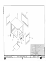
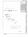
Service Assembly Drawings
WARM2 - Frame and Sheeting
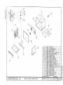
WARM3 - Interior Cavity and Components
WARM4 - Control Panel and Components
General Overview ........................................... 1
Electrical Circuit Overview ............................. 2
Temperature Controller ................................ --- 3
Troubleshooting Procedures ........................... 5
BMW334 Service Manual
Cleveland Range
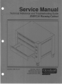
BMW334 Warming Cabinet
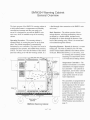
General Overview
The basic purpose of the BMW334 warming cabinet is
to hold cooked meats in a temperature and humicbty
controlled environment until they are ready to be
served. It is designed for use with the BMR32 rotisserie oven, which is installed on top of the warming
cabinet.
Operating Procedure - The warming cabinet is
operated simply by turning the power on at the front
panel. The cabinet temperature is automatically
maintained by two controllers. The water level must be
monitored by the operator, and refilled when necessary.
(NOTE:The drain valve near the bottom of the control
panel has nothing to do with the warming cabinet. It is
a feed-through drain connection to the BMR32 rotissene oven.)
Basic Functions - The cabinet consists of three
storage drawers, with large perforations, that are
enveloped by a double-walled, insulated cawty.
Moistened air is drawn through the drawers to the
back of the warming cavity, where it is warmed and
recirculated through the drawers.
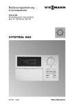
Operating Elements - Beneath the drawers is a water
heating pan. The water is heated by two 500 watt
surface-contact heaters adhered to the bottom surface
of the pan. Behind the drawers, in a sub-cam, is an
air warming and circulating system
consisting of a small blower and a
1250 watt electric heating element.
Temperature Controllers - The
cabinet's environment is accurately
controlled by two digital temperature cantrollers - one controls air
temperature, and the other controls
water temperature. Two thermocouple probes sense the air and
water temperatures.
>/--
Water Heating
Elements
BMW334 Warming Cabinet
The controllers are programtned at
the fhctory to the desired air and
water temperatures for the typical
chicken product. Once these
controllers have been programmed,
no operator intervention is required. The controllers &splay the
actual temperatures of the air and
water. The setpoint temperatures
can be displayed by pressing the
TEMP buttons (see procedure on
page 3)-
BMW334 Warrn~ngCab~net
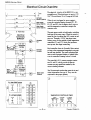
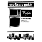
Electrical Circuit Overview
The electrical circuitry of the BMW334 is very
straightforward. Electrical power is input at 120
VAC. The unit draws 20 to 30 amps at full load.
Air Heater
...
--
HZ
H3
.
St Power Smtch
5
Electrical
Schematic
BMW334
Element (1250 W.) When the unit is plugged in, power appears
across the contactorheating elements (R1, R2,
Water Heater
Element (650 W.) HI, H2, and H3), but the heaters don't wme on
Water Heater
until the temperature wntrollers energize the
Element (650 W.) wntactor wils.
.
I
Z<
Cvculabon
Fan
C1 - hr
-
-
11
"
,0;
Q
Ar Heatw
Contactor
The main power switch is double-pole, switching
both legs of the power input. When the switch is
turned on, the circulation fan (MI) wmes on and
stays on. Through a 24VAC stepdown transformer, power is also applied to bath temperature
controllers (C 1 and C2), which first perform a
start-up test, then begin controlling.
Each controller closes its Normally Open contact
as long as the programmed temperature set point
has not been reached. The small indicating light
next to each front-panel display is lighted whenever the controller's heating contact is closed.
The controller's N.O. wntacts energize wntactors R1 and R2, which provide the heavier
current-carrying capabilities needed by the
resistive heating elements.
The Thermocouple probes that sense the air and
water temperatures are type K. They must be
wnnected in the proper polarity
R2 - Water Heater Contactor
111
at
A
uo
mil
0
@
R1 -Air Heater Contactor
@
t ill1
mil
A
0
UII@
I
I
TEMPERATURE COMROLLER TIMER
TYPE K
T H R O E
RED
YE1
18 - 28 VAC
A
. ...
-1
(d
YFRMR
3 VA
(
1
r+-, j
-
12 240 VAC
I AMP W.
N.O.
Cleveland Range Inc.
-
BMW334
Setvtce Manual
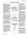
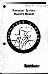
Temperature Controller
The BMW344 uses two identical
digital temperature controllers to
regulate air and water temperatures.
Temperature is controlled by turning
the heating elements on and off.
There is an adjustable upper and
lower deadband (hysteresis). The
regulation ("setpoint") temperature
can be set in one degree increments.
Temperature display can be in either
Fahrenheit or Centigrade,
unfigurable from the front panel.
' h e "Heat On" indicator will light
whenever the Heater Output relay is
energ&.
CHANGING TEMP
ATURE SCALES
\
AIR
I
To make any changes to the
controller's program, press and hold
the PROG button for 2 seconds. This
will cause the controller to leave the
"run" mode and enter the "program"
mode.
NOTE: When a controller is in the
program mode, the heater output is
forced open, and heating is inactive. When in the program mode, if
the controller senses no operator
!I
activity after 2 seconds, the
display will begm flashing. This is
an indication that no heating is
taking place and the operator must
press the PROG button to resume
nonnal operation.
Cooking Specialists
Press and hold both the UP and
DOWN buttons for more than 112
second to toggle betwem the F and
C temperature scales. (The temperature scale can be changed in either
the program mode or the run mode.
All parameters will be converted
automatically.)
CHANGING THE SETPOINT TEMPERATURE
1 TEMPERATURE DlSPLAY 1
During operation, the displays show
the actual air and water temperatures.
To view the setpoint temperature (the
temperature being controlled to),
press and hold the TEMP button.
Release the TEMP button when done.
I
WATER
DO NOT OPERATE
WITHOUT WATER
IN PAN
The first display in the program
mode shows alternately "SET"
"PNT", followed by the setpoint
temperature, in F or C. To change
the setpoint, press the UP or DOWN
arrow button - holding the arrow
button down will cause an automatic
repeat after one second. When done
viewing or changing the setpomt,
press the PROG button again to
resume normal operation. ' h e new
setpoint temperature is stored in the
controller, and it will begin to
regulate to the new temperature.
To view or set other functions
while in the program mode,
press "TEMPIADV" to scroll to
another function. (On some
controllers, the button is labelled
only "TEMP").
SETTING THE DEADBAND (HYSTERESIS)
1
The temperature at which the Heater
Output will turn on or off can be
offset from the setpoint by up to
plus or minus 20 deg. F (1 1 C).
(Refer to the settings table on the
next page.) This hysteresis is set at
>> 3 cc
BMW334 Warming Cabinet
the factory. Do not change this setting. If for some
reason this setting has been changed, use the following
procedure to retum it to the factory setting:
Press and hold the PROG button.
Press the TEMPIADV button until the words
"dead" "band" "ON" appear, Mowed by a
number. This is the number of degrees that the
controller will add to the setpoint value before it
turns on the heater output. (A minus number
indicates that the heater will be turned on that
many degrees below the setpoint.)
Press the UP or DOWN button to change the ON
hysteresis value.
Next, press the TEMPIADV button until "OFF"
and andher number appears. This is the turn-off
hysteresis value.
Again, use the UP or DOWN arrow button to
change the value.
Press the PROG button to return to the run mode
of operation.
1
1 ERROR MESSAGES
"PROB" - If the controller's thermocouple probe is
open, the controller displays "Prob" and all controller
fundions will be turned off until the probe is replaced
or reumnected.
"FAIL" -When the cabinet is first turned on, the
wntrollers perform a self-test. If the test determines
that the controller's memory has failed to store the
necessary settings, the display will flash "FAIL"
continuously and all functions will be disabled. The
cootroller will assume the Mowing settings: regulation temperature set to minimum, the offset value set to
zero, the turn-off hysteresis set to zero, and the t u r n a
hysteresis will be set to one degree below the turn-off
hysteresis value. If the controller fails the memory test
and displays the "FAIL" message, turn off power
momentarily and turn it back on. If repowering the unit
corrects the memory problem, reprogram per the
parameters below and let the unit operate. If not,
service will be necessary.
NOTE: Setting the turn-off hysteresis value lower than
or equal to the t u m a value is not permitted. The
controller will limit the t u m a value to one-half
d e p lower than the turn-off value.
FACTORY SE-TTINGS
- TEMPERATURE CONTROLLERS
/
Air Temperature Controller
Setpoint:
Turn-On Hysteresis:
Turn-Off Hysteresis:
Probe Calibration Offset:
1
180 degrees F.
0 degree F.
1 degree F.
0 degree F.
Water Temperature controller ]
Set~oint:150 degrees F.
Turn-On ~ ~ s t h e s i s0:degree F.
Turn-Off Hysteresis: 1 degree F.
Probe Calibration Offset: 0 degree F.
Cleveland Range Inc.
BMW334 Service Manual
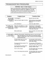
1 TROUBLESHOOTING PROCEDURES
WARNING: Injury or Death Hazard
Death, severe electrical shock or equipment damage can result from touchlng
any component lnslde the unb when the unb 1s plugged lnto a l ~ v eoutlet
Whenposs~ble,unplug the unlt before removing the access panel prlor to
troubleshoonng lfzt 1s necessary to troubleshoot w ~ t power
h
apphed, use
extreme c a n o n dunng tesnng w ~ t hthe access cover removed
1
~vmotom
Probable Cause
UNIT APPEARS Unit not plugged in
"DEAD"WHEN
POWER SWITCH Branch circuit breaker tripped or fuse blown
TURNED ON
Power switch defective
NO HEATING AT ALL, Main power switch defective; or, wiring
AIR OR WATER - between power switch and both controlBOTH CONTROLLERS lers f a u b
APPEAR DEAD
Both controllers faulty
AIR AND/OR WATER
NOT HEATING
BUT HEAT LIGHT IS
ON
Cooking Specklists
Corrective Action
1
Plug power cord into live outlet
Determine and correct cause of tripped
breaker or blown fuse;reset breaker or
replace fuse
Check switch; replace if defective
Check that power is being properly
switched; replace switch if defective;
wiring from switch to both controllers may
be bad; check wiring, repair.
Remove controllers, test on bench; replace
if necessary
Discussion: If the controller is calling for heat, but the air or water is not being
heated, the heating power circuit is faulty. First check that the required
contacts are closing; if they are OK, turn off power and check the heating
elements and the wiring.
The Heater Output contact (N.O.) on the
controller C 1 (or C2) is failed open
If yon can measure 12OVAC across the
contacts, they are open when they should be
closed, replace controller
The contact(s) of the heater contactor R1 (or
R2) are failed open
If you can measure 120VAC across the
contacts, they are open; replace the contactor
The wiring between the controller and the
heater contactor R1 (or R2) is open
Turn off and unplug warmer; check wiring
continuity; reconnect or repair
The R1 (or R2) coil is open
Turn off and unplug warmer; check continuity of coil; replace if needed
The air (or water) heating element has failed
Turn off and unplug warmer; check continuily of the snspected element; replace if
needed
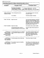
BMW334 Warming Cabinet
L --
I Symptom
---
Probable Cause
Co
erG1-
A
-
HEATING ELEMENT
Air Heater Resistance: 12 ohms
RESISTANCE CHECK Water Heater Resistance: 29 ohms (each)
ClRCULATlON FAN
DOES NOT WORK
Power not being delivered to fan
Check cabling between power switch and
fan; repair or replace
Fan is defective
Check fan and replace if necessary
Setpoint set too low
Check the Setpoint temperature: press PROG
and hold for 2 seconds: the &splay will show
alternately "SET" and "PNT" followed by the
Setpoint value. If value is incorrect, press UP
arrow button until value is correct (complete
programming details on pages 3 & 4)
Setpoint set too high
Check setpoint as above; adjust as needed
Thermocouple probe faulty, indicates to
controller that temperature lower than actual
Test probe; replace with known good one if
needed
CONTROLLER The thermocouple output is out of calibration
DISPLAY SHOWS with the controller's temperture conversion
TEMPERATURE circuit
LOWER OR HIGHER
THAN ACTUAL
The controller's temperature display can be
"offset" by up to plus/minus 20 degrees, to
better match the characteristics of the
thermocouple; (complete programming
details on pages 3 & 4)
FOOD TOO COOL
. . . FOOD TOO WARM
CONTROLLER
DISPLAY SHOWS
"Prob MESSAGE
CONTROLLER
DISPLAY SHOWS
"FAIL" MESSAGE
The thermocouple probe has failed open
Test probe and replace if needed
The controller's memory has failed the
test
Turn off power to the cabinet, pause, and
turn power back on;if message clears, let
unit run; if message rehlrns, controller is
faulty and must be replaced
powe,,p
Cleveland Range Inc.