1
2TWR2-1N-1B
18-BC51D2-3
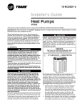
Pumps
2TWR1 & 2TWR2
ALL phases
of this installation
IMPORTANT
-- This Document
pack upon completion of work.
must
comply
is customer
with
NATIONAL,
property
STATE
and is to remain
These instructions
do not cover all variations
in
systems
nor provide
for every possible
contingency
to
be met in connection
with installation.
All phases
of
this installation
must comply with NATIONAL,
STATE
AND LOCAL CODES. Should further information
be
desired or should particular
problems arise which are not
covered sufficiently for the purchaser's
purposes, the matter
should be referred to your installing dealer or local distributor.
©
AND LOCAL
with this unit.
CODES
Please
return
to service
information
5 FT. ABOVE UNIT-UNRESTRICTED
A. GENERAL
The following instructions
Pump Units.
cover 2TWR1 and 2TWR2 Heat
NOTE:
These outdoor units may be used with indoor units
equipped with Thermostatic Expansion Valve or Accutron rM
Flow Control Check Valve (F.C.C.V.) assembly for refrigerant
flow control only.
Check for transportation
damage after unit is uncrated.
Report promptly, to the carrier, any damage found to the unit.
To determine
the electrical power requirements
of the unit,
refer to the nameplate
of the unit. The electrical power
available must agree with that listed on the nameplate.
The Weathertron
®Heat Pump has been designed and
manufactured
to withstand
and operate in severe winter
conditions. However, there are precautionary
steps which
should be taken at the time of installation
which -will help
assure the efficient operation of the unit. It is recommended
that these precautions
be taken for units
being installed
in areas where snow accumulation
and
prolonged
below freezing
temperatures
occur.
1,
Units should be elevated 3 to 12 inches above the pad or
rooftop, depending on local weather. This additional
height will allow better drainage of snow and ice (melted
during defrost cycle) prior to its refreezing. This should
prevent a build-up of ice around the unit which occurs
when unit is not elevated. Insure
that drain holes in
unit base pan are not obstructed
preventing
draining
of defrost
water.
2. If possible, avoid locations that are likely to accumulate
snow drifts. If not possible, a snow drift barrier should be
installed around the unit to prevent a build-up of snow
on the sides of the unit and should be of sufficient
distance from the unit to prevent restriction
of airflow to
and from the unit. Also allow for proper maintenance
space. The barrier should be constructed
of materials
which will blend in with the building design.
3,
Avoid locating the unit where condensation
and freezing
of defrost vapor may annoy the customer. For instance,
installing the unit under a bedroom, ldtchen, or picture
window may be annoying to the customer since condensate and fog will occur during the defrost cycle.
4,
Avoid locating the unit under the eaves or other overhead structures
as sizeable icicles may form and the unit
may be damaged by these falling icicles.
B. LOCATION AND PREPARATION
OFTHE UNIT
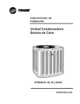
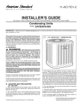
1. When removing unit from the pallet, notice the tabs on
the basepan. Remove tabs by cutting with a sharp tool as
shown on page 2, Figure 2, and slide unit off of pallet.
2,
The unit should be set on a level support pad at least as
large as the unit base pan, such as a concrete slab. If this
is not the application used please refer to application
bulletin "Trane APB2001-02".
3,
The support pad must NOT be in direct contact with any
structure.
Unit must be positioned a minimum of 12"
from any wall or surrounding
shrubbery
to insure
adequate airflow. Clearance
must be provided in front of
control box (access panels) and any other side requiring
service access to meet National Electrical Code. Also, the
unit location must be far enough away from any struc-
|nsta||er's
@
Guide
BASEPAN
D. INSTALLING
TAB REMOVAL
REFRIGERANT
If using existing refrigerant
are brazed, not soldered.
Condensing
LINES
lines make certain that all joints
units have provisions
for braze connections.
Pressure taps are provided on the service valves of outdoor
unit for compressor
suction and liquid pressures.
ture to prevent excess roof run-off water from pouring
directly on the unit. Do not locate unit(s) close to
bedroom(s).
4. The top discharge area must be unrestricted
five (5) feet above the unit.
6. The maximum length of refrigerant
lines from outdoor
to indoor unit should NOT exceed sixty (60) feet.
7. If outdoor unit is mounted above the air handler, maximum lift should not exceed sixty (60) feet (suction line). If
air handler is mounted above condensing unit, maximum lift should not exceed sixty (60) feet (liquid line).
8. Locate and install indoor coil or air handler in accordance with instruction
included with that unit.
TM
FLOW CONTROL
VALVE
If the indoor unit System Refrigerant
Flow control is an
Accutron TM orifice and check valve assembly, an orifice size
change may be necessary.
The outdoor model determines
the required orifice size.
Check the listed orifice size on nameplate
of the selected
outdoor model. If the indoor unit is factory shipped with a
diffhrent orifice size, the orifice must be changed to obtain
system rated performance.
IMPORTANT'.
The outdoor unit is shipped with the proper size orifice and a
stick-on orifice size label in an envelope attached to the
outdoor unit. Outdoor unit nameplate will have correct orifice
size specified as BAYFCCV --- A for rated performance.
BRAZE TYPE
iNDOOR
The gas line must
always be insulated.
for at least
5. When the outdoor unit is mounted on a roof, be sure the
roof will support the unit's weight. Properly selected
isolation is recommended
to prevent transmission
to the
building structure.
C. ACCUTRON
The indoor end of the recommended
refrigerant
line sets may
be straight or with a 90 degree bend, depending upon
situation requirements.
This should be thoroughly checked
out before ordering refrigerant
line sets.
In scroll compressor applications, dome temperatures may
be hot. Do not touch top of compressor, may cause minor to
severe burning.
The units are factory charged with the system charge required -when using fifteen (15) f_et of connecting line. Unit
nameplate
charge is the same.
Final refrigerant
charge adjustment
is necessary.
the Charging Charts in the outdoor unit Service Facts.
1. Determine
2. Consider
the most practical
Use
way to run the lines.
types of bends to be made and space limitations.
NOTE:
Large diameter tubing will be very difficult to rebend once it
has been shaped.
3,
Determine
ant tubing
the best starting point for routing the refriger- -INSIDE OR OUTSIDE THE STRUCTURE.
4. Provide a pull-thru
hole of sufficient
liquid and gas lines.
5. Be sure the tubing is of sufficient
6. Uncoil the tubing
size to allow both
length.
--- do not kink or dent.
7. Route the tubing making all required bends and properly
secure the tubing before making connections.
8. To prevent a noise within the building structure
due to
vibration transmission
from the refrigerant
lines, the
following precautions
should be taken:
a. When the refrigerant
lines have to be fastened to floor
joists or other framing in a structure,
use isolation
type hangers.
END
SEALING
CAP
LiQUiD
LiNE SERVICE
VALVE
ROLLED
CAP_
@
EDGE TO
CAPTIVATE
/
STEM
sEO.ffS ,S'DEOF
---- .EX.EADgEM
SERVICE
PORT
_
_
/
--
/
LIQUID LINE
CONNECTION
© 2002 American Standard Inc. All Rights Reserved
18-BC51 D2-3
|nsta||er's
@
®
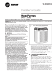
GAS LiNE BALL SERVICE VALVE
Guide
GAS LiNE SERVICE VALVE
ROLLED
CAP
---__
,I-J,
1/4 TURN ONLY
COUNTERCLOCKWISE
FOR FULL OPEN
I
_
CAP_
@
/
EDGE TO
CAPTIVATE
STEM
POSITION
VALVEBTEM
HEXHEADED
VALVE SYSTEM
UNIT SIDE OF
UNITSIDE
OFVALVE
SERVICE
VALVE
SERVICE-_q
PRESSURETAPPORT
/
GAS
LINE CONNECTION
PORT
/
GASLINE
CONNECTION
o,.
CAP
_
6. Precautions
should be taken to avoid heat damage
to the pressure
tap valve core during
brazing.
It is
recommended
that the pressure
tap port valve
core be removed
and a wet rag wrapped
around
the valve body.
(_
COOL
L_ZI
i
BODY
_
NOTE:
Use care to make sure that no moisture
port, while wet rag is being used.
17_ q
CORE
b. Isolation hangers should also be used -when refrigerant lines are run in stud spaces or enclosed ceilings.
c. Where the refrigerant
lines run through
they should be insulated and isolated.
d. Isolate
a wall or sill,
the lines from all ductwork.
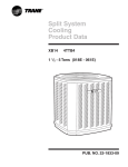
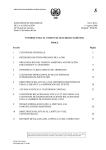
E. SERVICE VALVE OPERATION
enters pressure
NOTE:
Precautions should be taken to avoid heat damage to
basepan during brazing. It is recommended to keep the
flame directly off of the basepan.
7. Use a Dry Nitrogen Purge and Brazing Alloy without
flux when brazing the field line to the copper thctory
connection. Flow dry nitrogen into either valve pressure
tap port, thru the tubing and out the other port while
brazing.
BRASS LIQUID AND GAS LINE SERVICE VALVES
The Brass Liquid and Gas Line Service Valves are factory
shipped in the seated position to hold factory charge. The
pressure tap service port (when depressed) opens only to the
field brazing side of the valve when the valve is in the seated
position. The liquid line valve is not a back seating valve (see
WARNING below).
LEAK CHECK
Extreme caution should be exercised when opening the
Liquid and Gas Line Service Valves. Turn valve stem
counterclockwise only until the stem contacts the roiled
edge. (See Figures 4 and 6) No torque is required.
After the brazing operation of refrigerant
lines to both the
outdoor and indoor unit is completed, the field brazed
connections must be checked for leaks. Pressurize
through
the service valve ports, the indoor unit and field refrigerant
lines with dry nitrogen to 350-400 psi. Use soap bubbles or
other leak-checking
methods to see that all field joints are
leak-free! If not, release
pressure;
then repair!
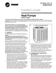
BRASS GAS LINE BALL SERVICE VALVE
The Brass Gas Line Service Valve is shipped in the closed
position to hold the factory refrigerant
charge. The pressure
tap service port (when depressed) opens only to the field
brazing side when the valve is in the closed position.
The Gas Line Service Valve is full open with a 1/4 turn.
Figure 5.
3. Cut and fit tubing, minimizing
4. Insulate
18-BC51 D2-3
copper stub
of stub tubes
the use of sharp 90 ° bends.
the entire gas line and its fittings.
5. Do NOT allow uninsulated
contact with bare gas line.
8. Braze using accepted
good brazing
techniques.
IMPORTANT:
Replace pressure tap port valve core before attaching hoses for
evacuation.
SYSTEM EVACUATION
NOTE:
Since the outdoor unit has a refrigerant
liquid line valves must remain closed.
charge, the gas and
See
BRAZING REFRIGERANT LINES
1. Remove lower access cover to access service valves.
2. Before brazing, remove plugs from external
tubes. Clean internal and external surfaces
prior to brazing.
tap
liquid line to come in direct
1. Upon completion
lines and indoor
line valves.
of leak check, evacuate the refrigerant
coil before opening the gas and liquid
2. Attach appropriate
hoses from manifold
and liquid line pressure taps.
gauge to gas
NOTE:
Unnecessary switching of hoses can be avoided and corn=
plete evacuation of all lines leading to sealed system can be
accomplished with manifold center hose and connecting
branch hose to a cylinder of HCFC-22 and vacuum pump.
3
|nstaI|er's
3. Attach
center
4. Evacuate
until
350 microns.
Guide
hose
the
of manifold
micron
gauges
gauge
to vacuum
reads
no higher
pump.
than
5. Close offvalve to vacuum pump and observe the micron
gauge. If gauge pressure rises above 500 microns in one
(1) minute, then evacuation is incomplete or system has
a leak.
6. If vacuum gauge does not rise above 500 microns
(1) minute, the evacuation
should be complete.
5. Provide flexible electrical conduit whenever vibration
transmission
may create a noise problem within the
structure.
6. The use of color coded low voltage wire is recommended
to simplify connections between the outdoor unit, the
thermostat
and the indoor unit.
Table 1 --- NEC Class II Control Wiring
in one
24 VOLTS
7. With vacuum pump and micron gauge blanked off; open
valve on HCFC-22 cylinder and charge refrigerant
lines
and indoor coil with vapor to tank pressure of HCFC-22
supply.
NOTE:
DO NOT VENT REFRIGERANT
INTO THE ATMOSPHERE.
8. Close valve on HCFC-22 supply cylinder. Close valves on
manifold gauge set and remove refrigerant
charging
hoses from liquid and gas pressure tap ports.
NOTE:
A 3/16" Allen wrench is required to open liquid line service
valve. A 1/4" Open End or Adjustable wrench is required to
open gas line valve. A 3/4" Open End wrench is required to
take off the valve stem cap.
9. The liquid line shut-offvalve
ean now be opened.
Remove shut-offvalve
cap. Fully insert hex wrench into
the stem and backout counterclockwise
until valve stem
just touches rolled edge (approximately
five [5] turns)
observing WARNING
statement
on page 3. See Figure 4.
10. Replace liquid service pressure tap port cap and valve
stem eap. These caps MUST BE REPLACED
to
prevent leaks. Replace valve stem and pressure tap cap
finger tight, then tighten an additional
1/6 turn.
11. The gas valve can now be opened. For a ball type gas
valve, open the gas valve by removing the shut-offvalve
cap and turning the valve stem 1/4 turn counterclockwise, using 1/4" Open End or Adjustable wrench. See
Figure 5. For brass gas line service valve opening, follow
9 and 10 above. See Figure 6.
12. The gas valve is now open for refrigerant
flow. Replace
valve stein cap to prevent leaks. Again, these eaps
MUST BE REPLACED
to prevent leaks. Replace valve
stem and pressure tap cap finger tight, then tighten an
additional 1/6 turn. See Figure 4.
If refrigerant
lines are longer than 15 feet and/or a difi_rent
size than recommended,
it will be necessary to adjust system
refrigerant
charge upon completion of installation.
See unit
Service Facts.
F. ELECTRICAL
WIRE SIZE
7.
8.
LENGTH
18 AWG
150 FT
16 AWG
225 FT.
14 AWG
300 FT.
Table 1 defines maximum total length of low voltage
wiring from outdoor unit, to indoor unit, and to
thermostat.
Mount the indoor thermostat
in accordance with instruction included -with the thermostat.
Wire per appropriate
hook-up diagram (included in these instructions).
G. DEFROST
CONTROL
The demand defrost control measures
heat pump outdoor
ambient temperature
with a sensor located outside the
outdoor coil. A second sensor located on the outdoor coil is
used to measure the coil temperature.
The diffhrence between the ambient and the colder coil temperature
is the
diffhrence or delta-T measurement.
This delta-T measurement is representative
of the operating state and relative
capacity of the heat pump system. By measuring
the change
in delta-T, we can determine
the need for defrost. The coil
sensor also serves to sense outdoor coil temperature
for
termination
of the defrost cycle.
FAULT iDENTiFICATiON
A fault condition is indicated by the flashing light on the
defrost control inside the heat pump control box.
In normal operation, the defrost control light will flash once
each second. If the light is flashing more than once per
second or not at all, refer to the service manual for that unit.
PiN iDENTiFiCATiON (See Figure 7.)
1. TEST_COMMON
(Shorting any of the other pins to this
pin causes the function of the other pin to be executed.
Leaving this pin open results in the normal mode of
operation.)
2. TST = Test (Shorting TEST_COMMON
speeds up all defrost board timings.)
©
CONNECTIONS
MAX. WIRE
to this pin
PiN iDENTiFiCATiON
Z
0
When installing or servicing this equipment, ALWAYS
exercise basic safety precautions to avoid the possibility
of electric shock.
1. Power -wiring and grounding
with local codes.
of equipment
2. Power supply must agree with equipment
o
o
must comply
nameplate.
LL
3. Install
4. Ground
4
a separate
the outdoor
disconnect
switch
at the outdoor
unit per local code requirements.
unit.
° m
LL
I
\
p-
18-BC51 D2-3
|nsta||er's
3. FRC_DFT = Forced Defrost (Short TEST_COMMON
this pin for two (2) seconds to initiate a forced defrost.
Remove the short after defrost initiates.)
to
DEFROST CONTROL CHECKOUT
Normal operation requires:
a. LED on board flashing
1 time/second.
b. 24V AC between
R & B
c. 24V AC between
Y & B with unit operating
d. Defrost initiation
TEST_COMMON
when FRC_DFT
pin.
If a defrost control problem is suspected,
information
in control box.
pin is shorted
to
refer to the service
ODS=A
AND CHECKOUT
Final phases of this installation
are the unit Operational
and
Checkout Procedures which are found in this instruction
on
page 8. To obtain proper performance,
all units must be
operated and charge adjustments
made in accordance with
procedures found in the Service Facts.
J. ELECTRIC
Do NOT connect 24 VAC to T1 (ODS=A) terminal.
thermistor WILL BE BLOWN.
H. COMPRESSOR
I. OPERATIONAL
PROCEDURES
Guide
HEATERS
Electric heaters, if used, are to be installed in the air handling device according to the instructions
accompanying
the
air handler and the heaters.
K. START CONTROL
Some models have quick start components which are fhctory
installed. For models that do not have factory installed start
components, provisions are made for a field installed start kit
accessory. When adding an accessory, follow the instructions
provided with the kit.
L. OUTDOOR THERMOSTAT
START UP
After all electrical wiring is complete, SET THE THERMOSTAT SYSTEM SWITCH IN THE OFF POSITION SO
COMPRESSOR
WILL NOT RUN, and apply power by closing
the system main disconnect switch. This will activate the
compressor sump heat (where used). Do not change the
Thermostat
System Switch until power has been applied for
one (1) hour. Following this procedure will prevent potential
compressor overload trip at the initial start-up.
An outdoor thermostat
TAYSTAT250B may be field installed.
For data, see wiring diagram attached to unit and instruction
sheet packaged with outdoor thermostat.
M. SEACOAST
SALT SHIELD
Units installed -within one mile of salt water including
seacoasts and inland waterways,
require the addition of
BAYSEAC001 (Seacoast Kit) at the time of installation.
IMPORTANT:
See Limited Warranty information in Use and Care Manual.
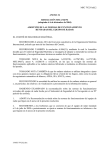
TYPICAL
)iR H,',,I,,D
ER
T '3T/_T
FIELD HOOK=UP DIAGRAMS
HF,',,T PU:_4P
@
_---'i_
L ...
'S
iAR A,i;
SP II)
,::, R HA!',[) ER
;,
II [/; i
,.
i
._,."...
0 i_
R-n
,
P U_,'I
y
0
:iK( X1_)
G;
(
F!K X2 )
:ii \
I[...,:_
--
_-
--
....
.__c.P._9.'
_i ._u4o{_.
-_
i
i
i
iB;
i
B
}
;
i
_----_,;
ii'
,,
L....[_
:
[
> l i, r riD ::<W
_"--'_!R ( T )
D-
[/01{ 6
D
i
B 5290,>03
PR i,i
F;;' FROM , i :1;'9 )4PO{Z
Notes:
LEGEND
1. Be sure power supply agrees with equipment nameplate.
2. Power wiring and grounding of equipment must comply with local codes.
3. Low voltage wiring to be No. 18 AWG minimum conductor.
4. ODT-B must be set lower than ODT-A.
,5. If outdoor thermostats (ODT) are not used, connect W1 to W2 and W3.
6. N/A to programmable thermostat.
18-BC51 D2-3
.....
FACTORY WIRING
FIELD WIRING
5
Installer's
Guide
SERViCr
PANE[
.......... _
IIICIRiCAI
ANI) iRIFIRiG_RA_i
COMPONENT C[LARA_C_S
PER PREVAilinG
CO_LS
iOP DiSCiiARGE AREA SiiOULD BE
UNRESTRICTED FOR AT LEAST 1524 (5 FEET}
A_OVE UN[_
d_lJ ¸ S_IOU[b BE PEACED SO ROOi
i!_O[[
¸ WATE[i _O[S NO] _O_R _I_E¢iL¥
ON UNi]
£_i) SHOWi) _i_ A/ JI_ASI¸ 30_ (i_ ¸¸} EROM WA[i ANJ)
ALL SORROUNDiNG SHRUBBERY O_ IWO SinES¸
OTFIER TWO Si_[S
U_R_STRiCT[_
F A_EL
_
L
25
2_
2 (bS)
7
i_
i011£ ..............
I O_i ?9 I &( (
A
:J
I I(/;I)
t [!
S _,,' '3
V ,
'
I t4A
BRAZED CO,i!'E,30l
WI I _,1
SAE FLARE
PRESSUR Ts, P f TT_G
j;,
.
. ---
28 f, ',
1_8} DIA
K 0
_l H........
22 2 7/8}
DIA
OlE
i_ C,91TR,PL
BOX tX) I 'C4 [:OH EL E( R ( AL
/()W_ i SIJP[ ' _ .....
j
j
i
(;'U [J _[
S R_iC[
?/_,'E,
-''1''_=
@ [: HA [ BE{;}
H T
COr_/ECl }01i /i I
/,I
SA[
F
LARE PRESSURE I_P
il IGS
j
,
,
I
I_
_
i
L
il
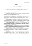
FIG. 1
\
KO
,,
[OH AiTER_A[E
C i IleAl
OJ Iq',,
G_
\ GAS i iNE I/4 iWiN SAil
SIRVICI
ID
FE_£LE BRAZED CO_N[CTiO_
FiARE PR[SSbR_ TAP FiTTi_6
VAJVL
'l)'
_IT_ [/4 ¸¸ SA[
GAS Li:/
¢ON_[¢[I()_
SIVCE
VALVE,
x
I D FEI_'ALF BRAZED
WlTli
i/4 '¸ SA[ FLARE
i_R[S$[iR_ lAP i¸ il_ iN6
MODELS
BASE
FIG.
A
B
D
E
F
G
H
J
K
2TWR1018A
2
2
651 (25-5/8)
724 (28-1/2)
651
(25-5/8)
5/8
1/4
127 (5)
57 (2-1/4)
180 (7-1/8)
44 (1-3/4)
457 (18)
2TWR1024A
2
2
651 (25-5/8)
724 (28-1/2)
651
(25-5/8)
3/4
5/16
127 (5)
57 (2-1/4)
180 (7-1/8)
44 (1-3/4)
457 (18)
2TWR1030A
2
2
730 (28-3/4)
724 (28-1/2)
651
(25-5/8)
3/4
5/16
137
(5-3/8)
65
210
57
457
2TWR1036A
2
2
730 (28-3/4)
724 (28-1/2)
651
(25-5/8)
7/8
3/8
137
(5-3/8)
65 (2-5/8)
210 (8-1/4)
57 (2-1/4)
457 (18)
2TWR1042A
3
2
832 (32-3/4)
829 (32-5/8)
756
(29-3/4)
7/8
3/8
137
(5-3/8)
86
(3-3/8)
210
(8-1/4)
79
(3-1/8)
508
(20)
2TWR1048A
3
2
832 (32-3/4
829 (32-5/8)
756
(29-3/4)
1-1/8
3/8
137
(5-3/8)
86
(3-3/8)
210
(8-1/4)
79
(3-1/8)
508
(20)
2TWR1060A
4
1
841 (33-1/8)
946 (37-1/4)
870
(34-1/4)
1-1/8
3/8
152
(6)
98
(3-7/8)
219
(8-5/8)
86
(3-3/8)
508
(20)
2TWR2018A
2
2
651 (25-5/8)
724 (28-1/2)
651
(25-5/8)
5/8
1/4
127
(5)
57 (2-1/4)
180 (7-1/8)
44 (1-3/4)
457 (18)
2TWR2024A
2
2
730 (28-3/4)
724 (28-1/2)
651
(25-5/8)
3/4
5/16
137
(5-3/8)
65
(2-5/8)
210
(8-1/4)
57
(2-1/4)
457
(18)
2TWR2030B
2
2
832 (32-3/4)
724 (28-1/2)
651
(25-5/8)
3/4
5/16
137
(5-3/8)
65
(2-5/8)
210
(8-1/4)
57
(2-1/4)
457
(18)
2TWR2036A
3
1
832 (32-3/4)
829 (32-5/8)
756
(29-3/4)
7/8
3/8
143
(5-5/8)
92
(3-5/8)
210
(8-1/4)
79
(3-1/8)
508
(20)
2TWR2042A
3
1
832 (32-3/4)
829 (32-5/8)
756
(29-3/4)
7/8
3/8
143
(5-5/8)
92
(3-5/8)
210
(8-1/4)
79
(3-1/8)
508
(20)
2TWR2048A
3
1
933 (36-3/4)
829 (32-5/8)
756
(29-3/4)
1-1/8
3/8
143
(5-5/8)
92
(3-5/8)
210
(8-1/4)
79
(3-1/8)
508
(20)
2TWR2060A
4
1
1045 (41-1/8)
946 (37-1/4)
870
(34-1/4)
1-1/8
3/8
98
(3-7/8)
219
(8-5/8)
86
(3-3/8)
508
C
152
(6)
(2-5/8)
(8-1/4)
From
6
Dwg.
(2-1/4)
21D152898
(18)
(20)
Rev.
9
18-BC51 D2-3
|nstal|er's
MOUNTING
Guide
HOLE LOCATION
Note: All dimensions are in IVllVl(Inches).
BASE 2
BASE 3
NOTE: For model base size,
see table on page 6.
........................................................
$99
(255
_?f
BASE 4
18-BC51 D2-3
(2864)
n_
......................................................
4
From Dwg. 21 D152637 Rev. 1
7
|nsta||er's
Guide
CHECKOUT
After installation
1. Refrigerant
2. Suction
has been completed,
Line, Leak checked
Lines and Fittings
it is recommended
that
..................................
properly
insulated
...........
3. Have all Refrigerant
Lines been secured and
isolated properly? ........................................................
]
[
]
[
[
5. Verify tightness
[
connects
the entire
[
4. Have passages through masonry been sealed?
If mortar is used, prevent mortar from coining
into direct contact with copper tubing ........................
of all electrical
PROCEDURE
...................
6. Observe outdoor fan during on cycle for clearance
and smooth operation
.................................................
[
7. Indoor coil drain line drains freely. Pour water
into drain pan ..............................................................
[
TROUBLESHOOTING
]
]
system be checked
against
the following list:
8. Supply registers and return grilles open and
unobstructed
...............................................................
[
]
9. Return
[
]
10. Thermostat
thermometer
is accurate. Check
against a reliable thermometer.
Adjust per
instructions
with thermostat
......................................
[
]
11. Is correct speed tap being used?
(Indoor blower motor) .................................................
[
]
12. Operate complete system in each mode to
insure safe operation ...................................................
[
]
CHART
air filter installed
............................................
m WHAT TO CHECK
SYSTEM
FAULTS
REFRIGERANTCIRCUIT
Head Pressure Too High
Head Pressure Too Low
s
s
P
P
s
s
p
p
SuctionPressureTooHigh
SuctionPressureTooLow
LiquidBefrig Eloodback(TXV)
IELCoil Frostiag
ELECTRICAL
Compressor& OB Fan
Won't Start
s s
s s
CompressorWill Not Start
But OD EalqRuns
OD FanWon't Start
s
s
ss
CompressorHums ButWon't Start
ii
$
p
$
p
P
P
CompressorCycleson I01.
IELBlower Won't Start
P
Ss PP P
P
DEFROST
UnitWon't Initiate Defrost
DefrostTerminateson Time
Unit Icing Up
C - Cooling
H - Heating
P - PrimaryCauses
S - SecondaryCauses
"k - 3 PhaseOnly
C
T J.N£
Trane
A business of
American Standard Companies
www.trane.com
Literature Order Number
2TWR2-iN-1B
File Number
SV-UN-S/SP-2TWR2-1N-1B
Supersedes
2TWR2-1N-1A
Stocking Location
PI Louisville & Webb/Mason-Houston
Trane has a policy of continuous product and product data improvement
design and specifications without notice.
RI.
and it reserves the right to change
2/03