Download MODEL G8712/G8713 ENGINE CRANE
Transcript
MODEL G8712/G8713 ENGINE CRANE INSTRUCTION SHEET G8712 Shown Copyright © september, 2008 By Grizzly Industrial, Inc. UPDATED FEBRUARY 2009. Warning: No portion of this Instruction sheet may be reproduced in any shape Or form without the written approval of Grizzly Industrial, inc. #cr11160 printed IN CHINA This manual provides critical safety instructions on the proper setup, operation, maintenance and service of this machine/equipment. Failure to read, understand and follow the instructions given in this manual may result in serious personal injury, including amputation, electrocution or death. The owner of this machine/equipment is solely responsible for its safe use. This responsibility includes but is not limited to proper installation in a safe environment, personnel training and usage authorization, proper inspection and maintenance, manual availability and comprehension, application of safety devices, blade/cutter integrity, and the usage of personal protective equipment. The manufacturer will not be held liable for injury or property damage from negligence, improper training, machine modifications or misuse. Some dust created by power sanding, sawing, grinding, drilling, and other construction activities contains chemicals known to the State of California to cause cancer, birth defects or other reproductive harm. Some examples of these chemicals are: • • • Lead from lead-based paints. Crystalline silica from bricks, cement and other masonry products. Arsenic and chromium from chemically-treated lumber. Your risk from these exposures varies, depending on how often you do this type of work. To reduce your exposure to these chemicals: Work in a well ventilated area, and work with approved safety equipment, such as those dust masks that are specially designed to filter out microscopic particles. Safety Instructions for Engine Cranes 1.PREVENTING CRANE DAMAGE. Do not overload this engine crane beyond its load rating. 2. SUPPORTING LOAD SAFELY. Never allow anyone to work under a load supported by an engine crane. NEVER allow the engine crane to be the sole support for the load. Use jack stands to support the load. 7. INSTALLING ENGINE SAFELY. Keep as much of your body as possible out from underneath the vehicle when reinstalling the engine. 8. USING THE CORRECT MACHINERY. Never modify this engine crane or use boom extensions. Use the correct machinery for the task at hand. 3. CORRECT WORK AREA. ONLY use this engine crane on a hard level surface capable of sustaining the load being lifted. 9. SERVICE SAFETY. Any engine crane cylinder repair must only be performed by a qualified hydraulic specialist. 4. USING ACCESSORIES. Only connect lifting hooks, fasteners, chains, or straps at points that can safely support the load and prevent unpredictable load swing or shift. 10. LOWERING LOAD SAFELY. Never lower the boom quickly so the load drops and slams onto a pallet or the floor. 5. SAFE WORK AREA. Always make sure that when the engine or load is about to be hoisted that the floor is clean and all tripping hazards are removed. 6. REMOVING ENGINE SAFELY. Apply the parking brake, and use wheel chocks against the tires to prevent accidental rolling when engines are being removed or installed. Like all machinery there is potential danger when operating this machine. Accidents are frequently caused by lack of familiarity or failure to pay attention. Use this machine with respect and caution to decrease the risk of operator injury. If normal safety precautions are overlooked or ignored, serious personal injury may occur. G7812/G7813 Engine Crane 11. KEEPING CHILDREN SAFE. Never allow children to play with or near the engine crane while in use or in storage. 12.PREVENTING CRANE TIPPAGE. Never attempt to roll the engine crane with the boom in the raised position, or the load and crane may tip due to a high center of gravity. Only move with the load as low as possible. No list of safety guidelines can be complete. Every shop environment is different. Always consider safety first, as it applies to your individual working conditions. Use this and other machinery with caution and respect. Failure to do so could result in serious personal injury, damage to equipment, or poor work results. -1- Specifications Items Needed for Setup Model: G8712 FOLDING ENGINE CRANE • Maximum Load (Boom Retracted): 2-Tons. • Maximum Load (Boom Extended): 1⁄ 2-Ton. • Base Length: 723/8". • Base Width: 401/4". • Maximum Height: 951/4" (at 1/2 Ton). • Maximum Height: 821/2" (at 2 Tons). The following items are needed to complete the setup process, but are not included with your machine: Model: G8713 ENGINE CRANE • Maximum Load (Boom Retracted): 2-Tons. • Maximum Load (Boom Extended): 1⁄ 2-Ton. • Base Length: 92". • Base Width: 51". • Maximum Height: 98" (at 1/2 Ton). • Maximum Height: 98" (at 2 Tons). Setup Safety This machine presents serious injury hazards to untrained users. Read through this entire manual to become familiar with the controls and operations before starting the machine! Wear safety glasses during the entire setup process! This machine and its components are very heavy. Get lifting help or use power lifting equipment such as a forklift to move heavy items. -2- Description Qty •Assistant...................................................... 1 •Safety Glasses............................................ 1 • Wrench 22mm............................................. 1 • Wrench 25mm............................................. 1 • Wrench 27mm............................................. 1 • Crescent Wrench......................................... 1 Unpacking Your machine was carefully packaged for safe transportation. Remove the packaging materials from around your machine and inspect it. If you discover the machine is damaged, please immediately call Customer Service at (570) 546-9663 for advice. Save the containers and all packing materials for possible inspection by the carrier or its agent. Otherwise, filing a freight claim can be difficult. When you are completely satisfied with the condition of your shipment, inventory the contents. SUFFOCATION HAZARD! Immediately discard all plastic bags and packing materials to eliminate choking/suffocation hazards for children and animals. If any nonproprietary parts are missing (e.g. a nut or a washer), we will gladly replace them; or for the sake of expediency, replacements can be obtained at your local hardware store. G7812/G7813 Engine Crane Model G8712 Inventory Model G8713 Inventory Box 1: (Figure 1) Qty A. Frame Base................................................. 1 B. Hydraulic Ram............................................. 1 C. Pump Handle............................................... 1 Box 1: (Figure 2) Qty A. Rear Support............................................... 1 B. Rear Legs w/Casters................................... 1 C. Intermediate Legs........................................ 1 Box 2: (Figure 1) Qty D. Front Leg..................................................... 2 E. Boom........................................................... 1 F. Boom Extension.......................................... 1 G. Chain w/Hook.............................................. 1 H. Main Support Post....................................... 1 I. Support Straps............................................ 2 J. Hardware Box.............................................. 1 —Hex Bolt M14-2 x 110 (Support Straps)... 2 —Hex Bolt M16-2 x 120 (Support Straps)... 2 —Hex Bolt M14-2 x 100 (Support Post)...... 2 —Hex Bolt M16-2 x 85 (Ram)..................... 1 —Hex Bolt M14-2 x 80 (Chain w/Hook)...... 1 —Hex Bolt M16-2 x 70 (Boom)................... 1 —Hex Bolt M18-2.5 x 110 (Boom)............... 1 —Hex Bolt M16-2 x 90 (Boom Extension).. 1 —Frame Pin W/Cotter Pin (Front Legs)...... 4 —Hex Nut M14-2 (Hardware)...................... 5 —Hex Nut M16-1.5 (Hardware)................... 5 —Hex Nut M18-2.5 (Hardware)................... 1 —Flat Washer 14mm (Hardware)................ 5 —Flat Washer 16mm (Hardware)................ 5 —Flat Washer 18mm (Hardware)................ 1 Box 2: (Figure 2) Qty D. Front Legs w/Casters.................................. 2 E. Support Straps............................................ 1 F. Hydraulic Ram............................................. 1 G. Pump Handle............................................... 1 A J F C D Box 3: (Figure 2) Qty H. Chain w/Hook.............................................. 1 I. Main Support Post....................................... 1 J. Boom........................................................... 1 K. Boom Extension.......................................... 1 L. Cross Tube.................................................. 1 M. Hardware Box.............................................. 1 —Hex Bolt M14-2 x 120 (Cross Tube)......... 2 —Hex Bolt M16-2 x 90 (Boom Extension).. 1 —Hex Bolt M14-2 x 80 (Legs Front/Rear)... 5 —Hex Bolt M16-2 x 70 (Boom)................... 1 —Hex Bolt M14-2 x 100 (Straps/Post)........ 4 —Hex Bolt M16-2 x 110 (Straps)................. 2 —Hex Bolt M16-2.5 x 100 (Rear Support).. 2 —Hex Bolt M16-2 x 90 (Ram)..................... 1 —Hex Bolt M20-2.5 x 120 (Boom).............. 1 —Hex Nut M14-2 (Hardware).....................11 —Hex Nut M16-1.5 (Hardware)................... 7 —Flat Washer 14mm (Hardware)...............11 —Flat Washer 16mm (Hardware)................ 7 —Flat Washer 20mm (Hardware)............... 1 —Flat Washer 20mm (Hardware)............... 1 I B G L E M C H A Figure 1. G8712 Inventory. E NOTICE If you can't find an item on this list, check the mounting location on the machine or examine the packaging materials carefully. Occasionally we pre-install certain components for shipping purposes. G7812/G7813 Engine Crane J I B F H D K G Figure 2. G8713 Inventory. -3- Hardware Recognition Chart -4- G7812/G7813 Engine Crane Assembly (G8712) To avoid injury when completing these steps, please get the help of an assistant. When completed, your new engine crane will look like the one shown in (Figure 3). 2. Position the main support post onto the base (Figure 5), and secure it in place with two M14-2 x 100 hex bolts, washers, and nuts. Support Strap Main Support Post Frame Base Figure 3. Model G8712 ready for use. To assemble your crane: Note: All fasteners must be kept finger tight until final assembly. 1. Insert the two legs into the frame base (Figure 4), and secure them in place with the four eye pins and cotter pins. Note: Each leg has two pins and three pin holes in the frame base (Figure 4). Pin 1 is the pivot pin and remains in hole A. Pin 2 is the removable lock pin—when inserted in hole B, the leg is locked in the down position. When the Pin 2 is inserted in hole C, the leg is locked in the raised position. Frame Base Pin 1 Figure 5. Main support assembly. 3. Install both support straps on the main support post (Figure 5) with two M16-2 x 120 hex bolts, washers, and nuts. 4. Connect both support straps to the frame base (Figure 5) with two M14-2 x 110 hex bolts, washers, and nuts. C Pin 2 A B Figure 4. Base assembly. G7812/G7813 Engine Crane -5- 5. Attach the bottom of the hydraulic cylinder to the pad on the main support post (Figure 6) with one M16-2 x 85 hex bolt, washer, and nut. Assembly (G8713) To avoid injury when completing these steps, please get the help of an assistant. When completed, your new engine crane will look like the one shown in (Figure 7). Boom Boom Extension Main Support Post Ram Hydraulic Cylinder Chain Figure 7. Model G8713 ready for use. To assemble your crane: Note: All fasteners must be kept finger tight until final assembly. Figure 6. Boom assembly. 6. Install the boom on the top of the main support post (Figure 6) with one M18-2 x 110 hex bolt, washer, and nut. 7. While your assistant holds the boom up, connect the ram to the boom (Figure 6) with one M16-2 x 70 hex bolt. 8. Insert the boom extension into the boom, making sure that the slot for chain is facing down (Figure 6). 1. Using two M14-2 x 120 hex bolts, washers, and nuts, connect the two intermediate legs together with the cross tube (Figure 8). Rear Support Cross Tube Intermediate Leg Rear Support Leg Front Leg 9. Select one of the four load rating holes in the boom (Figure 6), and secure the boom extension in that rated load position with one M16-2 x 90 hex bolt, washer, and nut. Figure 8. Base assembly. 10. Attach the chain to the end of the boom assembly (Figure 6) and secure it in place with one M14-2 x 80 hex bolt, washer, and nut. 2. Insert the two intermediate legs into the rear support (Figure 8), and secure in place with two M16-2 x 100 hex bolts, washers, and nuts. 11. Tighten all fasteners. 12. Make sure hydraulic reservoir is full and bled. Refer to Maintenance on Page 15 for procedures. -6- G7812/G7813 Engine Crane 3. Insert the rear support legs equipped with casters into each side of the rear support (Figure 8), and secure the legs in place with two M14-2 x 80 hex bolts, washers, and nuts. 8. Attach the bottom of the hydraulic cylinder to the pad on the main support post (Figure 10) with one M16-2 X 90 hex bolt, washer, and nut. Boom 4. Insert the front legs equipped with casters into each intermediate leg (Figure 8), and secure the legs together with two M14-2 x 80 hex bolts, washers, and nuts. 5. Position the main support post onto the cross tube (Figure 9), and secure it in place with two M14-2 x 100 hex bolts, washers, and nuts. Boom Extension Main Support Post Ram Hydraulic Cylinder Chain Main Support Post Support Strap Figure 10. Boom assembly. 9. Install the boom on the top of the main support post (Figure 10) with one M20-2.5 X 120 hex bolt, washer, and nut. Cross Tube Figure 9. Beam assembly. 6. Install both support straps on the main support post (Figure 9) with two M14-2 x 100 hex bolts, washers, and nuts. 7. Connect both support straps to the intermediate legs (Figure 9), with two M16-2 x 110 hex bolt, washers, and nuts. 10. While an assistant holds the boom, connect the ram to the boom (Figure 10) with one M16-2 x 70 hex bolt, washer, and nut. 11. Insert the boom extension into the boom, making sure that the slot for chain is facing down (Figure 10). 12. Select one of the four load rating holes in the boom (Figure 10), and secure the boom extension in that rated load position with one M16-2 x 90 hex bolt, washer, and nut. 13. Attach the chain to the end of the boom assembly (Figure 10), and secure it with one M14-2 x 80 hex bolt, washer, and nut. 14. Tighten all fasteners. 15. Make sure hydraulic reservoir is full and bled. Refer to Maintenance on Page 15 for procedures. G7812/G7813 Engine Crane -7- Operation Safety To reduce the risk of serious injury when using this machine, read and understand this entire manual before beginning any operations. To reduce the risk of property damage, serious personal injury, or death when using this engine crane, take the following precautions: • • • • • • • • • • • • -8- Do not overload this engine crane beyond its load rating. Never allow anyone to work under a load supported by an engine crane. Use jack stands to support the load. ONLY use this engine crane on a hard level surface capable of sustaining the load being lifted. Only connect lifting hooks, fasteners, chains, or straps at points that can safely support the load and prevent unpredictable load swing or shift. Always make sure that when the engine or load is about to be hoisted that the floor is clean and all tripping hazards are removed. Always apply the parking brake, and use wheel chocks against the tires to prevent accidental rolling when engines are being removed or installed. Keep as much of your body as possible out from underneath the vehicle when repositioning or removing jack stands. Never modify this engine crane. Any engine crane cylinder repair must only be performed by a qualified hydraulic specialist. Never lower the boom quickly so the load drops and slams onto a pallet or the floor. Never allow children to play with or near the engine crane while in use or in storage. Never attempt to roll the engine crane with the boom in the raised position or the load and crane may tip due to a high center of gravity. Only move with the load as low as possible. NOTICE If you have never used this type of machine or equipment before, We strongly recommend that you read books, trade magazines, or get formal training before beginning any projects. Regardless of the content in this section, Grizzly Industrial will not be held liable for accidents caused by lack of training. Make sure that the legs are locked in the down position before using the Model G8712 Engine Crane. Ignoring this warning can cause the load and crane to tip and fall causing serious personal injury. Operation 1. Before using this engine crane, make sure that it is filled with a standard hydraulic oil and that the air is bled from the system. 2. Refer to your vehicle owner's manual to locate the safe lifting/support locations for the engine, and make sure that the load does not exceed the maximum weight for the engine crane. 3.Block the wheels to prevent the vehicle from rolling. 4. Prepare and disconnect the engine/ transmission as outlined in the vehicle manufacturer's service manual. Follow all safety precautions. G7812/G7813 Engine Crane 5. Prepare the engine stand so the engine can be immediately connected and the engine crane removed. 6. Clear all tools away, clean up any slip or tripping hazards, and then position the engine crane over the engine compartment. For the next step, DO NOT open the release valve quickly. If you ignore this warning, the boom may drop fast enough to cause engine damage or serious personal injury. 7.Use the valve control socket at the end of the handle to open and close the release valve, then position the boom at the correct height above the engine. Before stowing the Model G8712 Engine Crane, make sure that the boom is completely lowered before you attempt to lift and lock the legs. Never lift the boom when the legs are in the stowed position. Ignoring this warning can cause the crane to tip and fall causing serious personal injury. Accessories H6227—Load Leveler – 1,500 lb. Use this Load Leveler to adjust the balance point of lifted loads up to 1,500 lbs. Fine thread adjustment and crank handle control make leveling very precise. Ideal for use with engine cranes. 8. Make all required connections as outlined in vehicle manufacturer's service manual. 9. Verify that the crane path is clear of oil spots, floor dry material, and that the caster wheels will roll without obstruction of any kind including holes in the floor. Take required measures. Tip: Before lifting engine, manually position each caster wheel in the direction of crane movement for engine removal. 10. While another mechanic assists in guiding and stabilizing the engine, use the engine crane to extract the engine. Only lift the boom high enough so the engine will clear the edge of the engine compartment. If the boom is raised too high, you will create a tipping hazard. Do not allow engine to swing while moving the crane to extract engine. Figure 11. H6227 load leveler – 1,500 lb. T10028—Pair of Wheel Chocks. Prevent accidental shifting of your vehicle with a pair of these stackable, high impact plastic Wheel Chocks. Just place each chock against the tires and you know your vehicle isn’t going anywhere. Great for campers and utility trailers as well as preventing vehicles from shifting during jacking. 11. Lower the boom so you can immediately connect the engine to the engine stand and remove the crane. DO NOT leave the engine or any other load suspended on the crane. Make sure that when crane is to be stored it is put away with the boom fully lowered. Figure 16. T10028 pair of wheel chocks. G7812/G7813 Engine Crane -9- T10026—Pair of Wheel Dollies. Too many vehicles and not enough garage? Too hard to roll your rolling chassis? Position your vehicle anywhere you want on a level surface with these Wheel Dollies. Heavy aluminum construction and swivel casters raise the vehicle only 1" above the floor. Simply jack one end of the vehicle up and place a set of dollies under the wheels and repeat for the other end. Sold as pairs. G8722—Engine Stand. This durable tubular steel frame construction provides a stable support for your engine up to 1,250 lbs. It gives easy access all the way around the engine. Support mount can be rotated 360˚ and locked into 7 different positions. Mounting is totally adjustable to accommodate all sizes and configurations of engines. Figure 12. T10026 pair of wheel dollies. H6236—Low Profile 1000 lb. Transmission Jack. Remove and install vehicle transmissions the easy way with this Low Profile Transmission Jack. A two axis tilt control makes bolt alignment quick and easy and the low profile design and swivel hydraulic jack handle lets you work in cramped locations without any loss of efficiency. Minimum support height is 8" and maximum support height is 22". Features an adjustable support frame and restraint chain. Approx. shipping weight: 83 lbs. Figure 18. H6236 low profile 1000 lb. transmission jack. -10- Figure 15. G8722 engine stand. H8089—Low Profile Transmission Jack–1250 lbs. This Low Profile Transmission Jack has a lifting range of 65 ⁄ 8" to 245 ⁄ 8" and the adjustable support table measures 10 3 ⁄ 16" square. Four iron casters and pivoting handle make positioning this jack under the transmission easy. Approx. shipping weight: 110 lbs. Figure 17. H8089 low profile transmission jack–1250 lbs. G7812/G7813 Engine Crane T10030—Folding Engine Stand. When it comes to engine rebuilds, nothing beats the convenience of an engine stand. This stand is made of heavy square tubing, durable steel casters and has folding outriggers to reduce shop space when not in use. Rear mounting attachment points are fully adjustable and an indexed swivel lets you rotate the engine every 45°. Approximate shipping weight: 98 lbs. Maintenance Schedule For optimum performance from your machine, follow this maintenance schedule and refer to any specific instructions given in this section. Daily Check: • Damaged chain or lifting hardware. • Worn or damaged wheels. • Loose or missing fasteners or cotter pins. • Leaking hydraulic fluid. • Cracked or broken welds. • Any other unsafe condition. Hydraulic Oil Level 1. Lower the boom fully so the ram is completely retracted into the cylinder, and remove the rubber plug (Figure 19). Rubber Plug Cylinder and Reservoir Figure 13. T10030 folding engine stand. H3266—Engine Cleaning Gun. Connect this Engine Cleaning Gun to your air compressor and detergent solution and you’ve got a highly efficient cleaning tool. Angled tip at the end of a 9" long wand lets you reach difficult areas. Comes with solvent feed hose. Fulcrum Socket Release Valve Piston Pump Figure 19. Hydraulic service. 2. Fill the reservoir with any standard hydraulic oil until oil runs from the port, and reinstall the plug. 3.Use the valve control socket at the end of the lift lever to close (turn clockwise) the release valve (Figure19). Figure 14. H3266 engine cleaning gun. 3. Insert the lever into the fulcrum socket, and jack up the boom to the maximum height to bleed the hydraulic system. 4.Repeat Steps 1 and 2 to top off the hydraulic oil. G7812/G7813 Engine Crane -11- Engine Crane Breakdown (G8712) 28 3 13 17 29 14 28 22 4 28 22 15 27 23 20 22 16 23 19 27 5 6 9 5 1 22 21 8 7 27 27 23 19 18 2 26 18 23 27 24 25 26 2 REF PART # DESCRIPTION REF PART # DESCRIPTION 1 2 3 4 5 6 7 8 9 13 14 15 16 FRAME BASE FRONT LEG BOOM BOOM EXTENSION SUPPORT STRAP 8 TON HYDRAULIC RAM PUMP HANDLE HOOK & CHAIN ASSEMBLY MAIN SUPPORT POST HEX BOLT M18-2.5 X 110 HEX BOLT M16-2 X 120 HEX BOLT M16-2 X 90 HEX BOLT M16-2 x 85 17 18 19 20 21 22 23 24 25 26 27 28 29 HEX BOLT M16-2 X 70 HEX BOLT M14-2 X 110 HEX BOLT M14-2 X 100 HEX BOLT M14-2 X 80 HEX NUT M18-2.5 HEX NUT M16-1.5 HEX NUT M14-2 PIN W/COTTER PIN SWIVEL CASTER, SMALL SWIVEL CASTER, LARGE FLAT WASHER 14MM FLAT WASHER 16MM FLAT WASHER 18MM -12- P8712001 P8712002 P8712003 P8712004 P8712005 P8712106 P8712107 P8712008 P8712009 PB178M PB113M PB133M PB177M PB131M PB99M PB100M PB98M PN29M PN05M PN32M P8712024 P8712025 P8712102-1 PW10M PW08M PW18M G7812/G7813 Engine Crane 
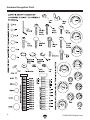
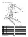
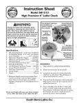
Engine Crane Breakdown (G8713) 110 127 120 126 126 117 116 119 120 111 124 126 125 121 120 123 109 106 105 105 115 117 120 126 112 114 108 113 107 101 102 120126 125 121 103 118 122 126 120 102-1 118 125 121 121 121 125 104 122 125 102-1 REF PART # DESCRIPTION REF PART # DESCRIPTION 101 102 102-1 103 104 105 106 107 108 109 110 111 112 113 P8713101 P8713102 P8713102-1 P8713103 P8713104 P8713105 P8713106 P8713107 P8712008 P8713109 P8713110 P8713111 P8713112 PB100M REAR SUPPORT REAR LEG W/SWIVEL CASTER SWIVEL CASTER INTERMEDIATE LEG FRONT LEG EXTENSION W/CASTER SUPPORT STRAP 8 TON HYDRAULIC RAM PUMP HANDLE HOOK & CHAIN ASSEMBLY MAIN SUPPORT POST BOOM BOOM EXTENSION EXTENSION SUPPORT HEX BOLT M14-2 X 100 114 115 116 117 118 119 120 121 122 123 124 125 126 127 PB174M PB98M PB176M PB133M PB138M PN17M PN13M PN32M PB98M PB133M PB175M PW10M PW08M PW13M HEX BOLT M14-2 X 120 HEX BOLT M14-2 X 80 HEX BOLT M20-2.5 X 120 HEX BOLT M16-2 X 90 HEX BOLT M16-2 X 100 HEX NUT M20-1.5 HEX NUT M16-2 HEX NUT M14-2 HEX BOLT M14-2 X 80 HEX BOLT M16-2 X 90 HEX BOLT M16-2 X 110 FLAT WASHER 14MM FLAT WASHER 16MM FLAT WASHER 20MM G7812/G7813 Engine Crane -13- Buy Direct and Save with Grizzly® – Trusted, Proven and a Great Value! Visit Our Website Today And Discover Why Grizzly® Is The Industry Leader! • SECURE ORDERING • ORDERS SHIPPED WITHIN 24 HOURS • E-MAIL RESPONSE WITHIN ONE HOUR -OR- Call Today For A FREE Full Color Catalog