1
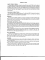
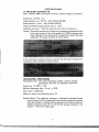
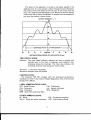
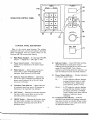
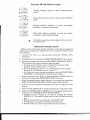
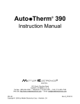
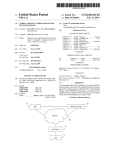
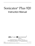
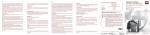
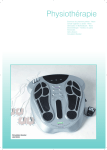
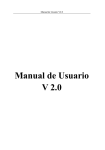
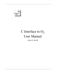
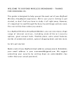
I A UAL . .. .' . ' SONICATOR 706 FCC Frequency In terferen ce Statem ent Wa rning: This equip m ent gener a tes and u s es ra dio fr equency energy and , if not installed and operated in s trict accor ance with the manufacturer's instructions, m ay cau se radio frequ ency interfer ence. Notice 1: This eq u ip m en t has b een verified to comply with the s p ecificati on s in Part 18 of FCC Ru les , which are designed to p r ovi d e rea s onable p rotection against radio frequency interference. How ver , ther e is no guarantee tha t interference will n ot occur in a p articu lar ins talla ti on . Notice 2: If this equipment is foun d to be the sou r ce of radio frequency interferen ce , which can b e determined by turning th equ ip m en t off and on, the user s h ou ld try to correct the interfer ence by one or more of the following measures: • Reorient the r eceivin g antenna (as applicable). • Relocate the Sonicator with r espect to the r eceiver. • Move th e Sonicator away from the receiver. • Plu g the Sonica tor into a different ou tlet than the receiver. • If n eces s ary, the u s er s h ou l con s u lt with the dealer or manufactur er for a d dition al suggestions . (Th e user may find FCC's "In terfer en ce Handbook" h lp fu l. It is available from the U.S. Government Prin ting Office, Wash ington , D.C. 204 02, Stock No. 004-00 0-00450-7.) Notice 3 : Th e m anufa cturer is not responsible for any interference caused by u nauthorized m odification to this equipment. Mettler Electronics Cor p . 1333 S . Claudina St. An aheim , CA 9 2805 Toll Free: (80 0 ) 854-9 3 0 5 Or (71 4 ) 53 3- 2 2 2 1 LIMITED WARRANTY This Product is warranted against defects in materials and workmanship for a period of one year from the date of purchase. During the warranty period Mettler Electronics Corp. will, at its discretion, either repair or replace the Product without charge for these types of defects. For service under this warranty, the Product must be returned within the warranty period to Mettler Electronics Corp. Shipping charges to and from Mettler Electronics Corp. under this warranty must be paid by the buyer. The buyer must also include a copy of the sales receipt or other proof of the date of purchase. If the Product is returned without proof of the date of purchase, it will be serviced as an out-of-warranty product at Mettler Electronics Corp.'s prevailing service rates. This warranty shall not be effective unless the Warranty Registration card included with the Product is returned to Mettler Electronics Corp. within thirty (30) days of the date of purchase. Alteration or misuse or neglect of the Product voids the warranty. Except as specifically set forth above, Mettler Electronics Corp. makes no warranties, expressed or implied, including without limitation any implied warranty of merchantability or fitness for a particular purpose, with respect to the Product. If any implied warranties apply as a matter of law, they are limited in duration to one year. Mettler Electronics Corp. shall not be liable for any indirect, special, consequential or incidental damages resulting from any defect in or use of the Product. Any suit brought by the buyer relating to this warranty must be commenced within one year from the date any claim arises and must be brought only in the State or Federal courts located in Orange County, California. Some states do not allow limitations on how long an implied warranty lasts, or the exclusion or limitation of incidental or consequential damages, so the above limitations or exclusions may not apply to the buyer. This warranty gives the buyer specific legal rights, and the buyer may also have other rights which vary from state to state. Copyright © 1986 by Mellier Electronics - Anaheim, CA TABLE OF CONTENTS Table of Contents ii Introduction 1 Safety Precautions Cleaning Instrucitons Guarantee Shipping Unpacking and Installation Wall Mounting Caution 2&3 Specifications Control Panel Description 4 Operating Instructions 5 Operator Troubleshooting Guide " ." General Application Information " 6 7 About Ultrasound Neurotrophic Approach Output Levels Continuous and Pulsed Waves Combination Therapy Phonophoresis Common Conditions Encountered in Athletics Treated by Ultrasound as an Adjunctive Therapy List of General Conditions Treated by Ultrasound as an Adjunctive Therapy Contraindications to Ultrasonic Therapy References ii INTRODUCTION SAFETY PRECAUTIONS: This unit operates with high voltages. Servicing of the Sonicator ME 706 should be referred to qualified service technicians or returned directly to the factory. To assure continued compliance with FDA, 21 CFR 1050.10 standards, the ME 706 should be factory calibrated and safety tested at least once each year. Mettler Electronics recommends that all service work be performed at the factory. However, a service manual can be obtained by writing the factory for those who are qualified to service the device and are fully aware of their responsibilities. CLEANING INSTRUCTIONS: To clean the molded plastic enclosure of the Sonicator ME 706 generator housing or applicator handle, use a mild detergent with a damp soft cloth. Use of any other cleaning agent or solvent is not warranted or recommended. SHIPPING: The instrument is shipped complete in one carton containing the unit itself, a wallmounting plate with three screws, guarantee card, operating instructions and one tube of Sonigel coupling agent. We recommend that you retain the shipping carton in the event you need to return the unit for factory servicing. UNPACKING AND INSTALLATION: Upon receipt of the unit, check for visible and hidden damage. If any damage is apparent upon opening the case, hold all shipping materials including the case and call the shipping agency which delivered the unit. They are responsible for all damage in transit; therefore, all claims should be fileddirectly with them. The factory will not be responsible for any damage in shipment, nor allow any adjustment unless proper formal claim has been filed by the receiver against the carrier. The unit operates on 120 volts, 60 hertz alternating current. (Other voltages are available.) Unless your voltage and frequency are as above, DO NOT CONNECT THE UNIT TO YOUR SUPPLY. If only direct current (DC) is available use a converter that provides 120 volts AC, 60 hertz with a capacity of 100 watts. WALL MOUNTING: To fasten the mounting plate on a wooden surface, use the three screws included with the unit. On a dry wall or plaster surface, use two "well-nuts". Position the plate with the slot facing upward and angled out from the wall. Lower the mounting screw (located on the upper back of the unit) firmly into the mounting plate slot. CAUTION: Federal law restricts this device to sale or on the order of a physician, dentist, veterinarian, or any other practitioner licensed by the law of the state in which he practices to use or order the use of this device. Use of controls or adjustments or performance of procedures other than those specified herein may result in hazardous exposure to ultrasonic energy. Electric treatment tables or whirlpools which may come in contact with the patient during a treatment with the Sonicator ME 706, should be adequately grounded and safety tested to insure safe operation with the Sonicator ME 706. 1 SPECIFICATIONS ULTRASONIC GENERATOR: Input: 120VAC, 60Hz, 0.5 amperes maximum. (Other voltages are available.) Frequency: 1.0 MHz ± 5% Pulse repetition rate: 100 Hz ± 20% (PULSE MODE) Pulse duration: 2 msec ± 20% (PULSE MODE) Temporal Peak/Average intensity ratio: 5 ± 20% Indication accuracy: ± 20% (for any level above 10% of maximum.) Output: The output waveform in continuous or pulsed as programmed by the front panel control. In the pulse mode the 1.0 MHz is square wave pulse modulated. The power level is adjusted by varying the pulse amplitude. The pulse waveform is shown below: In the continuous mode the power is on all the time the timer is running. The continuous mode waveform is shown below: i , I ULTRASONIC APPLICATOR: Piezoelectric disc: The output transducer utilizes a barium titanate piezoelectric disc with an especially coated face. Frequency: 1.0 MHz ± 5% Effective Radiating Area: 10 em" ± 20% Beam type: Collimating Maximum beam non-uniformity ratio: 6:1 Spatial Pattern: The applicator produces a collimated (cylindrical) beam with an area of 10 cm 2 as measured 5 mm from the ceramic disc surface when the radiation is emitted into the equivalent of an infinite medium of distilled, degassed water 300 C, and with line voltage variations in the range of ± 10% of the rated value. 2 The beam of the applicator is circular in all planes parallel to the applicator face. If a cross section is taken through the axis of the beam, the pattern varies with distance from the face. A few inches from the face, It is a single smooth bell-shaped curve. Nearer the face the pattern varies more due to phase cancellations. A sample curve as measured 5 mm from the surface is shown below. OUTPUT INTENSITY - % 100 . 40 20 0 cm 2 APPLICATOR - - -..... :. ...- - - DISTANCE FOR A 10 20 15 10 5 CENTER 5 10 15 20 DISTANCE FROM CENTER OF APPLICATOR IN mm TREATMENT TIMER: Indicator: The timer digital indicator indicates set time in minutes and seconds prior to the start of treatment and treatment time remaining during the treatment. The timer also indicates the remaining treatment time during the "hold" period. Accuracy: ± 1 second at all settings Maximum treatment time: 29 minutes CERTIFICATION: The Sonicator ME 706 complies with the ultrasound performance standards set forth in the Code of Federal Regulations, Title 21 (Food and Drugs), Part 1050.10. LABEL ABBREVIATIONS USED: SIN - Serial Number Coll - Collimating A Gen - Generator Freq - Frequency BNR - Beam Non-uniformity Ratio ern- - Square centimeter MHz - Megahertz OTHER ABBREVIATIONS: W - Watts W/cm 2 - Watts per square centimeter CW - Continuous-waveform LED - Light Emitting Diode 3 ,.......--1·IMER---., Minutes (10) POWER (9) Seconds (4) I I ~ 001%21 0 SONICATOR CONTROL PANEL (3) o [ cw IlpUlSf) 0 (8) (2) (8) CONTROL PANEL DESCRIPTION ON OFF D Refer to the control panel drawing. The number associated with each control and indicator described below corresponds with the number shown on the Sonicator ME 706 control panel drawing. (1) (1) Main Power Control - A rocker-type ON/OFF selector - depress left = ON, right = OFF. (2) (8) Indicator Lights - Green LED (light emitting Power Level Control - Determines the output level as indicated on the power output indicator. diode) indicators for each power output indicator function (Wand W/cm 2) and for each mode (CW and PULSE). Two of these indicators are lit during Sonicator operation, one each for indicator function and mode selected. (3) Mode Selector - Selects either continuous wave (CW), or pulse-modulated (PULSE) operation. Initial turn-on is in CW mode. .(9) (4) Indicator Function Selector - Determines one of two types of indication provided by the power output indicator (W or W/cm2 ) . Initial turn-on is in W mode. Power Output Indicator - Provides indication of ultrasonic power output. W (5) Treatment Time Selector - Allows selection In CW mode the indicator displays average ultrasonic power in watts. In PULSE mode it displays peak pulse ultrasonic power in watts. W/cm 2 of treatment times from zero to 29 minutes as indicated on the treatment time indicator. (6) In CW mode the indicator displays average effective intensity in watts per square centimeter. In PULSE mode it displays peak pulse effective intensity in watts per square centimeter. (10) Treatment Time Indicator - Indicates treatment time selected and displays remaining time when the timer is activated. (Power output automatically drops to zero watts at the end of the selected treatment time.) 'GO' Switch - Selecting this function activates the timer (which counts down in one second intervals) and the ultrasonic power. (7) 'HOLD' Switch - Selecting this function stops the timer (which remains in a hold state at the indicated time remaining) and turns off the ultrasonic power. 4 - ~ ~---------------------------. Sonicator ME 706 Indicator Lights ®~I~o Average ultrasonic power mode. ®[~~] PULSEI° ®[~]~2Io O~I~® Average effective intensity in watts centimeter, continuous-wave mode. ®~~JULSEIO O~I~® per square Peak pulse effective intensity in watts per square centimeter, pulse-modulated mode. O[ cw IlpULSEI® e .. watts, continuous-wave Peak pulse ultrasonic power in watts, pulse-modulated mode. °EJlpULSEI® .. In This symbol (as used above) indicates lighted LED's at each of the four output settings. OPERATING INSTRUCTIONS Refer to the control panel drawing. Numbers in the following operating procedures, for example (1), indicate the control or indicator number shown in the drawing. 1. Connect the unit to an appropriately grounded 120VAC, 60Hz receptacle. 2. Energize the unit by pressing the MAIN POWER SWITCH (1) to the left. 3. Enter the treatment time using the TREATMENT TIME SELECTOR (5). The treatment time must be entered using two digits. a. For times up to 9 minutes, enter '0' followed by the second digit. Example: For 9 minutes, enter a '0' then a '9'. b. For 10 to 29 minutes, enter a '1' or '2' followed by the second digit. Example: For 15 minutes, enter a '1' then a'S'. c. If an incorrect time is entered accidentally, cycle the MAIN POWER CONTROL (1) and reselect the desired treatment time. 4. Select continuous-wave (CW) or pulse-modulated (PULSE) mode by pressing the appropriate MODE SELECTOR (3) function. 5. Select the desired power output indication by pressing the appropriate INDICATOR FUNCTION SELECTOR (4) switch (W or W/cm 2) . 6. Coat the area to be treated with Sonigel and couple the applicator to the patient. 7. Press the 'GO' SWITCH (6) to initiate treatment time and power output. 8. Adjust the POWER LEVEL CONTROL (2) to the desired output level as indicated on the POWER OUTPUT INDICATOR (9). a. Treatment can be stopped at any time by pressing the 'HOLD' SWITCH (7). The power will stop and the timer will hold its running time. b. Restart the treatment by pressing the 'GO' SWITCH (6). c. A single long buzz sounds at the end of treatment time. d. Several short buzzes sound if treatment time is interrupted. 5 OPERATOR TROUBLESHOOTING GUIDE Action/Check Sympton 1. No lights when MAIN POWER SWITCH is depressed. Line cord properly connected to AC outlet. 2. TIMER indicates a number between 01 and 29 (or 88.88, 98.88, or 64.88), but the unit will not start when GO is pressed. Cycle the MAIN POWER SWITCH (OFF & ON) and program the TIMER with TWO digits as per the operating instructions (page 5). 3. After starting, the unit stops with the TREATMENT TIME INDICA TOR showing time left and the buzzer sounds five short buzzes. Check for adequate transducer coupling and use of recom mended couplant such as Sonigel, then press the GO SWITCH. (Read the paragraph below.) The Sonicator ME 706 has a special feature, a no-load sensor, that limits and cuts off power automatically if contact between the transducer and the patient's skin is interrupted for a period of time. The buzzer will buzz for several (about five) short buzzes when the automatic no-load sensor shuts off the unit. This feature adds another dimension of protection against excessive heat build-up on the ceramic disc. Initial dis-contact produces a drop in the amount of current flowing to the disc and within about 3 to 5 seconds, energy is totally cut off. Should this feature activate frequently, it may be an indication that coupling is either insufficient in quantity, or inefficient in performance. The lack of good coupling may be caused by not using a good coupling agent such as Sonigel, not using sufficient amounts of the coupling agent (you cannot use too much), or contact with a very small area such as at the extremities (hands and feet) without the use of copious amounts of a coupling agent. When treating an area such as a hand or foot, you may treat under water as indicated in the illustration on page 8. You may also use a cushion filled with the couplant to treat an irregular surface. Selecting the proper couplant insures proper energy transmission, thereby enhancing the efficiency of treatment while discouraging energy reflection back to the disc, causing eventual damage and possible depolarization. NOTE: If unable to resolve a problem with the unit, contact your dealer, or communicate directly with the manufacturer. 6 r GENERAL APPLICATION INFORMATION ABOUT ULTRASOUND: Ultrasound is a form of acoustical vibration occuring at frequencies too high to be perceived by the human ear. The limit for the audible range is at about 20 KHz. Frequencies above this level are considered ultrasound. The range from 700 KHz to 1.1 MHz appeared during early investigative work, to be best suited to clinical applications. Most domestic units operate at frequencies within this range. The physics of ultrasound and audible sound bear certain similarities with frequency being the exception. Both travel as longitudinal compressed waves through a conducting medium. Ultrasound waves can be propagated in a gaseous, liquid, or solid medium, but not in air. High frequency sound waves are formed by areas of compression and rarefaction of the molecules. It is not within the scope of this manual to discuss this subject in depth. The reader can choose his own levelof familiarity through reading the articles offered as references. However, it is important to know ultra sound exhibits certain beaming proper ties: It can be reflected, refracted, scattered and absorbed. In passing through media, it is attenuated and the absorbed energy is transformed into heat. The attenuation coefficient for longitudinal waves in liquid and soft tissues is high, producing the phenomenon at bone surfaces known as selective heating. Clinical ultrasound is produced through the reverse piezoelectric effect. Electricity is carried from a radio frequency source to an electrode in contact with the surface of an especially cut crystal. The electrical charges applied to the crystal surface produce mechanical vibrations, or the so-called reverse piezoelectric effect. Ultrasound waves need a medium for their transmission and that is accomplished by using a proper coupling agent. This coupling layer between the transducer and body surface should assist in the propagation of the mechanical vibrations and prevent loss of transmission. 7 The crystal may be natural or synthetic and may be salt, quartz, poly crystalline or ceramic. When this crystal is in resonance with the driving oscillator, optimum conversion from electrical to mechanical energy is achieved. A disadvantage of quartz is that it requires extremely high voltages of the applicator (3000 - 4000V) to energize it for an intensity of 3 W/cm 2 • Ceramic crystals require less (30 - 40V), thus allowing use of longer, thinner, and more flexible coaxial cables. The Sonicator ME 706 uses a barium titanate cobalt ceramic. Ultrasonic energy is expressed in watts (W), or watts per square centimeter (W/crn''). Average intensity is obtained by measuring the total output of the applicator (in watts) and then dividing it by the size of the effective radiating area of the applicator. The effective radiating area is different from the overall dimension of the applicator face. Once the coupling agent is applied to the body surface, the applicator placed in contact and the desired output selected in total watts, or watts per square centimeter, the technique of applicaton is by means of circular or stroking movement. In the circular method, the soundhead of the applicator is moved in slow and circular overlapping movements. In the stroking, or "paint brush" method, slow to-and-fro strokes are used, again with slight overlapping. Motion with either technique should be slow enough to insure proper energy absorption yet fast enough to eliminate excessive amounts of absorption which could produce periosteal pain. On occasion, irregular surfaces of the body are treated (hands) and may offer a poor surface for proper soundhead contact. The underwater technique may be used for these applications. The part to-be-treated and the soundhead are submerged in water and the soundhead is moved over the area, keeping the head Y2 to 1 inch away from the area of treatment. As air bubbles appear on the surface of the soundhead they should be wiped away to insure proper transmission of energy. 8 I 1 r NEUROTROPHIC APPROACH: It is most important that the neurotrophic (nerve root) approach be used because it generally produces an analgesic effect on the sensory nerves to the involved tissues. Most physicians recommend that the area of involvement be treated first. A strip slightly wider than the diameter of the applicator should be treated in the cervical section. In the dorsal region, the area should be about two inches wide. The strip should be increased from two to four inches as you render treatment through the lumbar and sacral areas. These strips should reach to, but not include, the spinal process. The first area is from the cervical through the first dorsal. This area controls nerve roots leading to the lower neck, upper section of the back, shoulders, arms, hands and fingers. The second is the thoracic area, which extends from the first dorsal through the first lumbar. This section controls the upper trunk of the body. The third and last is the lower lumbar and sacral, starting from the first lumbar through the coccyx. This section controls the nerve roots to the hips and legs. (The above is not an exact outline, but it should suffice for ultrasonic treatment. Since such a large group of nerve roots are always treated at one time, care need not be taken to locate the specific nerve roots that are indicated.) POSTERIOR ANTERIOR 3W55M 3104W =-"""'--1 C,rvlc.1 5M 5W55M 5wa 5M 4W 5M RibIfI I 5W 5M Dorll' 3104W 410 5W 5M 6wa 5M 5M lumb.r IIl;r.1 6W a 5M 5W 5M 6Wa 5M 3 to 4W 5M 5W 5M 5WJ-------/T 5M L-_---I+ 5wa5M 4105W 5M t===f-4wa 5M -~-=_-----J ~~. 4W POSTERIOR TREATMENT Note: W=lotal watts output. and M=minutes (Where not marked. use output level shown on the anterior chart.) An average of treatment lime and output levels used by present day therapists. 9 ;, r Dosage in total watts, or watts per square centimeter, and treatment time may vary from patient-to-patient and with areas to be treated. Generally, the transducer (applicator) is moved in a slow, steady rotary or stroking motion at the approximate rate of 24 square inches (l55cm2 ) per minute. Most treatments require repetition over this area for a period of five minutes. For a few hours duration after ultrasonic treatment, the pain may increase. If this occurs, treatments should be continued but with a slight reduction in time and power. Frequency of treatment varies from once daily to three times per week. OUTPUT LEVELS: The differences between transducers of varying radiating areas are shown below. The chart is a calculation of power output for three transducer crystals with different radiating areas. Intensity Setting (W/cm2 ) Crystal Effective Radiating Area Effective Watts Produced 1.5 1.5 1.5 5 ern 6 em? 7.5 W 9.0W 15.0 W 10 ern You will note, though the intensity setting remained constant, the amount of energy delivered varied ... appreciably. We caution you to consider this since units of different manufacture are available in many departments. If watts per square centimeter is used as the prescribed intensity setting, the effective watts delivered will not remain constant. For this reason, we suggest that using average power, or WATTS, as the intensity setting insures the amount delivered by any unit and any sized crystal remains constant as desired. 10 ------------------------- .... I [ ( CONTINUOUS AND PULSED WAVES: Ultrasound may be applied in either continuous or pulsed waveform. Advocates of pulsed beam applications suggest the approach reduces the thermal effects while accenting the mechanical. Wulff in his paper titled, "Reduction of Thermic Effect of Ultrasound Dosages by the Use of Pulsed Ultrasound Energy" reported, ". . . the use of pulsed ultrasound energy permits accurately controlled reduction of total ultrasound intensities employed in therapy." He recommended the use of rectangular pulses and stated, "The biologic response reactions of the sonated tissue seems to continue during the sound free intervals provided that a ratio between pulse duration and free interval of 1:4 is maintained." The ME 706 provides both continuous and pulse wave capabilities. Continuous is a 100% duty cycle and an unmodulatd wave which orginates from a filtered DC power source. The pulse setting has a pulse frequency of 100Hz with a pulse width of 2 milliseconds and 8 milliseconds between pulses. On time to total time is 1:5. The duty cycle is 20%and on time to off time is a ratio of 1:4. In the pulse mode, the meter reads peak power. COMBINATION THERAPY: Combination therapy may be performed by plugging the Sys·Stim@ muscle stimulator active lead wire (black and negative) into the black col lared phone jack located on the bottom of the Sonicator 705/706. The phone jack is identified by the symbol A When output is generated by the stimulator, it will be passed to the metal ring on the transducer head by means of this connection. The timer on the Sonicator will control the length of time ultrasound is delivered. The Sys" Stirn timer is placed into timer bypass during combination therapy. When the selected time has elapsed on the Sonicator, indicating the end of treatment, press hold on the Sys" Stirn to stop stimulation output through the transducer. 11 "TRIGGER-POINTS" are small areas of localized sensiti vity and pain found in muscles and connective tissue. They may be produced by trauma, can be a result of chronic strain or may be developed as a result of stress from functional daily activities or postural habits. Though local in nature, reports in the literature indicate the discomfort may be referred through the autonomic nerve fibers to other areas of the body (so-called "referred pain"). electrical currents. It has been suggested the combina tion of electrical stimulation and ultrasound is beneficial in both locating and treating those involved areas. A tetanizing current within comfortable intensity range of the patient is normally used for both location and treatment, offering "massage-like" contraction to the muscles where it is applied. Articles of reference are listed. The application is widespread and successful treatments have been reported in both acute and chronic conditions. These areas may be palpated with finger-tip pressure, located by using the eraser end of a pencil, or by means of MASSETEH ZDNE REFFRRf!J PAIN ~- SCALENl iRA,PEZiU~) THtGGER POiNT lNFHASPINATUS MULPflDlJS 1- GUJTEUS MiNIMUS MIDDLE F1NCiER EXTENSOR vxsrus MEDIAUS PEnONEUS LONG EXTENSORS • C.4PiTlS S TERNOMA5 roiu U:::VAlOR SCAPULAE POSTERIOR CERV'CAL ADDUCTOR POLllCUS HRST INTEROSSEOuS REFERENCES: Travel, J. and Rinzier, S.H. "The Myofascial Genesis of Pain," POSTGRADUATE MEDICINE, Vol. II, No.5, May, 1952. ADDU(:TO~t LONGUS /\8DUCTOn HALLUC;;::; Sola, A.E. "Myofascial Trigger Point Pain in the Neck and Shoulder Girdle," NORTHWEST MEDICINE, Vol. 54, pp. 980-984 September, 1955. 12 ""'" ---------------------------------------- ..... I PHONOPHORESIS: Phonophoresis, or sonophoresis, has been described as the use of ultrasonic waves for the percutaneous transport of drugs. Since the technique was first introduced, it has grown in popularity and to many authors, seems to be a method of choice for driving topically applied medication into deep layers of soft tissues. The effect of ultrasound energy in increasing membrane permeability appears to be part of the reason for improvement in pain relief. The coupling material contains medication in variable strengths from 0.5 to 10%- and both the moving and stationary head techniques have been used. According to the literature, settings of. 1 - 2 W/ ern- for moving head and 0.1 0.2 W/cm 2 for stationary techniques have been applied. COMMON CONDITIONS ENCOUNTERED IN ATHLETICS TREATED BY ULTRASOUND AS AN ADJUNCTIVE THERAPY Charley horse, contusions, edema, trauma, synovitis, adhesions, myositis ossificans, pulled muscles, sprains, neuritis, sacro-iliac strain, wry neck, bursitis, sciatica, shin splints, pulled tendons, strains, arthritis, stone bruise, tenosynovitis, scar tissue, dislocations, sacro-lumbar strain, separations. LIST OF GENERAL CONDITIONS TREATED BY ULTRASOUND AS AN ADJUNCTIVE THERAPY Arthrosis (large articulations), (small articulations), coccygodynia, lumbago, neuralgia intercostal, periostotis, sciatica, Sudeck's Atrophy, coxitis, myalgia, neuritis, plantar warts, sinusitis frontal, syndrome scalenus, bursitis, Dupuytren's Contracture, myelitis, osteitis, postoperative pain, radiculitis, sinusitis maxillary, tenovaginitis, claudication intermittent, herpes zoster, neuralgia, periarthritis humeroscapular, Raynaud's diseases, Spondylitis Deforman's, periarthritis chronic, stump (phantom pains). CONTRAINDICATIONS TO ULTRASOUND THERAPY Over malignant tumors, over epiphysis of growing bone, over acute infections, acute thrombophlebitis or phlebothrombosis, over pregnant uterus, over the eyeball, over areas of impaired sensation, over brain or bulbar area of spinal cord, over areas of inadequate circulation, over the heart, over reproductive organs, in patients with hemorrhagic diatheses. In addition, authors have recommended special precautions to dosage when an area of the spinal cord is to be treated following a laminectomy. It has also been reported that ultrasound should not be given over pacemakers or over pacemaker leads. 13 r REFERENCES: We recognize the reader's interest in clinical ultrasound may extend beyond the level of information we are able to provide in this manual. To assist you in your search, we are including the titles of text books and selected articles. Each of them in turn will offer additional sources for reference. 1. Griffin, J.E. & Karselis, T.e.: Physical Agents for Physical Therapists, e.C. Thomas, Springfield, Ill., 1978, pp. 225-227. 2. Griffin, J.E. & Touchstone, J.: Effects of Ultrasonic Frequency of Phono phoresis of Cortisol into Swine Tissues, Am. J. Phys, Med. 51:62, 1972. 3. Kleinkort, J.A. & Wood, F.: Phonophoresis With One Per Cent Versus Ten Percent Hydrocortisone. Phys. Ther., 55:1320, 1975. 4. Travel, J. and Rinzier, S.H., "The Myofascial Genesis of Pain," POST GRADUATE MEDICINE, Vol. II, No.5. May, 1952. 5. Sola, A.E., "Myofascial Trigger Point Pain in the Neck and Shoulder Girdle," NORTHWEST MEDICINE, Vol. 54, pp, 980-984 Sept., 1955. TEXT BOOKS - 1. Handbook of Physical Medicine and Rehabilitation, second edition, F.H. Krusen, M.D., F.J. Kottke, M.D., P.M. Ellwood, Jr. M.D., W.B. Saunders Co., Phila. 2. Physical Agents for Physical Therapists, Griffin, J.E. and Karselis, T.e., e.C. Thomas, Springfield, Ill., pp. 225-227. ARTICLES - 1. Advantages and Limitations of Ultrasonics in Medicine, H.P. Schwan, Ph.D. & E.L. Carstensen, M.S., JAMA 5.52 Vol. 149, PP 121-125. 2. Non-surgical Management of the Pain-Dysfunction Syndrome - W.H. Bell, D.D.S., JADA, Vol. 79, July 69. 3. Interaction of Ultrasound & Biological Tissues, Workshop Proceedings, Batalle Memorial Inst., U.S. Dept. of Health, Sept. 72. In addition, we have a packet of information available which includes selected reprints, ultrasound technique and trigger point charts, etc. For your free copy, write: Educational Dept., Mettler Electronics Corp., 1333 S. Claudina St., Anaheim, California 92805 14 Printed in U.S.A. IR6-17 1~95 USER A UAL N \ . ET T L ER : E L E C T R O N IC S il!i c orp . Additional copies of this chart are available upon request by writi ng: Mettler Electronics Corp. 1333 So. Claudina St., Anaheim, Calif. 92805 U.S.A. Telephone: (714) 533-2221 • (800) 854-9305 U.S.A. FAX (714) 635-7539