1
1998-1999
MAINTENANCE
SERVICE
MANUAL
DS GOLF CARS
GASOLINE/ELECTRIC
MANUAL NUMBER 101968401
EDITION CODE 0199B0312A
FORWARD
Club Car golf cars are designed and built to provide maximum efficiency and performance. However, proper
maintenance and repair is essential for achieving maximum service life and continued safe and reliable operation. This maintenance and service manual provides detailed procedures for the maintenance and repair of
those components that are common to all Club Car DS Golf Cars, and should be used in conjunction with the
appropriate maintenance and service supplement. The supplement will provide maintenance and repair procedures for those components specific to a particular type of vehicle. If you do not have the appropriate supplement for your vehicle(s), you may obtain one of the following from your Club Car distributor:
1998/1999 PowerDrive System 48 Vehicle Maintenance & Service Supplement
Publication Part No. 101968404
1998/1999 PowerDrive Plus Vehicle Maintenance & Service Supplement
Publication Part No. 101968405
1998/1999 V-Glide 36-Volt Vehicle Maintenance & Service Supplement
Publication Part No. 101968406
1998/1999 FE 290 Gasoline Vehicle Maintenance & Service Supplement
Publication Part No. 101968407
This manual and the supplement should be read prior to servicing the vehicle. The procedures provided must
be properly implemented, and the CAUTION, WARNING, and DANGER statements must be heeded.
This manual was written for the vehicle mechanic who already possesses basic knowledge and skills in electrical and mechanical repair. If the mechanic does not have such basic knowledge and skills, attempted service or repairs to the vehicle may render it unsafe. For this reason, we advise that all repairs and/or service
be performed by an authorized Club Car distributor’s/dealer’s representative or by a Club Car factory trained
technician.
It is the policy of Club Car, Inc. to assist its distributors and dealers in continually updating their service
knowledge and facilities so they can provide prompt and efficient service for vehicle owners. Regional technical representatives, golf car service seminars, periodic service bulletins, maintenance and service manuals,
and other service publications also represent Club Car’s continuing commitment to customer support.
This service manual, used in conjunction with the appropriate supplement, covers all aspects of typical DS
Golf Car service. However, unique situations do sometimes arise when servicing a golf car. If it appears that
a service question is not answered in this manual or the supplement, you may write to us at: Club Car, Inc.;
P.O. Box 204658; Augusta, GA 30917; Attention: Technical Services, or contact a Club Car Technical Service
representative at (706) 863-3000, extension 3580.
©1999, 2012 Club Car, Inc.
Club Car, Armorflex, PowerDrive, PowerDrive Plus,
and Tranquility are registered trademarks of Club Car, Inc.
This manual effective August 1, 1998
1998/1999 DS Golf Car Maintenance and Service Manual
Page i
WARNING
• READ SECTION 1 - SAFETY - BEFORE ATTEMPTING ANY SERVICE ON THIS VEHICLE.
• BEFORE SERVICING VEHICLE, READ COMPLETE SECTION(S) AND ANY REFERENCED
INFORMATION RELEVANT TO SERVICE OR REPAIR TO BE PERFORMED.
NOTE
• THIS MANUAL REPRESENTS THE MOST CURRENT INFORMATION AT TIME OF
PUBLICATION. CLUB CAR, INC. IS CONTINUALLY WORKING TO FURTHER IMPROVE OUR
VEHICLES AND OTHER PRODUCTS. THESE IMPROVEMENTS MAY AFFECT SERVICING
PROCEDURES. ANY MODIFICATION AND/OR SIGNIFICANT CHANGE IN SPECIFICATIONS OR
PROCEDURES WILL BE FORWARDED TO ALL CLUB CAR DISTRIBUTORS AND DEALERS AND
WILL, WHEN APPLICABLE, APPEAR IN FUTURE EDITIONS OF THIS MANUAL.
• DAMAGE TO A VEHICLE OR COMPONENT THEREOF NOT RESULTING FROM A DEFECT OR
WHICH OCCURS DUE TO UNREASONABLE OR UNINTENDED USE, OVERLOADING, ABUSE,
OR NEGLECT (INCLUDING FAILURE TO PROVIDE REASONABLE OR NECESSARY
MAINTENANCE AS INSTRUCTED IN THE VEHICLE OWNER’S MANUAL), ACCIDENT OR
ALTERATION,
INCLUDING
INCREASING
VEHICLE
SPEED
BEYOND
FACTORY
SPECIFICATIONS OR MODIFICATIONS WHICH AFFECT THE STABILITY OF THE VEHICLE OR
THE OPERATION THEREOF, WILL VOID THE WARRANTY.
• CLUB CAR, INC. RESERVES THE RIGHT TO CHANGE SPECIFICATIONS AND DESIGNS AT
ANY TIME WITHOUT NOTICE AND WITHOUT INCURRING ANY OBLIGATION OR LIABILITY
WHATSOEVER.
• THERE ARE NO WARRANTIES EXPRESSED OR IMPLIED IN THIS MANUAL. SEE THE LIMITED
WARRANTY FOUND IN THE VEHICLE OWNER’S MANUAL OR WRITE TO CLUB CAR, INC.
Page ii
1998/1999 DS Golf Car Maintenance and Service Manual
CONTENTS
SAFETY
SECTION
General Warning ...............................................................................................................................
VEHICLE SPECIFICATIONS
1-1
SECTION
General Information ..........................................................................................................................
GENERAL INFORMATION
Model Identification ...........................................................................................................................
3-1
Safety Committee .............................................................................................................................
3-1
Pre-Operation Checklist ....................................................................................................................
3-2
Controls ............................................................................................................................................
3-3
Driving Instructions ...........................................................................................................................
3-9
Towing ...............................................................................................................................................
3-11
Transporting on a Trailer ...................................................................................................................
3-11
Storage - Gasoline Vehicle ...............................................................................................................
3-12
Storage - Electric Vehicle ..................................................................................................................
3-13
SECTION
General Information ..........................................................................................................................
4-2
Front and Rear Body Repair .............................................................................................................
4-2
Seat ..................................................................................................................................................
4-4
Front Body ........................................................................................................................................
4-4
Rear Body .........................................................................................................................................
4-6
Floormat ............................................................................................................................................
4-8
ACCELERATOR AND BRAKE PEDAL GROUP
SECTION
General Information ..........................................................................................................................
5-1
Pedal Group Adjustment....................................................................................................................
5-2
Pedal Group Disassembly and Assembly .........................................................................................
5-8
WHEEL BRAKE ASSEMBLIES
SECTION
Removal and Cleaning of Wheel Brake Assemblies .........................................................................
6-3
Installing the Brake Shoes ................................................................................................................
6-5
Adjusting the Brakes .........................................................................................................................
6-8
Removal and Installation of Brake Assembly ....................................................................................
6-8
1998/1999 DS Golf Car Maintenance and Service Manual
2
2-1
SECTION
BODY AND TRIM
1
Page iii
3
4
5
6
STEERING AND FRONT SUSPENSION
SECTION
General Information - Steering...........................................................................................................
Steering Wheel .................................................................................................................................
Steering Column ...............................................................................................................................
Steering Adjustment ..........................................................................................................................
Rack and Pinion ................................................................................................................................
Tie Rod and Drag Link ......................................................................................................................
Front Suspension ..............................................................................................................................
Front Suspension Components ........................................................................................................
Front Wheel Bearings and Hubs .......................................................................................................
WHEELS AND TIRES
7-1
7-2
7-2
7-6
7-7
7-10
7-12
7-14
7-18
SECTION
General Information ...........................................................................................................................
8-1
Wheel Removal, Repair and Installation ...........................................................................................
8-2
REAR SUSPENSION
SECTION
General Information ..........................................................................................................................
Shock Absorbers ...............................................................................................................................
Leaf Springs ......................................................................................................................................
Page iv
1998/1999 DS Golf Car Maintenance and Service Manual
7
9-1
9-3
9-3
8
9
1
SECTION 1–SAFETY
To insure the safety of those servicing Club Car DS Golf Cars, and to protect the vehicles from possible damage resulting from improper service or maintenance, the procedures in this manual must be followed. It is
important to note that throughout this manual there are statements which are contained within boxes labeled
DANGER, WARNING, or CAUTION. These special statements relate to specific safety issues, and must be
read, understood, and heeded before proceeding with procedures. There are also boxes labeled NOTE,
which provide other essential service or maintenance information.
DANGER
• A DANGER INDICATES AN IMMEDIATE HAZARD WHICH WILL RESULT IN SEVERE
PERSONAL INJURY OR DEATH.
WARNING
• A WARNING INDICATES AN IMMEDIATE HAZARD WHICH COULD RESULT IN SEVERE
PERSONAL INJURY OR DEATH.
CAUTION
• A CAUTION INDICATES HAZARDS OR UNSAFE PRACTICES WHICH MAY RESULT IN
PRODUCT OR PROPERTY DAMAGE OR MINOR PERSONAL INJURY.
NOTE
• A NOTE PROVIDES
UNDERSTOOD.
KEY
INFORMATION
TO
MAKE
PROCEDURES
MORE
EASILY
GENERAL WARNING
The following safety procedures must be followed whenever the vehicle is being operated, repaired,
or serviced. Service technicians should become familiar with these general statements, which will be
found frequently throughout this manual. Also, other specific warnings appear throughout this manual and on the vehicle.
DANGER
• BATTERY - EXPLOSIVE GASES! DO NOT SMOKE. KEEP SPARKS AND FLAMES AWAY FROM
THE VEHICLE. VENTILATE WHEN CHARGING OR USING IN AN ENCLOSED SPACE. ALWAYS
WEAR A FULL FACE-SHIELD WHEN WORKING ON OR NEAR BATTERIES.
• BATTERY - POISON! CONTAINS ACID! CAUSES SEVERE BURNS. AVOID CONTACT WITH
SKIN, EYES, OR CLOTHING. ANTIDOTES:
- EXTERNAL: FLUSH WITH WATER. CALL A PHYSICIAN IMMEDIATELY.
- INTERNAL: DRINK LARGE QUANTITIES OF WATER. FOLLOW WITH MILK OF MAGNESIA
OR VEGETABLE OIL. CALL A PHYSICIAN IMMEDIATELY.
- EYES: FLUSH WITH WATER FOR FIFTEEN MINUTES. CALL A PHYSICIAN IMMEDIATELY.
1998/1999 DS Golf Car Maintenance and Service Manual
Page 1-1
1
SAFETY
General Warning
General Warning, Continued:
DANGER
• GASOLINE - FLAMMABLE! EXPLOSIVE! DO NOT SMOKE. KEEP SPARKS AND FLAMES
AWAY FROM VEHICLE AND SERVICE AREA. SERVICE ONLY IN A WELL-VENTILATED AREA.
• DO NOT OPERATE GASOLINE VEHICLE IN AN ENCLOSED AREA WITHOUT PROPER
VENTILATION. THE ENGINE PRODUCES CARBON MONOXIDE WHICH IS AN ODORLESS,
DEADLY POISON.
• A GOLF CAR WILL NOT PROVIDE PROTECTION FROM LIGHTNING, FLYING OBJECTS, OR
OTHER STORM RELATED HAZARDS. IF CAUGHT IN A STORM WHILE DRIVING A GOLF CAR,
EXIT THE VEHICLE AND SEEK SHELTER IN ACCORDANCE WITH APPLICABLE SAFETY
GUIDELINES FOR YOUR LOCATION.
WARNING
• ONLY TRAINED MECHANICS SHOULD REPAIR OR SERVICE THE VEHICLE. ANYONE DOING
EVEN SIMPLE REPAIRS OR SERVICE SHOULD HAVE KNOWLEDGE AND EXPERIENCE IN
ELECTRICAL AND MECHANICAL REPAIR.
• FOLLOW THE PROCEDURES EXACTLY AS STATED IN THIS MANUAL, AND HEED DANGER,
WARNING, AND CAUTION STATEMENTS LISTED IN THIS MANUAL AS WELL AS THOSE
AFFIXED TO THE VEHICLE.
• IMPROPER USE OF THE VEHICLE OR FAILURE TO PROPERLY MAINTAIN IT, COULD RESULT
IN DECREASED VEHICLE PERFORMANCE OR SEVERE PERSONAL INJURY.
• ANY MODIFICATION OR CHANGE TO THE VEHICLE WHICH AFFECTS THE STABILITY OR
HANDLING OF THE VEHICLE, OR INCREASES MAXIMUM VEHICLE SPEED BEYOND FACTORY
SPECIFICATIONS, COULD RESULT IN SEVERE PERSONAL INJURY OR DEATH.
• CHECK THE VEHICLE OWNER’S MANUAL FOR PROPER LOCATION OF ALL VEHICLE
WARNING DECALS AND MAKE SURE THAT THEY ARE IN PLACE AND ARE EASY TO READ.
• ALWAYS WEAR SAFETY GLASSES OR APPROVED EYE PROTECTION WHEN SERVICING THE
VEHICLE. WEAR A FULL FACE SHIELD WHEN WORKING WITH BATTERIES.
• DO NOT WEAR LOOSE CLOTHING. REMOVE JEWELRY SUCH AS RINGS, WATCHES, CHAINS,
ETC. BEFORE SERVICING VEHICLE.
• MOVING PARTS! DO NOT ATTEMPT TO SERVICE THE VEHICLE WHILE IT IS RUNNING.
• HOT! DO NOT ATTEMPT TO SERVICE HOT MOTOR, RESISTORS, ENGINE, OR EXHAUST
SYSTEMS. FAILURE TO HEED THIS WARNING COULD RESULT IN SEVERE BURNS.
• ALWAYS USE INSULATED TOOLS WHEN WORKING AROUND BATTERIES OR ELECTRICAL
CONNECTIONS.
• LIFT ONLY ONE END OF VEHICLE AT A TIME. BEFORE LIFTING, LOCK THE BRAKES AND
CHOCK THE WHEELS THAT REMAIN ON THE FLOOR. USE A SUITABLE LIFTING DEVICE
(CHAIN HOIST OR HYDRAULIC FLOOR JACK) WITH 1000 LBS. (454 KG.) MINIMUM LIFTING
CAPACITY. DO NOT USE LIFTING DEVICE TO HOLD VEHICLE IN RAISED POSITION. ALWAYS
USE APPROVED JACKSTANDS OF PROPER WEIGHT CAPACITY TO SUPPORT VEHICLE.
• TURN THE KEY SWITCH TO OFF, REMOVE THE KEY, CHOCK THE WHEELS, PLACE THE
FORWARD AND REVERSE SWITCH IN NEUTRAL, AND DISCONNECT BATTERY(IES) PRIOR
TO SERVICING THE VEHICLE.
WARNING CONTINUED ON NEXT PAGE:
Page 1-2 1998/1999 DS Golf Car Maintenance and Service Manual
SAFETY
General Warning
WARNING
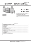
GASOLINE VEHICLES ONLY:
• TO AVOID UNINTENTIONALLY STARTING THE VEHICLE:
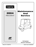
- DISCONNECT BATTERY CABLES, NEGATIVE (-) FIRST (FIGURE 1-1).
- DISCONNECT THE SPARK PLUG WIRE FROM THE SPARK PLUG.
• FRAME GROUND - DO NOT ALLOW TOOLS OR OTHER METAL OBJECTS TO CONTACT
FRAME WHEN DISCONNECTING BATTERY CABLES OR OTHER ELECTRIC WIRING. NEVER
ALLOW A POSITIVE WIRE TO TOUCH VEHICLE FRAME, ENGINE, OR METAL COMPONENT.
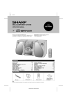
ELECTRIC VEHICLES ONLY:
• TO AVOID UNINTENTIONALLY STARTING THE VEHICLE, DISCONNECT BATTERIES AS SHOWN
(FIGURES 1-2 OR 1-3).
• ON POWERDRIVE PLUS VEHICLES, PLACE TOW SWITCH IN THE TOW POSITION BEFORE
DISCONNECTING BATTERIES.
• ON POWERDRIVE SYSTEM 48 VEHICLES, DISCHARGE THE CONTROLLER AS FOLLOWS
AFTER DISCONNECTING BATTERIES:
- TURN THE KEY SWITCH TO ON AND PLACE THE FORWARD/REVERSE HANDLE IN THE
REVERSE POSITION.
- SLOWLY DEPRESS THE ACCELERATOR PEDAL AND KEEP IT DEPRESSED UNTIL THE
REVERSE WARNING BUZZER CAN NO LONGER BE HEARD. WHEN THE BUZZER STOPS
SOUNDING, THE CONTROLLER IS DISCHARGED.
DS POWERDRIVE SYSTEM 48
AND POWERDRIVE PLUS
BATTERY DISCONNECT
AS SEEN FROM
PASSENGER SIDE
OF VEHICLE
FRONT
OF VEHICLE
FRO
OF VE NT
HICLE
3
4
5
REMOVE
NEGATIVE
CABLE FIRST
DISCONNECT BATTERY CABLES
BEFORE WORKING ON VEHICLE
2
1
6
REMOVE
NEGATIVE
CABLE FIRST
Figure 1-1 Gasoline Vehicle
DISCONNECT
BATTERY CABLES HERE
Figure 1-2 PowerDrive Vehicles
1
2
FRONT
OF VEHICLE
3
4
6
5
DISCONNECT
BATTERY CABLES HERE
Figure 1-3 V-Glide 36-Volt Vehicle
1998/1999 DS Golf Car Maintenance and Service Manual
Page 1-3
1
1
2
SECTION 2–VEHICLE SPECIFICATIONS
GENERAL INFORMATION
Club Car, Inc. reserves the right to change vehicle specifications and design of either gasoline or electric
vehicles at any time without obligation to make these changes on units previously sold.
DS
GASOLINE
SPECIFICATIONS
POWERDRIVE
SYSTEM 48
ELECTRIC
POWERDRIVE
PLUS
ELECTRIC
DS
36-VOLT
ELECTRIC
POWER SOURCE
Engine: 4 cycle, OHV, 286 cc, 9.0 hp rated., single cylinder, air cooled,
with pressure lubrication system.
•
Drive Motor: Direct drive, 48 volts DC, series wound, 3.1 hp.
•
Drive Motor: Direct drive, 48 volts DC, shunt wound, 3.2 hp.
•
Drive Motor: Direct drive, 36 volts DC, series wound, 2.97 hp.
•
Fuel System: Side draft carburetor with float bowl, fixed jets, fuel filter,
and impulse fuel pump.
•
Governor: Automatic ground speed sensing, internally geared in unitized
transaxle.
•
Ignition: Transistor electronic ignition with electronic RPM limiter.
•
Unitized Transaxle: Fully synchronized forward and reverse with neutral
and reduced speed reverse (11.8:1 forward, 17.1:1 reverse).
•
Transaxle: Double reduction helical gear with 12.28:1 direct drive axle.
Electrical System: Battery - 12 volt, 500 cold cranking amps at 0°, 650
cranking amps at 32°, 85 minute reserve and 35 amp charging capacity.
•
•
•
•
•
•
Electrical System: 48 volts DC, reduced speed reverse.
Electrical System: 36 volts DC, reduced speed reverse.
•
Batteries: High capacity, deep cycle, Trojan PowerDrive 8 volt, 117 min.
capacity.
•
•
•
•
Batteries: High capacity, deep cycle, Trojan 6 volt, 115 min. capacity.
•
Charger: Automatic, 17 amp PowerDrive; UL and CSA listed.
Charger: Automatic, 21 amp Accu-Power; UL and CSA listed.
•
Torque Converter: Automatic, variable speed, dry type.
•
STEERING/SUSPENSION/BRAKES
Steering: Self-adjusting rack and pinion.
•
•
•
•
Suspension: Front and rear tapered mono-leaf springs with dual hydraulic shocks.
•
•
•
•
Brakes: Dual rear wheel self-adjusting brakes with cast iron drums and
single brake pedal with automatic-release park brake.
•
•
•
•
Frame/Chassis: Twin I-Beam welded aluminum.
•
•
•
•
Front and Rear Body: Armorflex®
•
•
•
•
Body Finish: Matched paint finish over molded-in color.
•
•
•
•
Tires: 18.00 x 8.50 - 8.00 tubeless, 4 ply rated.
•
•
•
•
Standard Seating Capacity: 2 persons
•
•
•
•
Fairway Villager Seating Capacity: 4 persons
•
•
•
•
Fuel Tank: 7 gallons (26.5 liters), unleaded gasoline only.
•
BODY/CHASSIS
SEATING CAPACITY/FUEL CAPACITY
Specifications Continued on Next Page.
1998/1999 DS Golf Car Maintenance and Service Manual
Page 2-1
2
VEHICLE SPECIFICATIONS
General Information
DS
GASOLINE
POWERDRIVE
SYSTEM 48
ELECTRIC
POWERDRIVE
PLUS
ELECTRIC
DS
36-VOLT
ELECTRIC
Overall Length
91-1/2"
(232 cm)
91-1/2"
(232 cm)
91-1/2"
(232 cm)
91-1/2"
(232 cm)
Overall Width
47-1/4"
(120 cm)
47-1/4"
(120 cm)
47-1/4"
(120 cm)
47-1/4"
(120 cm)
Overall Height: At Steering Wheel.
48"
(122 cm)
48"
(122 cm)
48"
(122 cm)
48"
(122 cm)
Wheelbase
65-1/2"
(166 cm)
65-1/2"
(166 cm)
65-1/2"
(166 cm)
65-1/2"
(166 cm)
Ground Clearance
4-1/2"
(11 cm)
4-1/2"
(11 cm)
4-1/2"
(11 cm)
4-1/2"
(11 cm)
Front Wheel Tread
34-1/2"
(88 cm)
34-1/2"
(88 cm
34-1/2"
(88 cm
34-1/2"
(88 cm
Rear Wheel Tread
38-1/2"
(98 cm)
38-1/2"
(98 cm)
38-1/2"
(98 cm)
38-1/2"
(98 cm)
Weight: Standard electric vehicle (without batteries)
455 lbs.
(206 kg)
477 lbs.
(216 kg)
448 lbs.
(203 kg)
Weight: Fairway Villager electric vehicle (without batteries)
495 lbs.
(225 kg)
517 lbs.
(235 kg)
N/A
12 - 15 mph
(19 - 24 kph)
12 - 15 mph
(19 - 24 kph)
12 - 15 mph
(19 - 24 kph)
12 - 15 mph
(19 - 24 kph)
Clearance Circle (diameter)
17'-6"
(533 cm)
17'-6"
(533 cm)
17'-6"
(533 cm)
17'-6"
(533 cm)
Braking Distance: At 12 mph (19 kph)
14'
(427 cm)
14'
(427 cm)
14'
(427 cm)
14'
(427 cm)
SPECIFICATIONS
DIMENSIONS/WEIGHT
Weight: Standard gasoline powered vehicle (dry, without battery)
598 lbs.
(271 kg.)
Weight: Fairway Villager gasoline powered vehicle (dry)
638 lbs.
(289 kg.)
Forward Speed: At 2700 rpm
Page 2-2 1998/1999 DS Golf Car Maintenance and Service Manual
3
SECTION 3–GENERAL INFORMATION
There are four DS Golf Car models: the DS gasoline powered vehicle, the DS V-Glide 36-volt electric powered
vehicle, the DS PowerDrive System 48 (48-volt) electric vehicle, and the DS PowerDrive Plus (48-volt) electric
vehicle with motor braking. Throughout this manual, important features unique to each model are highlighted. We
urge the owner/operator to read and understand this manual, and to pay special attention to the features specific
to his/her vehicle(s).
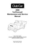
MODEL IDENTIFICATION
The serial number of the vehicle is printed on a bar code decal mounted on the frame directly above the
accelerator pedal (Example: A9801-123456 for Electric or AG9801-123456 for Gasoline). See Figure 3-1,
Page 3-1. There is also a second serial number decal mounted on the front body frame behind the center
dash panel. The center dash panel must be removed to access this decal (Figure 3-2, Page 3-1).
NOTE
• ALWAYS HAVE THE VEHICLE SERIAL NUMBER AT HAND WHEN ORDERING PARTS OR
MAKING INQUIRIES.
l
l
Help speed up play.
Dispose of litter properly.
Club Car, Inc.
SERIAL NUMBER DECAL
L NUMB
R
Club Car
204658
30917
P O BOX
STA GA
AUGU
SERIA
A9812-
ER
583947
SERIAL NUMBER
DECAL
SERIAL NUMBER
Club Car
R
P O BOX 204658
AUGUSTA GA 30917
A9801-123456
This vehicle is covered by one or more of the
following U.S. Patents as applicable: D271008
D292899, 4343503, 4539162, 4637270, 4821827
4826467, 5042519, 5083736 and other
patents pendings.
GO
Club
Figure 3-1 Serial Number Decal
REAR OF CENTER
DASH VIEWED FROM
THE FRONT OF
THE VEHICLE
(FRONT BODY
REMOVED)
Figure 3-2 Serial Number Decal Behind Dash
SAFETY COMMITTEE
If the golf car is to be rented or is part of a fleet, Club Car, Inc. recommends a safety committee be
appointed. One of the main concerns of this committee should be the safe operation of the golf cars.
This should include at a minimum:
• Where golf cars should be driven.
• Ensuring that proper warnings of driving hazards are displayed and visible.
NOTE
• SIGNS SUCH AS STEEP HILL AND SHARP TURN ARE AVAILABLE FROM THE GOLF CAR
MANUFACTURERS ASSOCIATION MEMBERS.
• Who should and who should not drive golf cars.
1998/1999 DS Golf Car Maintenance and Service Manual
Page 3-1
3
GENERAL INFORMATION
Pre-Operation Checklist
Safety Committee, Continued:
• Instructing first time drivers.
• Maintaining golf cars in a safe driving condition.
• How various rules are to be enforced.
The safety committee should include all these items and such others as the committee feels necessary or
appropriate.
PRE-OPERATION CHECKLIST
Each Club Car vehicle is thoroughly inspected and adjusted at the factory and by a Club Car distributor/dealer.
However, upon receipt of any new Club Car vehicle, become familiar with the controls and vehicle operation.
Carefully inspect each vehicle to be satisfied it is in proper working condition before accepting delivery.
Use the following checklist as a guide to inspect the new vehicle. This checklist may also be used in
conjunction with the Daily Pre-operation Safety Checklist (Periodic Maintenance, Section 10,
Maintenance and Service Supplement). Any problems should be corrected by a Club Car distributor/
dealer or a trained mechanic.
• General: All parts should be in place and properly installed. Be sure that all nuts, bolts, and screws are
tight. On the DS Gasoline vehicle, check all hose clamps for tight fit as well as starter belt for tightness.
• Warning Decals: Check to ensure that all warning and operation decals are in place. See the Vehicle
Identification Pages at the beginning of the Vehicle Owner’s Manual.
• Tires: Check for proper tire pressure. See Vehicle Capacities, Section 10, Maintenance and Service
Supplement.
• Batteries (electric vehicles): Check electrolyte to ensure that it is at its proper level. See Section 13,
Maintenance and Service Supplement. Check battery posts. Wires should be tight and free of corrosion. Charge batteries fully before first use of vehicle.
• Multi-Step Potentiometer (48 volt electric vehicles) and V-Glide Wiper Switch (36 volt electric
vehicles): Be sure accelerator switch cover is properly secured prior to operating the vehicle.
• Engine (gasoline vehicles): Check for proper engine oil level. See Engine Oil, Section 10, Maintenance and Service Supplement.
• Fuel (gasoline vehicles): Check fuel level. See Fueling Instructions, Section 10, Maintenance and
Service Supplement.
WARNING
• BE SURE THE PLASTIC HAS BEEN REMOVED FROM THE SEAT BOTTOM BEFORE
OPERATING THE VEHICLE. FAILURE TO DO SO MAY RESULT IN A FIRE, PROPERTY
DAMAGE, PERSONAL INJURY, OR DEATH.
PERFORMANCE INSPECTION
After becoming familiar with the vehicle’s controls and after reading and understanding the driving
instructions, take the vehicle for a test drive. Use the following checklist as a guide to inspect the new vehicle.
Any problems should be corrected by a CLUB CAR distributor/dealer or a trained technician.
All vehicles:
• Brakes: Be sure the brakes function properly. When brake pedal is fully depressed under moderate
pressure, it should not go more than halfway to the floor, and vehicle should come to a smooth, straight
stop within 14 feet. If the pedal goes more than halfway to the floor, or if the vehicle swerves or fails to
stop within 14 feet, have the brake system checked and adjusted as required. Brake adjustment must
be maintained so that the brake pedal cannot be depressed to the floor under any circumstances.
Page 3-2 1998/1999 DS Golf Car Maintenance and Service Manual
GENERAL INFORMATION
Controls
• Park Brake: When latched, the park brake should lock the wheels and hold the vehicle stationary (on
incline of 20% or less). It should release when either the accelerator or brake pedal is depressed.
• Reverse Buzzer: The reverse buzzer should sound as a warning when the vehicle is in REVERSE.
• Steering: The vehicle should be easy to steer and should not have any play in the steering wheel.
• Accelerator: With the key switch ON and the Forward/Reverse handle in the FORWARD position; as
the accelerator pedal is depressed, the engine or motor should start and the vehicle should come up
smoothly to full speed. When pedal is released it should return to the original position and the engine or
motor should stop. All DS (gasoline and electric) vehicles run at reduced speed in REVERSE.
• Governor (gasoline vehicles): Check maximum speed of the vehicle. The vehicle should run at 12-15
mph (19-24 kph) on a level surface.
• General: Listen for any unusual noises such as squeaks or rattles. Check the vehicle ride and performance. Have a CLUB CAR distributor/dealer or a trained mechanic investigate anything unusual.
DS PowerDrive Plus Vehicles with Motor Braking:
• Zero Speed Detect: With the vehicle parked on level ground and the park brake disengaged, place the
tow switch in the RUN position and attempt to push the vehicle. It should resist rolling (moving at no
more than 1 or 2 mph) with the Forward/Reverse handle in any position.
• “Pedal Up” Motor Braking: Accelerate the vehicle to full speed and then release the accelerator
pedal. Motor braking should quickly and smoothly slow the vehicle to approximately 9 mph. Motor braking will disengage when vehicle slows to 9 mph.
• “Pedal Down” Motor Braking: Accelerate down an incline with the accelerator pedal depressed.
When the vehicle reaches approximately 15 mph, motor braking should engage and moderate vehicle
speed between 15 and 16 mph, depending upon the grade of the hill.
CONTROLS
DANGER
• DO NOT OPERATE GASOLINE VEHICLE IN AN ENCLOSED AREA WITHOUT PROPER
VENTILATION. GASOLINE ENGINES PRODUCE CARBON MONOXIDE GAS, WHICH IS AN
ODORLESS, DEADLY POISON.
WARNING
• IF RENTING OR LOANING THE VEHICLE, MAKE SURE DRIVER IS FAMILIAR WITH ALL CONTROLS
AND OPERATING PROCEDURES BEFORE ALLOWING THE VEHICLE TO BE DRIVEN.
• DO NOT TAMPER WITH THE GASOLINE VEHICLE GOVERNOR. DOING SO WILL VOID THE
WARRANTY, AS WELL AS DAMAGE THE ENGINE AND OTHER COMPONENTS, AND COULD
RESULT IN PROPERTY DAMAGE, PERSONAL INJURY, OR DEATH DUE TO ACCIDENT AT
UNSAFE SPEED.
• DO NOT MODIFY OR CHANGE THE VEHICLE IN ANY WAY WHICH MIGHT AFFECT ITS
STABILITY OR HANDLING, OR INCREASE MAXIMUM SPEED BEYOND FACTORY
SPECIFICATIONS. PROPERTY DAMAGE, PERSONAL INJURY, OR DEATH COULD RESULT.
• DO NOT SHIFT THE FORWARD/REVERSE HANDLE WHILE THE VEHICLE IS MOVING. TO
AVOID INJURY TO AN UNSUSPECTING PASSENGER OR DAMAGE TO THE VEHICLE, ALWAYS
BRING THE VEHICLE TO A FULL STOP BEFORE SHIFTING THE SWITCH. A BUZZER WILL
SOUND AS A WARNING WHEN THE VEHICLE IS IN REVERSE.
• RELEASE THE ACCELERATOR PEDAL AND THEN DEPRESS THE BRAKE PEDAL FIRMLY
UNTIL THE VEHICLE STOPS. TO AVOID UNINTENTIONALLY STARTING OR ROLLING THE
VEHICLE, SET THE PARK BRAKE, TURN THE KEY SWITCH TO OFF, AND REMOVE THE KEY
WHEN LEAVING THE VEHICLE.
1998/1999 DS Golf Car Maintenance and Service Manual
Page 3-3
3
3
GENERAL INFORMATION
Controls
Controls, Continued:
KEY SWITCH
The key switch is mounted on the dash to the right of the steering column (Figure 3-3, Page 3-4). It has two
positions, OFF and ON, which are clearly labeled.
NOTE
• THE KEY CAN BE REMOVED WHEN THE KEY SWITCH IS IN THE OFF POSITION ONLY.
OFF
ON
Figure 3-3 Key Switch
Figure 3-4 Forward and Reverse Handle
FORWARD/REVERSE CONTROL
DS Gasoline, DS V-Glide Electric, and DS PowerDrive System 48
The Forward/Reverse shift handle is located on the seat support panel, below and to the right of the driver’s
right knee (Figure 3-4, Page 3-4). The handle has three distinct positions: F (forward), N (neutral), and R
(reverse). Rotate the handle towards the driver, F (forward), to run the vehicle in the FORWARD direction, or
towards the passenger, R (reverse), to run the vehicle in REVERSE. When the handle is in the straight up, or
N (neutral) position, the vehicle will not run. The engine on the DS gasoline vehicle will stop if it is shifted to
this position while running. DS electric and gasoline vehicles operate at reduced speed in REVERSE. When
the vehicle is in REVERSE, the reverse warning buzzer will sound.
DS PowerDrive Plus With Motor Braking
The Forward/Reverse rocker switch is located in the same place as the Forward/Reverse shift handle on all
other DS models; on the seat support panel below and to the right of the driver’s right knee. The Forward (F)
and Reverse (R) positions are clearly marked on the switch. Push down the F (forward) side of the switch to
run the vehicle in the FORWARD direction, or push down the R (reverse) side of the switch to run the vehicle
in REVERSE. When the switch is positioned with neither side down, the vehicle is in the NEUTRAL position
and the vehicle will not run if the accelerator pedal is depressed (Figure 3-5, Page 3-5).
NOTE
• THE REVERSE BUZZER WILL SOUND AS A WARNING WHEN THE VEHICLE IS IN REVERSE.
ACCELERATOR PEDAL
The accelerator pedal is the pedal on the right, with the word GO molded into it (Figure 3-6, Page 3-5).
Page 3-4 1998/1999 DS Golf Car Maintenance and Service Manual
GENERAL INFORMATION
Controls
NOTE
• THE OPERATION OF THE ACCELERATOR PEDAL DIFFERS FROM THAT OF AN
AUTOMOBILE. WHEN THE KEY SWITCH IS ON, AND THE SHIFT HANDLE IS IN EITHER
FORWARD OR REVERSE, DEPRESSING THE ACCELERATOR PEDAL WILL AUTOMATICALLY
RELEASE THE PARK BRAKE AND START THE VEHICLE MOVING IN THE DIRECTION
SELECTED (FORWARD OR REVERSE). AS THE ACCELERATOR PEDAL IS DEPRESSED,
SPEED WILL INCREASE UNTIL FULL SPEED IS REACHED. WHEN THE ACCELERATOR IS
RELEASED, POWER WILL BE CUT OFF AND THE ENGINE OR MOTOR WILL STOP RUNNING.
• POWERDRIVE PLUS VEHICLES ONLY: SEE “PEDAL-UP” AND “PEDAL-DOWN” MOTOR
BRAKING ON PAGE 3-3.
F
R
Figure 3-5 PowerDrive Plus Forward/Reverse Switch
Figure 3-6 Accelerator and Brake Pedals
BRAKE PEDAL
The brake pedal is the large pedal on the left with the word STOP molded into it (Figure 3-6, Page 3-5). To
slow or stop the vehicle, depress the brake pedal with your right foot (Figure 3-7, Page 3-6).
WARNING
• THE PARK BRAKE WILL RELEASE AUTOMATICALLY WHEN EITHER THE ACCELERATOR OR
BRAKE PEDAL IS DEPRESSED. THE PARK BRAKE HAS MULTIPLE LOCKING POSITIONS AND
SHOULD BE FIRMLY PRESSED AND LOCKED TO PREVENT THE VEHICLE FROM ROLLING.
PARK BRAKE PEDAL
The park brake pedal is the small raised portion in the upper left corner of the brake pedal. It has the word
PARK molded into it and the words PARK BRAKE marked on top of it (Figure 3-7, Page 3-6). To set the
park brake, depress the brake pedal firmly and tilt the park brake portion of the pedal forward with your foot
(Figure 3-8, Page 3-6).
GASOLINE VEHICLES ONLY
Neutral Lock-out
The vehicle has a neutral lock-out circuit that prevents the driver from starting the vehicle in NEUTRAL. If the
vehicle is started in FORWARD or REVERSE and then shifted to NEUTRAl, the engine will stop running. For
the convenience of the trained mechanic, there is a neutral lock-out cam located on the back of the Forward/
Reverse handle. If the neutral lock-out cam is pulled out approximately 3/8 in. (10 mm) and then rotated onehalf turn until it snaps into place, the cam will be in the SERVICE position (Figure 3-9, Page 3-7).
1998/1999 DS Golf Car Maintenance and Service Manual
Page 3-5
3
3
GENERAL INFORMATION
Controls
Neutral Lock-out, Continued:
This will allow the mechanic to run the engine in NEUTRAL for certain maintenance procedures. With the
cam in this position, the vehicle will not operate if Forward/Reverse handle is placed in either FORWARD or
REVERSE position. To put cam back into the OPERATE position, pull the cam out approximately 3/8 in. (10
mm) and rotate one-half turn until it snaps into place (Figure 3-10, Page 3-7). See following WARNING.
WARNING
• WITH THE CAM IN THE SERVICE POSITION AND THE ENGINE RUNNING, THE VEHICLE MAY
MOVE SUDDENLY IF THE FORWARD/REVERSE HANDLE IS SHIFTED OR ACCIDENTALLY
BUMPED. TO PREVENT THIS, CHOCK THE FRONT AND REAR WHEELS AND ALWAYS FIRMLY
SET THE PARK BRAKE BEFORE SERVICING OR LEAVING THE VEHICLE.
NOTE
• BE SURE TO RETURN THE CAM TO THE OPERATE POSITION AFTER SERVICING THE
VEHICLE, OR IT WILL NOT RUN WITH THE FORWARD/REVERSE HANDLE IN EITHER THE
FORWARD OR REVERSE POSITION.
Figure 3-7 Brake and Park Brake Pedals
Figure 3-8 Depress Park Brake Pedal
Choke
The choke is located on the seat support panel below and to the left of the driver’s left knee (Figure 3-11,
Page 3-7). If the vehicle is hard to start in cool or cold temperatures, simply push in the choke button with
your left hand. Hold it during start up and release the choke cover after the engine starts and runs smoothly.
Oil Light
The DS Gasoline golf car is equipped with a low oil warning light, located on the dash panel just above the
steering column (Figure 3-12, Page 3-7). If the oil warning light comes on, oil should be checked and added
to the engine as necessary before continuing to use the vehicle. The vehicle should never be driven with oil
warning light remaining on. If the oil warning light goes on and off, you may proceed, but oil should be added
at the first opportunity. If oil level is correct and the light stays on, have a trained mechanic check the vehicle.
CAUTION
• FAILURE TO ADD OIL IMMEDIATELY WHEN THE OIL WARNING LIGHT STAYS ON MAY
RESULT IN PERMANENT ENGINE DAMAGE.
Page 3-6 1998/1999 DS Golf Car Maintenance and Service Manual
GENERAL INFORMATION
Controls
POWERDRIVE SYSTEM 48 AND POWERDRIVE PLUS ELECTRIC VEHICLES ONLY
Battery Warning Light
PowerDrive System 48 and PowerDrive Plus vehicles feature a dash mounted warning light that, when vehicle
is in operation, indicates low battery voltage, or, when vehicle is being charged, indicates a charging problem
(Figure 3-12, Page 3-7). The battery warning light is controlled by the PowerDrive onboard computer.
NEUTRAL
NEUTRAL
FORWARD
Figure 3-9 Neutral Lock-out Cam - Service
FORWARD
Figure 3-10 Neutral Lock-out Cam - Operate
OIL LIGHT (Gasoline Vehicles)
BATTERY WARNING LIGHT
(48-Volt Vehicles)
+
CHOKE
Figure 3-11 Choke Button
Figure 3-12 Dash Warning Light
When the vehicle is in operation, the warning light will come on and remain illuminated if:
• Batteries’ voltage drops below 48 when there is no load on the batteries (the vehicle is stopped and
there are no accessories on).
• Batteries have discharged to less than 25% of their capacity.
If the warning light comes on during a round of golf, there is enough power remaining to finish the round, but
the car should be charged before being used again. If the warning light comes on and the vehicle is unable to
finish the round, have a Club Car distributor/dealer check the vehicle for a possible battery or electrical
system problem.
When the batteries receive an incomplete charge because 1) the DC power cord is disconnected, 2) AC
power to the charger is interrupted, 3) automatic charger shut-off occurs after 16 hours of operation, or 4) the
charger malfunctions, the warning light will indicate as follows:
• The warning light will not come on if the charge is 90% or more complete. The onboard computer will
retain in memory the amount of charge needed to fully replenish the batteries and will complete the
charge during the next charge cycle.
1998/1999 DS Golf Car Maintenance and Service Manual
Page 3-7
3
3
GENERAL INFORMATION
Controls
Battery Warning Light, Continued:
• When the charger is unplugged, the warning light will come on and remain illuminated for 10 seconds if
the charge is less than 90% complete but the car has enough power to complete 36 holes of golf. This
will alert the fleet operator that the car may be used, but that it must be charged to completion as soon
as possible.
• The warning light will repeatedly illuminate for 10 seconds, with 4 second intervals, if the charger times
out at 16 hours (see charger manual) and the batteries are not sufficiently charged. This indicates an
abnormal charge cycle. Charger and batteries should be checked by your Club Car distributor/dealer.
• The warning light will repeatedly illuminate for 10 seconds, with 4 second intervals, during a charge
cycle (DC plug is still connected) if AC power to the charger is interrupted. The light will go out when AC
power is restored.
POWERDRIVE PLUS ELECTRIC VEHICLES ONLY
Tow/Run Switch
WARNING
• TO AVOID POSSIBLE BATTERY EXPLOSION, THE TOW/RUN SWITCH MUST BE IN THE TOW
POSITION BEFORE DISCONNECTING OR CONNECTING BATTERY WIRES.
• WHEN THE TOW/RUN SWITCH IS IN THE TOW POSITION, ALL MOTOR BRAKING FUNCTIONS,
INCLUDING ZERO-SPEED DETECT, ARE DISABLED.
VENT
SHUT-OFF
VALVE
ING
ARN
TOW
RUN
W
TO CARBURETOR
F
VENT TUBES
Figure 3-13 Tow/Run Switch
Figure 3-14 Fuel Tank, Vent, and Lines
All 1998/1999 DS PowerDrive Plus vehicles (with motor braking) are equipped with a Tow/Run switch,
located under the seat just above the Forward/Reverse rocker switch (Figure 3-13, Page 3-8). The Tow/Run
switch must be in the RUN position in order to operate the vehicle. When the switch is in the TOW position,
power to the vehicle electrical components is turned off and the vehicle will not operate.
NOTE
• AFTER PLACING THE SWITCH IN TOW POSITION, ALLOW 10 SECONDS BEFORE SWITCHING
BACK TO RUN.
• AFTER PLACING THE SWITCH IN THE RUN POSITION, ALLOW 10 SECONDS BEFORE
OPERATING THE VEHICLE.
Page 3-8 1998/1999 DS Golf Car Maintenance and Service Manual
GENERAL INFORMATION
Driving Instructions
The Tow/Run switch should be placed in the TOW position under the following conditions:
• Before Towing the Vehicle: Place the Tow/Run switch in the TOW position to disable all motor braking
functions, thus preventing possible damage that could occur to the vehicle or electrical components if
the vehicle is towed while the Zero-Speed Detect motor braking function is operating.
• Before Disconnecting or Attaching Battery Wires: Place the Tow/Run switch in the TOW position to
turn off power to the vehicle electrical system, thus preventing severe arcing and possible battery
explosion as the battery wires are disconnected.
• For Long Term Storage: Place the Tow/Run switch in the TOW position to turn off power to the vehicle
electrical system, preventing vehicle electrical components from discharging the batteries.
DRIVING INSTRUCTIONS
WARNING
• IF RENTING OR LOANING VEHICLE, MAKE SURE DRIVER IS FAMILIAR WITH ALL CONTROLS
AND OPERATING PROCEDURES BEFORE ALLOWING THE VEHICLE TO BE DRIVEN.
• NO MORE THAN TWO PEOPLE SHOULD BE ON THE VEHICLE AT ONE TIME.
• THE VEHICLE IS NOT SPECIALLY EQUIPPED FOR HANDICAPPED PERSONS. BE SURE ALL
PERSONS CAN PROPERLY OPERATE THE VEHICLE PRIOR TO ALLOWING THEM TO DRIVE
THE VEHICLE.
• FOR NIGHT USE, THE VEHICLE MUST BE EQUIPPED WITH HEADLIGHTS, TAILLIGHTS, AND
REFLECTORS.
• STOP THE VEHICLE BEFORE SHIFTING THE FORWARD/REVERSE HANDLE. FAILURE TO DO
SO MAY RESULT IN INJURY TO AN UNSUSPECTING PASSENGER AND (OR) DAMAGE TO THE
VEHICLE. A BUZZER WILL SOUND AS A WARNING WHEN THE VEHICLE IS IN REVERSE.
WHEN DRIVING THE VEHICLE:
• OPERATE THE VEHICLE FROM THE DRIVER’S SEAT ONLY.
• TO PREVENT FALLS FROM THE VEHICLE, REMAIN SEATED IN A MOVING VEHICLE AND HOLD
ON TO SEAT HANDLES OR HANDRAILS AT ALL TIMES. DRIVER SHOULD KEEP BOTH HANDS
ON THE STEERING WHEEL WHEN THE VEHICLE IS IN MOTION.
• TO PREVENT THE POSSIBILITY OF SERIOUS INJURY, KEEP ENTIRE BODY INSIDE THE
VEHICLE.
• TO PREVENT OVERTURNING THE VEHICLE, DRIVE SLOWLY IN TURNS.
• TO PREVENT OVERTURNING THE VEHICLE, DRIVE SLOWLY STRAIGHT UP AND DOWN
SLOPES. DO NOT DRIVE THE VEHICLE ON SLOPES EXCEEDING 20% INCLINE.
• TO AVOID POSSIBLE INJURY TO AN UNSUSPECTING PASSENGER AND (OR) DAMAGE TO THE
VEHICLE, AVOID SUDDEN STARTS, SUDDEN STOPS, AND ABRUPT TURNS.
• TO AVOID THE POSSIBILITY OF LOSING CONTROL OF OR OVERTURNING VEHICLE, REDUCE
SPEED FOR ADVERSE DRIVING CONDITIONS SUCH AS WET GRASS OR ROUGH TERRAIN.
• DO NOT USE THE VEHICLE ON PUBLIC ROADS. IT IS NOT DESIGNED OR INTENDED FOR
STREET USE AND SHOULD NOT BE LICENSED FOR USE ON PUBLIC ROADS.
• OBEY ALL LOCAL RULES CONCERNING GOLF CARS.
• THE VEHICLE SHOULD BE DRIVEN IN ONLY SPECIFIED AREAS BY TRAINED DRIVERS.
• TO AVOID BEING STRUCK, DO NOT STAND IN FRONT OF OR BEHIND THE VEHICLE.
• DO NOT DRIVE WHILE UNDER THE INFLUENCE OF ALCOHOL, DRUGS, OR MEDICATIONS.
1998/1999 DS Golf Car Maintenance and Service Manual
Page 3-9
3
3
GENERAL INFORMATION
Driving Instructions
Driving Instructions, Continued:
No one should drive the vehicle without first being instructed in the proper operation and use of the vehicle
controls. An experienced operator should accompany each first-time driver on a test drive before allowing
him(her) to operate the vehicle alone. Only licensed drivers should be allowed to drive this vehicle.
To ensure safe operation of the vehicle, follow exactly and in order, all of the following procedures. Read and
understand all instructions prior to driving the vehicle.
STARTING THE VEHICLE
1.
2.
3.
4.
Read safety warnings located on dash and (or) above pedals.
Turn key to the ON position and be sure nothing is in your path.
Select direction by placing shifter in desired position (F = forward or R = reverse).
Depress accelerator pedal. The park brake will release automatically and the vehicle will start to move.
As the accelerator pedal is depressed, speed will increase until full speed is reached.
WARNING
• VEHICLE OPERATOR MUST CONTROL SPEED WHEN GOING DOWNHILL.
GASOLINE VEHICLE ONLY:
• NEVER SHIFT THE VEHICLE OUT OF FORWARD WHILE GOING DOWNHILL. IF YOU DO, YOU
WILL NOT BE ABLE TO SHIFT INTO REVERSE OR BACK INTO FORWARD UNTIL STOPPED.
• DEPRESS THE BRAKE PEDAL AS NECESSARY AND PARTIALLY DEPRESS THE
ACCELERATOR WHEN DESCENDING A HILL. WITH THE ACCELERATOR PEDAL PARTIALLY
DEPRESSED, THE GOVERNOR WILL CAUSE THE ENGINE TO ASSIST THE BRAKES IN
CONTROLLING DOWNHILL SPEED.
POWERDRIVE PLUS VEHICLE (WITH MOTOR BRAKING) ONLY:
• “PEDAL DOWN” OR “PEDAL UP” MOTOR BRAKING MAY BE USED TO CONTROL SPEED WHEN
GOING DOWNHILL (SEE PERFORMANCE INSPECTION, PAGE 3-2). HOWEVER, TERRAIN OR
OTHER CONDITIONS MAY REQUIRE THAT PEDAL BRAKING BE USED IN CONJUNCTION
WITH MOTOR BRAKING.
STOPPING THE VEHICLE
WARNING
• DRIVING THROUGH WATER MAY AFFECT THE BRAKES. AFTER DRIVING THROUGH WATER,
CHECK EFFECTIVENESS OF THE BRAKES BY GENTLY DEPRESSING THE BRAKE PEDAL. IF
THE VEHICLE DOES NOT SLOW DOWN AT THE NORMAL RATE, CONTINUE TO DEPRESS THE
BRAKE PEDAL UNTIL THE BRAKES DRY OUT AND NORMAL PERFORMANCE RETURNS.
CAUTION
• WHEN STOPPED ON A HILL, USE THE BRAKE PEDAL TO HOLD YOUR POSITION. DO NOT
USE THE ACCELERATOR PEDAL.
To stop the vehicle, release the accelerator pedal and depress the brake pedal until the vehicle comes to a
complete stop.
PARKING AND LEAVING THE VEHICLE
1. After stopping vehicle, firmly depress park brake pedal until it locks. This will prevent vehicle from rolling.
2. Turn the key switch to OFF and place the shift handle in the NEUTRAL position. Remove the key when
the vehicle is not in use.
Page 3-10 1998/1999 DS Golf Car Maintenance and Service Manual
GENERAL INFORMATION
Towing
• PowerDrive Plus Vehicles (Motor Braking) Only: When the vehicle Tow/Run switch is in the RUN
position, (with the Forward/Reverse handle or key switch in any position), the “zero speed detect” function will prevent the vehicle from rolling at more than 1 or 2 mph unless the accelerator is depressed.
This prevents the possibility of a parked vehicle (with the park brake disengaged) rolling away too fast
to be overtaken on foot. See “Zero Speed Detect” on Page 3-3.
TOWING
WARNING
• NEVER TOW THE VEHICLE ON PUBLIC STREETS OR HIGHWAYS.
• USE ONLY APPROVED CLUB CAR TOW BARS.
• TURN THE KEY SWITCH TO OFF AND PLACE THE FORWARD/REVERSE HANDLE IN NEUTRAL
BEFORE TOWING THE VEHICLE.
• EXTREME CAUTION SHOULD BE USED WHEN TOWING ANY VEHICLE.
• DO NOT EXCEED 5 MPH (8 KPH) TOWING SPEED.
• DO NOT ALLOW PASSENGERS IN THE VEHICLES BEING TOWED.
• AVOID SUDDEN STARTS, SUDDEN STOPS, AND TIGHT TURNS WHEN TOWING.
• DO NOT TOW MORE THAN ONE CLUB CAR VEHICLE WITH ANOTHER CLUB CAR VEHICLE. IF
MORE THAN ONE VEHICLE MUST BE TOWED, USE AN ADEQUATELY POWERED VEHICLE
(TRACTOR OR FULL SIZED TRUCK) PROPERLY FITTED, WITH A TOW HITCH HEIGHT OF 11
INCHES. ONLY HEAVY-DUTY TOW BARS SHOULD BE USED FOR MULTI-VEHICLE TOWING.
NEVER TOW MORE THAN FIVE VEHICLES AT ONE TIME.
• POWERDRIVE PLUS VEHICLE (WITH MOTOR BRAKING) ONLY: PLACE THE TOW/RUN
SWITCH IN THE TOW POSITION. THE VEHICLE WILL NOT ROLL OTHERWISE.
All vehicles are equipped with both front and rear tow bar attaching points. A light duty tow bar is available for
break-down towing and single vehicle towing. A heavy duty detachable tow bar and a heavy duty onboard
tow bar are available for multi-vehicle towing. Observe all of the above warning statements when towing.
TRANSPORTING ON A TRAILER
If the vehicle must be transported over long distances or on public highways, it should be done on an
approved trailer. See following WARNIING:
WARNING
• FOR USE ON PUBLIC ROADS, THE TRAILER MUST MEET ALL FEDERAL, STATE, AND LOCAL
REQUIREMENTS SUCH AS TAILLIGHTS, BRAKE LIGHTS, ETC.
• NEVER TOW A CLUB CAR VEHICLE BEHIND A PASSENGER VEHICLE OR TRUCK ON A
PUBLIC ROAD UNLESS IT IS ON AN APPROVED TRAILER.
• ALWAYS USE AN APPROVED TRAILER THAT HAS A LOAD RATING OF 1200 LB (544 KG) PER
VEHICLE TO BE TOWED (EXAMPLE: A TWO-CAR TRAILER SHOULD BE RATED AT 2 X 1200 =
2400 LB (2 X 544 = 1088 KG)).
• THE VEHICLE TO BE TOWED SHOULD BE TIED SECURELY TO THE TRAILER, WITH THE
FORWARD/REVERSE HANDLE IN NEUTRAL, THE KEY SWITCH OFF, AND THE PARK BRAKE
FIRMLY DEPRESSED AND LOCKED.
• WHEN TOWING ON A TRAILER, REDUCE NORMAL ROAD SPEED OF THE TOW VEHICLE.
• BECAUSE OF ADDED LENGTH OF THE TRAILER, USE CAUTION WHEN TURNING A CORNER.
• REMOVE THE VEHICLE WINDSHIELD BEFORE TRANSPORTING ON A TRAILER.
• GASOLINE VEHICLE ONLY: TURN FUEL SHUT-OFF VALVE TO OFF (FIGURE 3-14, PAGE 3-8).
1998/1999 DS Golf Car Maintenance and Service Manual
Page 3-11
3
3
GENERAL INFORMATION
Storage - Gasoline Vehicle
STORAGE - GASOLINE VEHICLE
To prepare your vehicle for extended off season storage:
1. Store vehicle in a cool place. This will prevent self-discharge of the battery. If the battery appears to be
weak, have it charged using an automotive-type 12-volt battery charger rated 10 amps or less.
DANGER
• GASOLINE—FLAMMABLE! EXPLOSIVE! DO NOT SMOKE. KEEP SPARKS AND FLAMES
AWAY FROM THE AREA OF THE VEHICLE.
• NEVER ATTEMPT TO DRAIN GASOLINE WHEN THE ENGINE IS HOT OR WHILE IT IS
RUNNING. BE SURE TO CLEAN UP ANY SPILLED GASOLINE BEFORE OPERATING VEHICLE.
• STORE GASOLINE IN AN APPROVED GASOLINE CONTAINER ONLY. STORE IN A WELLVENTILATED AREA AWAY FROM SPARKS, OPEN FLAMES, HEATERS, OR HEAT SOURCES.
• DO NOT SERVICE, REPAIR, OR OPERATE IN AN ENCLOSED AREA WITHOUT PROPER
VENTILATION. THE ENGINE PRODUCES CARBON MONOXIDE WHICH IS AN ODORLESS,
DEADLY POISON.
• KEEP GASOLINE OUT OF THE REACH OF CHILDREN.
• DO NOT SIPHON GASOLINE FROM THE VEHICLE.
WARNING
• DO NOT ATTEMPT TO CHARGE A BATTERY IF IT IS FROZEN OR IF THE CASE IS BULGED.
DISCARD THE BATTERY. FROZEN BATTERIES CAN EXPLODE.
CAUTION
• BATTERIES IN A LOW STATE OF CHARGE WILL FREEZE AT LOW TEMPERATURES.
2. Drain carburetor.
2.1. Place the Forward/Reverse handle in the NEUTRAL position and the neutral lock-out cam in the
SERVICE position. Turn the fuel shut-off valve to the CLOSED (OFF) position and run the engine
until fuel remaining in the carburetor and fuel lines is used up and the engine stalls. Return the
neutral lock-out cam to OPERATE position.
2.2. Loosen (do not remove) carburetor drain screw and drain fuel remaining in bowl into a small container, then pour fuel from the container into vehicle fuel tank. Retighten carburetor drain screw.
2.3. Disconnect fuel vent line from fuel tank vent nipple.
2.4. Plug the fuel tank vent nipple so that it is air tight. We recommend using a slip-on vinyl cap.
3. To protect the engine, remove the spark plug and pour 1/2 ounce of SAE 10 weight oil into the engine
through the spark plug hole. Rotate the engine crankshaft several times and then re-install spark plug.
WARNING
• TURN THE KEY SWITCH OFF, REMOVE THE KEY, AND LEAVE THE FORWARD/REVERSE
HANDLE IN THE NEUTRAL POSITION DURING STORAGE. THIS IS TO PREVENT
UNINTENTIONALLY STARTING THE VEHICLE.
4. Increase tire pressure to 20 psi (.96 kPa).
Page 3-12 1998/1999 DS Golf Car Maintenance and Service Manual
GENERAL INFORMATION
Storage - Electric Vehicle
5. Grease front suspension and do all quarterly periodic lubrication. See Periodic Lubrication Schedule, Section 10, Maintenance and Service Supplement.
6. Thoroughly clean front body, rear body, seats, engine compartment, and underside of vehicle.
7. Do not latch the park brake. Chock wheels to prevent the vehicle from rolling.
TO RETURN THE STORED VEHICLE TO SERVICE
1. Restore fuel system to operation.
1.1. Remove plug from the fuel tank vent nipple and connect the vent line to the nipple. Open fuel
shut-off valve.
1.2. Place the Forward/Reverse handle in the NEUTRAL position and the neutral lock-out cam in the
SERVICE position. Crank the engine until fuel is pumped into the carburetor and fuel lines and
the engine starts. Turn engine off and return neutral lock-out cam to the OPERATE position.
2. Readjust tire pressure to 12-14 psi (.57/.67 kPa).
3. Perform the Pre-Operation Checklist (see pages 3-2 and 3-3).
NOTE
• DUE TO THE OIL ADDED TO THE ENGINE IN PREPARATION FOR STORAGE, THE ENGINE
MAY SMOKE EXCESSIVELY FOR A SHORT WHILE WHEN RUNNING IT FOR THE FIRST TIME
AFTER STORAGE.
STORAGE - ELECTRIC VEHICLE
WARNING
• TURN THE KEY SWITCH OFF, REMOVE THE KEY, AND LEAVE THE FORWARD/REVERSE
HANDLE IN THE NEUTRAL POSITION DURING STORAGE. THIS IS TO PREVENT
UNINTENTIONALLY STARTING THE VEHICLE.
• POWERDRIVE PLUS VEHICLES (WITH MOTOR BRAKING) ONLY: PLACE THE TOW/RUN
SWITCH IN THE TOW POSITION.
• DO NOT ATTEMPT TO CHARGE FROZEN BATTERIES OR BATTERIES WITH BULGED CASES.
DISCARD THE BATTERY. FROZEN BATTERIES CAN EXPLODE.
CAUTION
• BATTERIES IN LOW STATE OF CHARGE WILL FREEZE AT LOW TEMPERATURES.
• WHEN WASHING THE VEHICLE, DO NOT DIRECT WATER STREAM AT THE MULTI-STEP
POTENTIOMETER (48-VOLT VEHICLES) OR V-GLIDE SPEED SWITCH (36-VOLT VEHICLE),
FORWARD AND REVERSE SWITCH, OR OTHER ELECTRICAL COMPONENT.
• IF BATTERY WIRE TERMINALS ARE DAMAGED OR CORRODED, THEY SHOULD BE
REPLACED OR CLEANED AS NECESSARY. FAILURE TO DO SO MAY CAUSE THEM TO
OVERHEAT DURING OPERATION.
1. Fully charge batteries. See Batteries, Section 13, Maintenance and Service Supplement.
2. Wash off any corrosion around the terminals with a solution of baking soda and water (one cup per gallon of water), then rinse solution from the batteries (do not allow this solution to enter the batteries). Let
the terminals dry and coat them with Battery Terminal Spray, Club Car Part No. 1014305.
3. Store in a cool, dry place. This will prevent self-discharge of the batteries.
1998/1999 DS Golf Car Maintenance and Service Manual
Page 3-13
3
3
GENERAL INFORMATION
Storage - Electric Vehicle
Storage - Electric Vehicle, Continued:
4. Adjust tire pressure to 20 psi (.96 kPa).
5. Grease front suspension and do all quarterly periodic lubrication. See Periodic Lubrication Schedule, Section 10, Maintenance and Service Supplement.
6. Thoroughly clean front body, rear body, seats, battery compartment, and underside of vehicle.
7. Do not latch the park brake. Chock wheels to prevent the vehicle from rolling.
8. Keep batteries fully charged during storage. See Batteries, Section 13, Maintenance and Service
Supplement.
• Charge 36-volt vehicles with Accu-Power battery chargers every 6-8 weeks as necessary. If it is not
possible or practical to charge the batteries, leave them disconnected while the vehicle is in storage.
• Leave PowerDrive System 48 and PowerDrive Plus vehicles with PowerDrive chargers plugged in during storage. The PowerDrive storage charge feature will automatically charge the batteries as needed
throughout storage period. If it is not possible to charge the batteries, leave the batteries disconnected
during storage. See Batteries, Section 13, Maintenance and Service Supplement.
NOTE
• A POWERDRIVE SYSTEM 48 OR POWERDRIVE PLUS VEHICLE WILL NOT OPERATE WHILE
PLUGGED TO A CHARGER.
TO RETURN THE STORED VEHICLE TO SERVICE
1. Fully charge batteries. See Batteries, Section 13, Maintenance and Service Supplement.
2. Readjust tire pressure to 18-20 psi (.86/.96 kPa).
3. Perform the Pre-Operation Checklist. See pages 3-2 and 3-3.
Page 3-14 1998/1999 DS Golf Car Maintenance and Service Manual
4
SECTION 4–BODY AND TRIM
WARNING
• ONLY TRAINED MECHANICS SHOULD REPAIR OR SERVICE THIS VEHICLE. ANYONE DOING
EVEN SIMPLE REPAIRS OR SERVICE SHOULD HAVE KNOWLEDGE AND EXPERIENCE IN
GENERAL ELECTRICAL AND MECHANICAL REPAIR. FOLLOW ALL PROCEDURES EXACTLY.
• HEED DANGER, WARNING, AND CAUTION STATEMENTS IN THIS MANUAL, AS WELL AS
MANUFACTURERS’ WARNINGS ON BODY REPAIR AND CLEANING PRODUCTS.
• ALWAYS WEAR SAFETY GLASSES OR APPROVED EYE PROTECTION WHILE SERVICING THE
VEHICLE. WEAR A FULL FACE SHIELD WHEN WORKING WITH BATTERIES.
• ALWAYS WEAR A RESPIRATOR APPROVED FOR DUST AND MIST WHEN CUTTING, SANDING,
PAINTING, OR REPAIRING BODY PANELS.
• DO NOT SWALLOW OR INHALE CLEANING PRODUCTS. USE IN A WELL-VENTILATED AREA.
• ALWAYS WEAR PROTECTIVE GLOVES. CLEANING PRODUCTS MAY BE HARMFUL OR
IRRITATING TO SKIN.
• TURN KEY SWITCH OFF, PLACE FORWARD/REVERSE HANDLE IN THE NEUTRAL POSITION,
AND REMOVE KEY BEFORE SERVICING THE VEHICLE.
• DO NOT WEAR LOOSE CLOTHING. REMOVE JEWELRY SUCH AS RINGS, WATCHES, CHAINS,
ETC. WHEN SERVICING VEHICLE.
• USE INSULATED TOOLS WHEN WORKING NEAR BATTERIES OR ELECTRICAL CONNECTIONS.
• MOVING PARTS! - DO NOT ATTEMPT TO SERVICE VEHICLE WITH ENGINE/MOTOR RUNNING.
• HOT! - DO NOT ATTEMPT TO SERVICE VEHICLE WITH HOT MOTOR, RESISTORS, ENGINE,
OR EXHAUST SYSTEM. FAILURE TO HEED THIS WARNING COULD RESULT IN SEVERE
BURNS.
GASOLINE VEHICLE:
• TO AVOID UNINTENTIONALLY STARTING THE VEHICLE:
- DISCONNECT THE BATTERY CABLES, NEGATIVE (-) FIRST (SEE SECTION 1, FIGURE 1-1).
- DISCONNECT THE SPARK PLUG WIRE FROM THE PLUG.
• FRAME GROUND - DO NOT ALLOW TOOLS OR OTHER METAL OBJECTS TO CONTACT
FRAME WHEN DISCONNECTING BATTERY CABLES OR OTHER ELECTRIC WIRING. NEVER
ALLOW A POSITIVE WIRE TO TOUCH THE VEHICLE FRAME, ENGINE, OR OTHER METAL
COMPONENT.
ELECTRIC VEHICLE:
• TO AVOID UNINTENTIONALLY STARTING THE VEHICLE, DISCONNECT BATTERIES AS SHOWN
(SECTION 1, FIGURE 1-2 OR 1-3).
• ON POWERDRIVE PLUS VEHICLES, PLACE TOW SWITCH IN THE TOW POSITION BEFORE
DISCONNECTING BATTERIES.
• DISCHARGE THE CONTROLLER AS FOLLOWS AFTER DISCONNECTING BATTERIES:
- TURN THE KEY SWITCH TO ON AND PLACE THE FORWARD/REVERSE HANDLE IN THE
REVERSE POSITION.
- SLOWLY DEPRESS THE ACCELERATOR PEDAL AND KEEP IT DEPRESSED UNTIL THE
REVERSE WARNING BUZZER CAN NO LONGER BE HEARD. WHEN THE BUZZER STOPS
SOUNDING, THE CONTROLLER IS DISCHARGED.
1998/1999 DS Golf Car Maintenance and Service Manual
Page 4-1
4
BODY AND TRIM
General Information
CAUTION
• DO NOT USE DETERGENTS OR CLEANING SOLVENTS THAT CONTAIN AMMONIA, AROMATIC
SOLVENTS, OR ALKALI MATERIALS ON BODY PANELS OR SEATS.
• DO NOT ALLOW BATTERY ACID TO DRIP ON BODY PANELS. BATTERY ACID WILL CAUSE
PERMANENT BLEMISHES. WASH ACID OFF BODY PANELS IMMEDIATELY.
• DO NOT ALLOW CLEANING PRODUCTS TO CONTACT CLOTHES OR VEHICLE SURFACES
OTHER THAN THOSE FOR WHICH CLEANING PRODUCTS ARE INTENDED.
• THE INFORMATION IN THIS SECTION APPLIES TO ONLY THOSE 1999 VEHICLES WITH THE
MATCHED PAINT OVER PRIMER MONOCOAT FINISH. SEE NOTE BELOW.
NOTE
• THE MONOCOAT FINISH WAS INCORPORATED ON A DIFFERENT DATE FOR EACH COLOR.
THE DATE A VEHICLE BODY WAS PAINTED IS PRINTED ON A SMALL WHITE OR ORANGE
STICKER AFFIXED TO THE UNDERSIDE OF THE FRONT BODY AND ON THE SIDE PANEL
INSIDE THE ENGINE COMPARTMENT ON THE REAR BODY (IT MAY BE NECESSARY TO
REMOVE THE BODY TO SEE THE STICKER). A WHITE STICKER TYPICALLY WILL SHOW THE
MONTH/DAY/YEAR THE BODY PART WAS PAINTED, WHEREAS AN ORANGE STICKER WILL
SHOW ONLY THE MONTH/DAY AND THE NUMBER 2 OR 3 (WORK SHIFT). IF A STICKER
SHOWS A DATE EARLIER THAN THAT LISTED BELOW FOR A PARTICULAR COLOR, USE THE
REPAIR PROCEDURES IN THE 1995-1996 DS MAINTENANCE AND SERVICE MANUAL
(PUBLICATION PART NUMBER 1019051-01).
MONOCOAT PAINT INCORPORATION DATES
Color
Date
Serial No. (Electric)
Serial No. (Gasoline)
Beige
07/7/97
A9748-625345
AG9748-625464
White
09/02/97
A9805-644884
AG9804-643471
Gray
12/01/97
A9818-659791
AG9819-659936
Dark Blue
12/01/97
A9818-659791
AG9819-659936
Red
01/12/98
A9823-665486
AG9823-664981
Dark Green
08/18/97
A9804-642618
AG9804-642551
Black
07/28/97
A9752-628473
AG9752-628336
Classic Blue
03/30/98
A9835-690194
AG9835-688201
Burgundy
03/30/98
A9835-690194
AG9835-688201
GENERAL INFORMATION
Each vehicle is equipped with an injection molded Armorflex® front and rear body. Use a mild soap or detergent with a sponge or soft cloth for normal cleaning. Battery acid, fertilizers, tars, asphalt, creosote, paint, or
chewing gum should be removed immediately to prevent possible stains. Because the finish on the vehicle is
the same as the finish on today’s automobiles, commercial automotive cleaning products should be used.
FRONT AND REAR BODY REPAIR
STRESS LINES OR STREAKS
Repeated flexing of the body can cause white stress lines or streaks to appear. To remove them:
Page 4-2 1998/1999 DS Golf Car Maintenance and Service Manual
BODY AND TRIM
Front and Rear Body Repair
1. Hold a heat gun 12 in. (30 cm) away from the affected area, with the gun on its lowest heat setting.
2. Slowly wave the heat gun back and forth over the affected area until the streak fades.
3. It may be necessary to move the gun closer to the body to fade the streak, but under no circumstances
should the gun be held closer than 6 in. (15 cm) to the body.
CAUTION
• HOLDING THE HEAT GUN TOO CLOSE TO THE BODY COULD MELT THE BODY OR DAMAGE
THE FINISH SURFACE.
DEFORMATION
Deformations in the body can be repaired using a procedure similar to the one used to remove stress lines.
To remove deformations:
1. Hold a heat gun 12 in. (30 cm) away from the affected area, with the gun on its lowest heat setting.
2. Periodically remove the heat gun and bend the body in the opposite direction of the deformation.
3. Continue heating and bending the body until the original shape returns. Under no circumstances
should the gun be held closer than 6 in. (15 cm) to the body.
MINOR SCRATCHES AND SURFACE BLEMISHES
1. Thoroughly clean the affected area using strong, non-abrasive detergent and hot water, then clean with
Ultra-Kleen® Solvent Cleaner to remove any oil based contaminants.
2. Lightly buff imperfection with a clean, soft cloth or buff pad. Do not use any kind of polishing compound.
3. Wax the entire body part to restore luster and weather protection.
SMALL SCRATCHES THAT CANNOT BE BUFFED OUT
1. Thoroughly clean the affected area with alcohol and then dry thoroughly.
2. Using 240 grit or finer sandpaper, lightly sand the scratch to feather the edges. Finish sand the scratch
with 320 grit or finer paper to remove gloss from the surface. Sand as little body surface as possible
beyond the scratch.
CAUTION
• BE CAREFUL NOT TO SAND COMPLETELY THROUGH FINISH TO THE BODY MATERIAL. IF
THE FINISH IS SANDED THROUGH AND THE TPO BODY MATERIAL EXPOSED, PROCEED TO
STEP 6.
3. Using the brush in the bottle cap of the touch-up paint (available from Club Car Service Parts, see color
chart at top of page 4-4), apply paint to the scratch. Multiple layers of paint may be required to fill the
scratch.
4. Allow paint to dry completely, then lightly buff the imperfection.
5. Wax the entire body part to restore luster and weather protection.
6. If the TPO body material is exposed, apply a light coat of adhesion promoter (Club Car Part No.
101978901) to only the bare body material.
7. Fill the scratch with body filler (Club Car Part No. 1017295). Allow the filler to dry and then sand lightly.
8. Apply primer to the filled and promoter covered area. Allow the primer to dry, then perform steps 3
through 5 above.
1998/1999 DS Golf Car Maintenance and Service Manual
Page 4-3
4
4
BODY AND TRIM
Seat
Front and Rear Body Repair, Continued:
Club Car Touch-Up Paint Part Numbers
Beige
1019972-01
White
1019972-02
Gray
1019972-04
Red
1019972-06
Dark Blue
1019972-08
Dark Green
1019972-09
Black
1019972-10
Classic Blue
1019972-11
Burgundy
1019972-12
GOUGES, PUNCTURES, TEARS, LARGE SCRATCHES, AND ABRASIONS
Touch up is not recommended. Replace the entire body part or have it repaired by a professional paint and
body repair shop with experience repairing TPO bodies.
SEAT
Proper cleaning of the seat will make it last longer. Use the following guidelines:
Light Soiling: A solution of 10% liquid dish soap and warm water applied with a soft, damp cloth is
recommended. For imbedded dirt, a soft bristle brush may be used. Wipe away residue with a water
dampened cloth.
Heavy Soiling: Dampen a soft, white cloth with lighter fluid (naptha) and rub gently. Then rinse with a
water dampened cloth. See following DANGER.
DANGER
• FLAMMABLE! EXPLOSIVE! DO NOT SMOKE. KEEP SPARKS AND FLAMES AWAY FROM SEAT
AREA WHILE CLEANING. USE IN A WELL-VENTILATED AREA.
For Difficult Stains:
- Dampen a soft, white cloth with a solution of 10% household bleach (sodium hypochlorite) and 90% water.
Rub gently to remove stain, then rinse with a water dampened cloth to remove bleach concentration.
- For still more difficult stains, perform previous procedure using full-strength bleach; or allow bleach to
puddle on affected area for approximately 30 minutes. Rinse with a water dampened cloth to remove
any remaining bleach concentration.
NOTE
• REMOVE SEAT FIRST TO PREVENT BLEACH FROM STREAKING THE BODY FINISH.
FRONT BODY
See WARNING and CAUTION on pages 4-1 and 4-2.
FRONT BODY REMOVAL
1. Remove screws (3) and nylon locknuts (4) to remove front bumper (2) from vehicle frame. Remove
blind rivets (5) (Figure 4-1, Page 4-5).
Page 4-4 1998/1999 DS Golf Car Maintenance and Service Manual
BODY AND TRIM
Front Body
2. Remove carriage bolts (10), locknuts (17), and washers (11) from front body trim. Remove screws (16)
from top of front body (Figure 4-1, Page 4-5).
3. Loosen (do not remove) T-nut screws (12) securing front body trim (9) against front body (Figure 4-1, Page 4-5).
4. Pull front body from under front body trim (9) and lift it from the vehicle (Figure 4-1, Page 4-5).
FRONT BODY INSTALLATION
1. Position the front body on vehicle under front body trim (9). Secure front body trim against front body by
tightening the six screws (12) into the trim (Figure 4-1, Page 4-5).
2. Install carriage bolts (10), washers (11) and locknuts (17) onto front body trim. Tighten carriage bolts to
11 ft.lb (14.9 N-m). Install screws (16) onto top of front body. Tighten screws to 20 in.lb (2.3 N-m) (Figure 4-1, Page 4-5).
3. Install blind rivets (5) (Figure 4-1, Page 4-5).
4. Mount the bumper onto the vehicle. Install screws (3) and locknuts (4) to attach front bumper to vehicle
frame. Tighten screws to 65 in.lb (7.3 N-m) (Figure 4-1, Page 4-5).
TYPICAL
2 PLACES
12
10
11
TYPICAL
2 PLACES
16
13
TYPICAL
6 PLACES
17
9
7
8
6
Club
Car
2
14
TYPICAL
2 PLACES
1
5
3
4
TYPICAL
2 PLACES
TYPICAL
8 PLACES
15
Figure 4-1
Front Body Assembly
1998/1999 DS Golf Car Maintenance and Service Manual
Page 4-5
4
BODY AND TRIM
Rear Body
REAR BODY
See WARNING and CAUTION on pages 4-1 and 4-2.
REAR BODY REMOVAL
NOTE
|||||
yyyyy
zzzzz
{{{{{
,,,,,
|||||
yyyyy
zzzzz
{{{{{
,,,,,
|||||
yyyyy
zzzzz
{{{{{
,,,,,
• REAR BUMPER DOES NOT HAVE TO BE REMOVED TO REMOVE REAR BODY.
R
1
F
4
- N-
Figure 4-2 Remove Screws Under Bagwell Protector
Figure 4-3 Remove Kick-Plate Screws
GRAY SENSE LEAD
WITH FUSE
GRAY WIRE
FROM OBC
1
2
CHARGER
RECEPTACLE
10 GAUGE BLACK
WIRE TO OBC
CHARGER
RECEPTACLE
10 GAUGE
RED WIRE
TO BATTERY
Figure 4-4 PowerDrive Charger Receptacle
Figure 4-5 V-Glide Charger Receptacle
1. Remove the seat from the rear body.
2. Remove two screws (1) and locknuts located under bagwell protector in bagwell floor (Figure 4-2,
Page 4-6).
3. Remove two screws located at the bottom edge of the seat support panel (in kick-plate below the Forward/Reverse handle and just above the floormat) (Figure 4-3, Page 4-6).
4. V-Glide Electric, PowerDrive System 48 Electric, and Gasoline vehicles - Remove the screw
securing the Forward/Reverse handle and slide the handle from the shaft.
5. Electric vehicles only - Disconnect or remove charger receptacle:
Page 4-6 1998/1999 DS Golf Car Maintenance and Service Manual
BODY AND TRIM
Rear Body
• PowerDrive System 48 and PowerDrive Plus vehicles (Figure 4-4, Page 4-6):
The charger receptacle must be disconnected, but does not have to be removed from the body:
5.1. Remove wire tie binding 10 gauge red wire (from charger receptacle to battery) to Forward/
Reverse switch wires. Disconnect the 10 gauge red wire at the positive post of battery No. 1.
5.2. Remove the retaining nut and disconnect the 10 gauge black wire (from the on-board computer)
from the receptacle.
5.3. Unplug the fuse holder assembly to disconnect the gray sense lead from the receptacle.
• V-Glide 36-volt vehicles (Figure 4-5, Page 4-6):
5.1. Remove the four phillips head screws (1) that secure the receptacle bezel (2) to the rear body.
5.2. Remove the bezel from the receptacle and then remove the receptacle from the body. The wires
do not have to be disconnected from the receptacle.
6. Disconnect and remove Forward/Reverse Switch:
• V-Glide 36-volt and PowerDrive System 48 vehicles:
6.1. Remove three screws and nylon locknuts securing the Forward/Reverse switch to the rear body,
then pull the Forward/Reverse switch from the body and place it on the vehicle frame I-beam (with
wiring intact).
• PowerDrive Plus vehicles only:
6.1. Remove the three wires from the back of the Forward/Reverse switch housing by removing the
three self-tapping mounting screws.
• Gasoline vehicles only:
6.1. Remove four screws and nylon locknuts securing the Forward/Reverse shifter to the rear body.
Pull the Forward/Reverse shifter from body and place it on vehicle frame I-beam.
6.2. Remove the shifter cable from the cable hanger under the driver side seat hinge.
6.3. Remove two carriage bolts and locknuts from fuel pump and remove fuel pump from seat support.
7. Remove two carriage bolts (1), nuts (2), and washers (3) attaching the rear legs of the seat back support assembly to the body (Figure 4-6, Page 4-7).
8. Remove four screws (1), flat washers (2), and spacers (3), attaching the front legs of the seat back support assembly to the body (Figure 4-7, Page 4-7).
9. Lift seat back assembly from vehicle. Keep seat back assembly mounting pads (4) (Figure 4-6, Page 4-7).
10. Lift the rear body from the vehicle.
1
4
2
1
3
Figure 4-6 Seat Back Support Rear Leg Mounting
2
3
Figure 4-7 Seat Back Support Front Leg Mounting
1998/1999 DS Golf Car Maintenance and Service Manual
Page 4-7
4
4
BODY AND TRIM
Floormat
REAR BODY INSTALLATION
1. Install two screws in kick-plate. Tighten to 20 in.lb (2.3 N-m) (Figure 4-3, Page 4-6).
2. Tighten two screws (1) and locknuts located under bagwell protector in bagwell floor to 20 in.lb (2.3 N-m)
(Figure 4-2, Page 4-6).
3. Tighten two carriage bolts (1), nuts (2), and washers (3) attaching the rear legs of the seat back support assembly to the body to 11 ft. lb (14.9 N-m) (Figure 4-6, Page 4-7).
4. Tighten four screws (1), flat washers (2), and spacers (3) attaching the front legs of the seat back support assembly to the body to 20 in.lb (2.3 N-m) (Figure 4-7, Page 4-7).
NOTE
• INSTALL THE MOUNTING PADS (4) (FIGURE 4-6, PAGE 4-7) BETWEEN THE REAR BODY AND
THE SEAT BACK ASSEMBLY.
5. Adjust choke positioner. See Section 14–Fuel System, in the FE 290 Gasoline Vehicle Supplement.
FLOORMAT
FLOORMAT REMOVAL
1. Remove the brake and accelerator pedals. See Section 5–Accelerator and Brake Pedal Group.
2. Loosen two screws in the rear body kick-plate (Figure 4-3, Page 4-6) and pull the rear edge of the
floormat from between the rear body and the floor panel.
3. Remove the top edge of the floormat from the overlapping flange under the dash.
4. Lift the mat from the vehicle.
FLOORMAT INSTALLATION
1. Install the brake and accelerator pedals. See Section 5–Accelerator and Brake Pedal Group.
2. Reverse the removal procedure to install the floormat. Tighten screws to 20 in.lb (2.3 N-m).
Page 4-8 1998/1999 DS Golf Car Maintenance and Service Manual
SECTION 5–ACCELERATOR AND BRAKE PEDAL
GROUP
GENERAL INFORMATION
WARNING
• ONLY TRAINED MECHANICS SHOULD REPAIR OR SERVICE THE VEHICLE. ANYONE DOING
EVEN SIMPLE REPAIRS OR SERVICE SHOULD HAVE KNOWLEDGE AND EXPERIENCE IN
ELECTRICAL AND MECHANICAL REPAIR.
• FOLLOW THE PROCEDURES EXACTLY AS STATED IN THIS MANUAL, AND HEED DANGER,
WARNING, AND CAUTION STATEMENTS LISTED IN THIS MANUAL AS WELL AS THOSE
AFFIXED TO THE VEHICLE.
• IMPROPER USE OF THE VEHICLE OR FAILURE TO PROPERLY MAINTAIN IT, COULD RESULT
IN DECREASED VEHICLE PERFORMANCE OR SEVERE PERSONAL INJURY.
• ANY MODIFICATION OR CHANGE TO THE VEHICLE WHICH AFFECTS THE STABILITY OR
HANDLING OF THE VEHICLE, OR INCREASES MAXIMUM VEHICLE SPEED BEYOND FACTORY
SPECIFICATIONS, COULD RESULT IN SEVERE PERSONAL INJURY OR DEATH.
• ALWAYS WEAR SAFETY GLASSES OR APPROVED EYE PROTECTION WHEN SERVICING THE
VEHICLE. WEAR A FULL FACE SHIELD WHEN WORKING WITH BATTERIES.
• DO NOT WEAR LOOSE CLOTHING. REMOVE JEWELRY SUCH AS RINGS, WATCHES, CHAINS,
ETC. BEFORE SERVICING VEHICLE.
• MOVING PARTS! DO NOT ATTEMPT TO SERVICE THE VEHICLE WHILE IT IS RUNNING.
• HOT! DO NOT ATTEMPT TO SERVICE HOT MOTOR, RESISTORS, ENGINE, OR EXHAUST
SYSTEMS. FAILURE TO HEED THIS WARNING COULD RESULT IN SEVERE BURNS.
• ALWAYS USE INSULATED TOOLS WHEN WORKING AROUND BATTERIES OR ELECTRICAL
CONNECTIONS.
• LIFT ONLY ONE END OF VEHICLE AT A TIME. BEFORE LIFTING, LOCK THE BRAKES AND
CHOCK THE WHEELS THAT REMAIN ON THE FLOOR. USE A SUITABLE LIFTING DEVICE
(CHAIN HOIST OR HYDRAULIC FLOOR JACK) WITH 1000 LBS. (454 KG.) MINIMUM LIFTING
CAPACITY. DO NOT USE LIFTING DEVICE TO HOLD VEHICLE IN RAISED POSITION. ALWAYS
USE APPROVED JACKSTANDS OF PROPER WEIGHT CAPACITY TO SUPPORT VEHICLE.
• TURN THE KEY SWITCH TO OFF, REMOVE THE KEY, CHOCK THE WHEELS, PLACE THE
FORWARD/REVERSE HANDLE IN NEUTRAL, AND DISCONNECT BATTERY(IES) PRIOR TO
SERVICING THE VEHICLE.
GASOLINE VEHICLES ONLY:
• TO AVOID UNINTENTIONALLY STARTING THE VEHICLE:
- DISCONNECT BATTERY CABLES, NEGATIVE (-) FIRST (FIGURE 1-1, PAGE 1-3).
- DISCONNECT THE SPARK PLUG WIRE FROM THE SPARK PLUG.
• FRAME GROUND - DO NOT ALLOW TOOLS OR OTHER METAL OBJECTS TO CONTACT
FRAME WHEN DISCONNECTING BATTERY CABLES OR OTHER ELECTRIC WIRING. NEVER
ALLOW A POSITIVE WIRE TO TOUCH THE VEHICLE FRAME, ENGINE, OR OTHER METAL
COMPONENT.
WARNING CONTINUED ON NEXT PAGE.
1998/1999 DS Golf Car Maintenance and Service Manual
Page 5-1
5
5
ACCELERATOR AND BRAKE PEDAL GROUP
Pedal Group Adjustment
WARNING
ELECTRIC VEHICLES ONLY:
• TO AVOID UNINTENTIONALLY STARTING THE VEHICLE, DISCONNECT BATTERIES AS SHOWN
(SECTION 1, FIGURE 1-2 OR 1-3, PAGE 1-3).
• ON POWERDRIVE PLUS VEHICLES, PLACE TOW/RUN SWITCH IN THE TOW POSITION
BEFORE DISCONNECTING BATTERIES.
• ON POWERDRIVE SYSTEM 48 VEHICLES, DISCHARGE THE CONTROLLER AS FOLLOWS
AFTER DISCONNECTING BATTERIES:
- TURN THE KEY SWITCH TO ON AND PLACE THE FORWARD/REVERSE HANDLE IN THE
REVERSE POSITION.
- SLOWLY DEPRESS THE ACCELERATOR PEDAL AND KEEP IT DEPRESSED UNTIL THE
REVERSE WARNING BUZZER CAN NO LONGER BE HEARD. WHEN THE BUZZER STOPS
SOUNDING, THE CONTROLLER IS DISCHARGED.
PEDAL GROUP ADJUSTMENT
Read WARNING on page 5-1 and 5-2.
1. ADJUST BRAKE PEDAL HEIGHT
1.1. Chock wheels and release park brake. To provide slack in the brake cables, loosen the hex nuts
on the brake equalizer rod (Figure 5-1, Page 5-2).
22
31
zzzz
,,,,
yyyy
||||
{{{{
zzzz
,,,,
yyyy
zzzz
||||
,,,,
yyyy
{{{{
z,
y
Figure 5-1 Loosen Equalizer Rod Nuts
1 2
3
4
5
6
8
9
7
K
CORRECT PEDAL
POSITION IS 5-3/4
IN.(14.6 CM) ± 1/4 IN.
FROM FLOORMAT
TO BACK OF
BRAKE PEDAL
R
PA
12
10 11
P
TO
S
Figure 5-3 Measure Brake Pedal Height
Page 5-2 1998/1999 DS Golf Car Maintenance and Service Manual
Figure 5-2 Adjust Brake Pedal Height
ACCELERATOR AND BRAKE PEDAL GROUP
Pedal Group Adjustment
1.2. Loosen the brake stop jam nut (31), then relieve pedal pressure on the stop by pushing down
slightly on the pedal. Then adjust the brake stop bumper (22) up or down (Figure 5-2, Page 5-2).
Adjusting the bumper upward decreases distance between pedal and floorboard. Adjusting the
bumper downward increases distance between pedal and floorboard. Proper brake pedal height
is 5-3/4 in. (14.6 cm) ± 1/4 in (.6 cm) (Figure 5-3, Page 5-2).
1.3. Tighten the jam nut (31) to 8 ft.lb. (9.5 N-m) (Figure 5-2, Page 5-2).
2. ADJUST PARK BRAKE RATCHET/PAWL GAP AND PAWL ENGAGEMENT
2.1. Adjust the retaining nut (7) on the spring support rod until there is a .060 in. gap ± .030 between
the pawl and the tips of the ratchet teeth. Use a feeler gauge to verify the gap (Figure 5-4, Page
5-4). The gap should be consistent through range of pawl movement. If the gap is not consistent,
loosen the four bolts (6) (Figure 5-4, Page 5-4) securing the accelerator pivot rod supports and
adjust the supports. If the gap becomes smaller as the park brake pedal is depressed, move the
pivot rod supports slightly rearward until the gap is consistent. If the gap becomes larger as the
park brake pedal is depressed, move the pivot rod supports slightly forward until the gap is consistent. Read following NOTE before proceeding.
NOTE
• THE ACCELERATOR ROD ADJUSTMENT MUST ALSO BE CHECKED IF THE RATCHET/PAWL
GAP IS ADJUSTED (SEE STEP 4 BELOW, OR STEP 4, PAGE 5-6).
• THE ACCELERATOR ROD MUST BE DISCONNECTED BEFORE PROCEEDING TO STEP 2.2.
2.2. With the park brake unlocked, measure and note the distance from the top of the accelerator
pedal to the floorboard, and then lock the park brake (Figure 5-5, Page 5-5).
2.3. With the park brake locked, make sure that at least 75% of ratchet tooth length engages the pawl
(Figure 5-6, Page 5-5). Tooth engagement should be between the two lines marked on the pawl.
2.4. With the park brake still locked, again measure the distance from the top of the accelerator pedal
to the floorboard. If the measurement has changed, ratchet tooth engagement is too deep and
must be adjusted.
2.5. If ratchet/pawl engagement must be adjusted, disconnect the ball joint at the top of the brake rod
and rotate the ball joint sleeve clockwise to increase engagement or counterclockwise to
decrease engagement. Reconnect ball joint (Figure 5-7, Page 5-5).
2.6. If the accelerator push rod was disconnected from the accelerator pedal, reconnect it.
3. ADJUST ACCELERATOR PEDAL HEIGHT
3.1. Loosen the nut and bolt (Figure 5-8, Page 5-5) securing the accelerator pedal to the pivot
plate. Clamp the accelerator pedal adjustment tool (Club Car Part No. 101871001) to the
accelerator pedal, with the end marked accelerator pedal height toward the floorboard, then
depress the accelerator pedal until the end of the tool rests against the floorboard (pedal
height should be 5-5/8 in.). Use a rubber strap to hold pedal in position against the floorboard
and then tighten nut to 26 ft.lb. (35.3 N-m) (Figure 5-9, Page 5-5).
• For gasoline vehicles, proceed to Step 4.
• For V-Glide 36-volt vehicles, and for PowerDrive System 48 and PowerDrive Plus vehicles, proceed to Page 5-6.
4. ADJUST THE ACCELERATOR ROD.
• Adjust the Accelerator Rod - Gasoline Vehicles Only:
4.1. Remove the electrical box cover.
4.2. Disconnect the accelerator rod (17) at the accelerator pedal, then loosen the jam nuts (18) and
adjust the length of the rod (Figure 5-11, Page 5-7) to obtain an accelerator cable cam position of
15°-17° as shown (Figure 5-10, Page 5-6). See following CAUTION.
1998/1999 DS Golf Car Maintenance and Service Manual
Page 5-3
5
5
ACCELERATOR AND BRAKE PEDAL GROUP
Pedal Group Adjustment
CAUTION
• AFTER ACCELERATOR ROD ADJUSTMENT, MAKE SURE THAT APPROXIMATELY THE SAME
AMOUNT OF THREAD IS EXPOSED AT EACH END OF THE ROD.
• IF THE LEVER ON THE LIMIT SWITCH IN THE ELECTRICAL BOX IS BENT, REPLACE THE LIMIT
SWITCH.
• WHEN LOOSENING OR TIGHTENING JAM NUTS ON THE ACCELERATOR ROD WITH ONE END
DISCONNECTED, HOLD THE DISCONNECTED BALL JOINT SLEEVE WITH PLIERS.
4.3. Reconnect the accelerator rod at the accelerator pedal.
4.4. Before tightening the jam nuts on the accelerator rod, set the park brake to the first ratchet and
pawl position. Depress the accelerator pedal and make sure that the following events occur in the
exact order shown:
EVENT
APPROXIMATE PEDAL TRAVEL
(REFERENCE ONLY)
Park Brake Release
2° - 4°
Solenoid Activation
4° - 8°
Carburetor Throttle Actuation
8° - 12°
NOTE
• AFTER THE PEDAL GROUP AND ACCELERATOR ROD ARE ADJUSTED, THE FINAL
GOVERNED ENGINE RPM SHOULD BE SET TO 2700 RPM ± 30 RPM.
CUTAWAY SIDE VIEW
7
6
B
A
ADJUST RETAINING NUT (7) UNTIL
THERE IS A .060 IN. GAP BETWEEN
RACHET (A) AND PAWL (B)
.060 in.
USE FEELER GAUGE
TO CHECK GAP
BOTTOM VIEW
Figure 5-4 Adjust Park Brake Ratchet/Pawl Gap
4.5. If the events above occur as they should, hold the ball joint at each end of the accelerator rod with
pliers and tighten the accelerator rod jam nut against it.
4.6. Again, check that events occur as described in step 4.4.
4.7. Install the electrical box cover.
Page 5-4 1998/1999 DS Golf Car Maintenance and Service Manual
|||||
yyyyy
zzzzz
{{{{{
,,,,,
yyyyy
zzzzz
{{{{{
|||||
,,,,,
yyyyy
zzzzz
{{{{{
|||||
,,,,,
{
|||||
{{{{{
ACCELERATOR AND BRAKE PEDAL GROUP
3
1 2
6
5
4
8
7
9
Pedal Group Adjustment
10
RATCHET (B) TOOTH LENGTH
LOCKED
POSITION
A
GO
WITH PARK BRAKE
UNLOCKED MEASURE FROM
FLOOR BOARD TO BACK
OF ACCELERATOR
K
R
PA
B
P
TS O
Figure 5-5 Measure Accelerator Pedal Height
MAKE SURE
PAWL (A) ENGAGES AT LEAST 75%
OF RACHET TOOTH LENGTH (B)
Figure 5-6 Ratchet/Pawl Tooth Engagement
1/2 IN. SOCKET
SNAP LOOSE BALL JOINT ( 11) FROM
BEHIND PARK BRAKE PEDAL
1/2 IN. WRENCH
11
ROTATE BALL JOINT (11)
CLOCKWISE TO INCREASE PAWL
TO RACHET ENGAGEMENT,
COUNTERCLOCKWISE TO DECREASE IT.
Figure 5-7 Brake Rod Adjustment
Figure 5-8 Accelerator Pedal Height Adjustment
||||
zzzz
,,,
yyy
{{{
{
y
,
zzzz
||||
yyy
{{{
,,,
|
||||
{{{
ST
5-5/8 IN.
PAR
K
OP G
O
ST
PAR
OP
K
GO
ACCELE
PEDALRATOR
HEIGHT
ACCELE
PEDALRATOR
HEIGH
T
ACCELERATOR PEDAL
ADJUSTMENT TOOL (CLUB
CAR PART NO. 1018710)
READS "ACCELERATOR PEDAL
HEIGHT" ON SIDE TOWARD
FLOORBOARD
USE A RUBBER STRAP
TO HOLD PEDAL IN
DEPRESSED POSITION
Figure 5-9 Accelerator Pedal Height Adjustment
1998/1999 DS Golf Car Maintenance and Service Manual
Page 5-5
5
5
ACCELERATOR AND BRAKE PEDAL GROUP
Pedal Group Adjustment
Adjust the Accelerator Rod, Continued:
15° TO 17°
TOP VIEW OF THE
ELECTRICAL
COMPONENT
BOX
Figure 5-10 Accelerator Cable Cam Position
• Adjust the Accelerator Rod - V-Glide 36-volt vehicles, PowerDrive System 48 and PowerDrive
Plus vehicles.
DANGER
• BEFORE SERVICING, TURN THE KEY SWITCH TO OFF AND PLACE THE FORWARD/
REVERSE HANDLE IN THE NEUTRAL POSITION.
• TO PREVENT ACCIDENTALLY STARTING THE VEHICLE, DISCONNECT THE BATTERIES AS
INSTRUCTED IN WARNING ON PAGE 5-2. THIS WILL PREVENT THE POSSIBILITY OF THE
VEHICLE RUNNING OVER YOU WHEN YOU ARE ADJUSTING THE ACCELERATOR ROD.
4.1. Remove the wiper switch cover.
CAUTION
• ADJUST THE ACCELERATOR ROD/WIPER SWITCH ARM EXACTLY AS STATED IN STEP 4.2
OR THE WIPER SWITCH COULD BECOME DAMAGED AND NOT OPERATE PROPERLY.
4.2. Slowly depress the accelerator pedal to the floor and hold it in this position. With the accelerator
pedal fully depressed, the wiper switch arm brush should be positioned entirely on the last fixed
contact. It is acceptable for the wiper switch arm to come into contact with the wiper switch housing provided there is no excessive pressure against the housing. To check wiper arm pressure
against the housing, keep the accelerator pedal fully depressed and disconnect the accelerator
rod from the wiper switch ball stud. Then try to reconnect it. If the accelerator pedal must be
released in order to reconnect the accelerator rod, then the wiper switch arm is exerting excessive
pressure against the housing; proceed to step 4.3. If the accelerator rod can be easily connected,
it is correctly adjusted.
4.3. If the accelerator rod is not adjusted correctly, disconnect it from the ball stud at the wiper switch
and manually rotate the bell crank until the wiper switch arm brush is positioned entirely on the
last fixed contact.
Page 5-6 1998/1999 DS Golf Car Maintenance and Service Manual
ACCELERATOR AND BRAKE PEDAL GROUP
Pedal Group Adjustment
4.4. While holding accelerator rod (17) with pliers, loosen the jam nut (18) and adjust the ball joint (19)
sleeve to fit on the wiper switch ball stud, with approximately the same number of threads showing at each end of the rod. Then tighten jam nut (18) against the sleeve (Figure 5-11, Page 5-7).
4.5. Depress the accelerator pedal several times and then check to be sure that the wiper switch arm
brush is positioned entirely on the eighth fixed contact, and that the wiper switch arm is not exerting excessive pressure against the wiper switch housing.
4.6. Install the wiper switch cover.
TYPICAL
4 PLACES
23
2
25
3
10
11
6
12
13
1
25
9
4
16
19
18
17
14
5
7
17
GASOLINE
VEHICLE FRAME
FOR REFERENCE
ONLY
18
19
FLOORBOARD
REMOVED FOR
CLARITY
TYPICAL
4 PLACES
15
8
21
20
TYPICAL
4 PLACES
22
24
23
21
Figure 5-11 Accelerator Pedal Assembly and Mounting
1998/1999 DS Golf Car Maintenance and Service Manual
Page 5-7
5
5
ACCELERATOR AND BRAKE PEDAL GROUP
Pedal Group Disassembly and Assembly
PEDAL GROUP DISASSEMBLY AND ASSEMBLY
Removing the Brake Pedal Assembly
1. Make sure key switch is OFF and that the Forward/Reverse handle is in NEUTRAL, then disconnect
battery or batteries as instructed in WARNING on pages 5-1 and 5-2. See following CAUTION.
CAUTION
• BEFORE DISCONNECTING BATTERIES, READ WARNING ON PAGES 5-1 AND 5-2.
2. Place chocks under the rear wheels and lift the front end of the vehicle with a chain hoist or floor jack.
Place jackstands under the front cross tube of the vehicle frame and lower the vehicle onto the jackstands. See following WARNING.
WARNING
• LIFT ONLY ONE END OF A VEHICLE AT A TIME. BEFORE LIFTING, LOCK THE BRAKES AND
CHOCK THE WHEELS THAT REMAIN ON THE FLOOR. USE A SUITABLE LIFTING DEVICE
(CHAIN HOIST OR HYDRAULIC FLOOR JACK) WITH 1000 LBS. (454 KG.) MINIMUM LIFTING
CAPACITY. DO NOT USE LIFTING DEVICE TO HOLD VEHICLE IN RAISED POSITION. ALWAYS
USE APPROVED JACKSTANDS OF PROPER WEIGHT CAPACITY TO SUPPORT THE VEHICLE.
3. Remove the brake pedal assembly.
3.1. Disconnect the brake cables from the equalizer rod (14) (Figure 5-12, Page 5-9).
3.2. Remove the pedal return spring (11) from the equalizer rod (14) (Figure 5-12, Page 5-9).
3.3. Remove nuts (34), flat washers (27), bolts (28), and bearing blocks (26) (Figure 5-12, Page 5-9).
3.4. Loosen the brake equalizer rod hex nut (5) five turns, then disconnect the rod (14) from the pedal
shaft by removing the bolt (15) and nut (16) (Figure 5-12, Page 5-9).
3.5. Remove the nut (25) and brake stop (24) (Figure 5-12, Page 5-9).
3.6. Lift the pedal assembly (10) up through the floorboard (Figure 5-12, Page 5-9).
Installing the Brake Pedal Assembly
1. Install the brake pedal assembly.
1.1. From the top side of the floorboard, insert the brake pedal weldment assembly (10) (Figure 5-12,
Page 5-9) through the opening in the floor as shown (Figure 5-13, Page 5-11), and install the
pedal stop (24) (Figure 5-12, Page 5-9) on the weldment.
1.2. Attach the equalizer rod (14) to the brake pedal weldment assembly (10) as shown (Figure 5-12,
Page 5-9). Tighten the bolt (15) and nut (16) to 17 ft.lb (23.1 N-m).
1.3. Position and attach brake pedal assembly and mounting blocks (26) to vehicle frame as shown.
Tighten the bolts and nuts to 50 in.lb (6.5 N-m) (Figure 5-12, Page 5-9). See following NOTE.
NOTE
• EACH HALF OF EACH MOUNTING BLOCK ASSEMBLY IS MARKED WITH AN A OR B. THE
HALVES MARKED A SHOULD BE ORIENTED TO THE TOP LEFT HAND AND BOTTOM RIGHT
HAND SIDES OF THE BRAKE PEDAL ASSEMBLY, AND THE HALVES MARKED B SHOULD BE
ORIENTED TO THE TOP RIGHT HAND SIDE AND BOTTOM LEFT HAND SIDE OF THE BRAKE
PEDAL ASSEMBLY (FIGURE 5-12, PAGE 5-9).
Page 5-8 1998/1999 DS Golf Car Maintenance and Service Manual
ACCELERATOR AND BRAKE PEDAL GROUP
Pedal Group Disassembly and Assembly
1.4. Install the brake cables (6) on the equalizer rod using new cotter pins (8) and the clevis pins (9)
that were removed when the brake pedal assembly was disassembled (Figure 5-12, Page 5-9).
Tighten the nut (5) on the equalizer rod so that brake pedal free-play is 1/4 in. to 1/2 in. (6.35 mm
to 12.7 mm) (Figure 5-16, Page 5-11). See following NOTE.
NOTE
• BRAKE PEDAL FREE-PLAY IS THE DISTANCE THE BRAKE PEDAL CAN BE DEPRESSED
BEFORE THE BRAKE ACTUATOR ARM MOVES.
14
4
3
11
5
1
2
2
9
8
6
TYPICAL
2 PLACES
7
13
10
P
O
T
S
23
18
22
30
19
35
21
12
TYPICAL
4 PLACES
B
A
24
20
34
16
A
15
17
TYPICAL
2 PLACES
TYPICAL
2 PLACES
31
26
25
FLOORBOARD
REMOVED FOR
CLARITY
B
29
REFERENCE
GASOLINE VEHICLE
FRAME
27
TYPICAL
4 PLACES
33
32
30
28
Figure 5-12 Brake and Park Brake Pedal Assembly and Mounting
1998/1999 DS Golf Car Maintenance and Service Manual
Page 5-9
5
5
ACCELERATOR AND BRAKE PEDAL GROUP
Pedal Group Disassembly and Assembly
Removing the Park Brake Assembly
1. Make sure the key switch is off and that the Forward/Reverse handle is in NEUTRAL, then disconnect
the battery or batteries as instructed in WARNING on pages 5-1 and 5-2. See following CAUTION.
CAUTION
• BEFORE DISCONNECTING BATTERIES, READ WARNING ON PAGES 5-1 AND 5-2.
2. Place chocks under the rear wheels and lift the front end of the vehicle with a chain hoist or floor jack.
Place jackstands under the front cross tube of the vehicle frame and lower the vehicle onto the jackstands. See following WARNING.
WARNING
• LIFT ONLY ONE END OF THE VEHICLE AT A TIME. BEFORE LIFTING, LOCK THE BRAKES AND
CHOCK THE WHEELS THAT REMAIN ON THE FLOOR. USE A SUITABLE LIFTING DEVICE
(CHAIN HOIST OR HYDRAULIC FLOOR JACK) WITH 1000 LBS. (454 KG.) MINIMUM LIFTING
CAPACITY. DO NOT USE LIFTING DEVICE TO HOLD VEHICLE IN RAISED POSITION. ALWAYS
USE APPROVED JACKSTANDS OF PROPER WEIGHT CAPACITY TO SUPPORT THE VEHICLE.
3. Remove the park brake assembly.
3.1. To remove the park brake rod and pawl assembly (17 through 20 and 35), remove the push-on nut
(19) and disconnect the ball joint sleeve (21) from the park brake pedal (29). Remove the ball joint
sleeve (20) from the rod and pawl assembly (Figure 5-12, Page 5-9). See following NOTE.
NOTE
• A NEW PUSH-ON NUT (19) (FIGURE 5-14, PAGE 5-11) MUST BE USED WHEN REASSEMBLING
THE PARK BRAKE.
3.2. To remove the park brake pedal (1), remove the push-on retainer nut (32), disconnect the torsion
spring (22) (Figure 5-14, Page 5-11) and slide the pedal off of the shaft. See following NOTE.
NOTE
• A NEW PUSH-ON NUT (32) (FIGURE 5-14, PAGE 5-11) MUST BE USED WHEN REASSEMBLING
THE PARK BRAKE.
3.3. Inspect all parts for wear or damage and replace as necessary.
Installing the Park Brake Assembly
1. From the bottom side of the floorboard, insert the park brake rod (17) through the brake pedal assembly opening as shown (Figure 5-14, Page 5-11). Then install the park brake pawl (35) onto the shaft on
the brake pedal assembly weldment (10) and also the park brake rod (17) into the park brake pawl
(Figure 5-14, Page 5-11).
2. Install the push nut (19) onto the park brake pawl shaft (Figure 5-14, Page 5-11).
3. Install the spacer (23) and torsion spring (22) on the park brake pedal shaft on the brake pedal weldment (Figure 5-14, Page 5-11).
4. Install the two bushings (30) in the park brake pedal and position the park brake pedal on the shaft on
the brake pedal assembly weldment (Figure 5-14, Page 5-11). Then attach the ends of the torsion
spring to the park brake pedal and to the brake pedal weldment as shown (Figure 5-15, Page 5-11).
Page 5-10 1998/1999 DS Golf Car Maintenance and Service Manual
ACCELERATOR AND BRAKE PEDAL GROUP
Pedal Group Disassembly and Assembly
23
STOP
22
30
10
19
18
21
1
30
32
Figure 5-13 Brake Pedal Weldment Through Floor
20
HOOK ONE
END OF
SPRING (20)
ON PARK
BRAKE
WELDMENT
35
17
12
Figure 5-14 Park Brake Assembly
TURN HEX NUTS UNTIL
THERE IS A 1/4" TO 1/2" (6.3 TO
12.7 MM) FREE PLAY OF
THE BRAKE PEDAL
SHAFT
LIFT OTHER END OF SPRING (20) UP AND
OVER BRAKE WELDMENT BY PRYING DOWN
ON SHAFT WITH SMALL SCREWDRIVER
Figure 5-15 Attach Torsion Spring
Figure 5-16 Adjust Brake Pedal Free-Play
5. Install the push nut (32) on the park brake pedal shaft (Figure 5-14, Page 5-11).
6. Connect park brake rod (17) ball joint to ball stud on park brake pedal assembly (Figure 5-14, Page 5-11).
7. Adjust park brake ratchet/pawl gap and pawl engagement. See page 5-3.
REMOVING THE ACCELERATOR PEDAL ASSEMBLY
1. Make sure the key switch is OFF and that the Forward/Reverse handle is in NEUTRAL, then disconnect the battery(ies) as instructed in WARNING on pages 5-1 and 5-2. Read WARNING on pages 5-1
and 5-2 before disconnecting battery(ies).
2. Place chocks under the rear wheels and lift the front end of the vehicle with a chain hoist or floor jack.
Place jackstands under the front cross tube of the vehicle frame and lower the vehicle onto the jackstands. See following WARNING.
WARNING
• LIFT ONLY ONE END OF THE VEHICLE AT A TIME. BEFORE LIFTING, LOCK THE BRAKES AND
CHOCK THE WHEELS THAT REMAIN ON THE FLOOR. USE A SUITABLE LIFTING DEVICE
(CHAIN HOIST OR HYDRAULIC FLOOR JACK) WITH 1000 LBS. (454 KG.) MINIMUM LIFTING
CAPACITY. DO NOT USE LIFTING DEVICE TO HOLD VEHICLE IN RAISED POSITION. ALWAYS
USE APPROVED JACKSTANDS OF PROPER WEIGHT CAPACITY TO SUPPORT THE VEHICLE.
1998/1999 DS Golf Car Maintenance and Service Manual
Page 5-11
5
5
ACCELERATOR AND BRAKE PEDAL GROUP
Pedal Group Disassembly and Assembly
Removing the Accelerator Pedal Assembly, Continued:
3. Remove the nut (23), two washers (25), and bolt (4) securing the accelerator pedal (1) to the pivot rod
(6) (Figure 5-11, Page 5-7).
4. Disconnect the accelerator rod assembly (17, 18, and 19) (Figure 5-11, Page 5-7) at the front and rear
ball studs and remove it from the vehicle.
5. Remove the nut (10), ball stud (16), and pivot support bearing (9) from the accelerator pivot rod assembly (6) (Figure 5-11, Page 5-7).
6. Slide the spring retainer (11) off of the accelerator pivot rod.
7. Use a scribe to mark the position of the park brake ratchet (24) on the accelerator pivot rod (6) (Figure
5-11, Page 5-7). See following NOTE.
NOTE
• FAILURE TO MARK POSITION OF THE RATCHET COULD CAUSE IT TO BE REINSTALLED
IMPROPERLY, RESULTING IN IMPROPER ADJUSTMENT AND POSSIBLE FAILURE OF THE
PARK BRAKE.
8. Remove the lock nut (23) from the accelerator pivot shaft (Figure 5-11, Page 5-7).
9. Depress the brake pedal slightly and then slide the park brake ratchet (24) (Figure 5-11, Page 5-7)
toward the end of the accelerator pivot rod. Rotate the ratchet and remove it from the pivot rod.
10. Pull accelerator pedal (2) out of vehicle from the top side of the floorboard (Figure 5-11, Page 5-7).
INSTALLING THE ACCELERATOR PEDAL ASSEMBLY
1. Insert the lower end of the accelerator pedal (1) through the floorboard and install the accelerator pivot
rod (6) through the uppermost hole in the pedal. Insert the bolt (4) through the lower hole in the pedal
and through the pivot rod. Install the two washers (25), and nut (23) on the bolt. Tighten the nut with fingers only at this time (Figure 5-11, Page 5-7).
2. Install the plastic spacer (20) on the pivot rod (Figure 5-11, Page 5-7).
3. Insert the pivot rod through the pivot rod supports on the vehicle frame.
4. Install the ball stud (16) through the pivot rod. Using needle-nose pliers, install the pivot support bearing (9) and the spring retainer (11) onto the ball stud. Secure these parts with the nut (10) (Figure 511, Page 5-7). Tighten the nut to 50 in.lb (5.5 N-m). See following CAUTION.
CAUTION
• MAKE SURE THAT THE HARDWARE IS INSTALLED WITH THE FLAT WASHER POSITIONED ON
THE PASSENGER SIDE OF THE SPRING RETAINER. FAILURE TO DO SO COULD RESULT IN
THE ACCELERATOR BECOMING DISCONNECTED.
5. Depress the brake pedal slightly, and with the park brake ratchet oriented so that the tip of the ratchet is
pointed toward the rear of vehicle, slide the ratchet onto the pivot rod (do not slide the ratchet onto the
pivot rod splines). Release the brake pedal and allow the ratchet to rotate until its tip is pointed downward (Figure 5-17, Page 5-13). The ratchet should now rotate freely on the rod.
6. Rotate ratchet clockwise until it touches the park brake pawl, then slide the ratchet onto the splines of
the pivot rod (it may be necessary to push the pivot rod toward the driver side of the vehicle to make the
splines accessible). The ratchet may have to be rotated counterclockwise slightly to align the splines.
Page 5-12 1998/1999 DS Golf Car Maintenance and Service Manual
ACCELERATOR AND BRAKE PEDAL GROUP
Pedal Group Disassembly and Assembly
7. Move the pivot rod back toward the driver side of the vehicle and line up the scribed match marks on
the pivot rod and ratchet. Rotate the pivot rod back and forth slightly to align the splines and slide the
ratchet onto the splines.
8. Install nylon lock nut (23) (Figure 5-11, Page 5-7) on pivot rod. Tighten the nut to 18 ft.lb (24.5 N-m).
9. Install the accelerator rod assembly (17, 18, and 19) (Figure 5-11, Page 5-7).
10. Adjust the accelerator pedal height. See following NOTE.
NOTE
• THE PROCEDURE FOR ADJUSTING THE ACCELERATOR PEDAL HEIGHT IS ON PAGE 5-3.
11. Adjust the accelerator rod. See following NOTE.
NOTE
• THE PROCEDURE FOR ADJUSTING THE ACCELERATOR ROD ON GASOLINE VEHICLES IS ON
PAGE 5-3. ACCELERATOR ROD ADJUSTMENT FOR V-GLIDE 36-VOLT VEHICLES, AND FOR
POWERDRIVE SYSTEM 48 AND POWERDRIVE PLUS VEHICLES IS ON PAGE 5-6.
DEPRESS BRAKE PEDAL
RATCHET POINTED
TOWARDS REAR OF
VEHICLE
ROTATE RATCHET
CLOCKWISE
Figure 5-17 Ratchet Installation
1998/1999 DS Golf Car Maintenance and Service Manual
Page 5-13
5
5
6
SECTION 6–WHEEL BRAKE ASSEMBLIES
DS Golf Cars, both gasoline and electric, are equipped with self-adjusting, mechanically expanding shoe
drum brakes on each rear wheel.
WARNING
• ONLY TRAINED MECHANICS SHOULD REPAIR OR SERVICE THIS VEHICLE. ANYONE DOING
EVEN SIMPLE REPAIRS OR SERVICE SHOULD HAVE KNOWLEDGE AND EXPERIENCE IN
GENERAL REPAIR.
• FOLLOW ALL PROCEDURES EXACTLY AS STATED IN THIS MANUAL, AND HEED ALL DANGER, WARNING, AND CAUTION STATEMENTS LISTED IN THIS MANUAL, AS WELL AS THOSE
AFFIXED TO THE VEHICLE.
• ALWAYS WEAR SAFETY GLASSES OR APPROVED EYE PROTECTION WHILE SERVICING
VEHICLE. WEAR A FULL FACE SHIELD WHEN WORKING WITH BATTERIES.
• TURN KEY SWITCH OFF, REMOVE THE KEY, PLACE FORWARD/REVERSE HANDLE IN THE
NEUTRAL POSITION, CHOCK THE WHEELS, AND DISCONNECT THE BATTERY(IES) PRIOR
TO SERVICING THE VEHICLE.
• SOME BRAKE SHOES CONTAIN ASBESTOS FIBER, AND ASBESTOS DUST IS CREATED
WHEN THESE BRAKE MECHANISMS ARE HANDLED. WEAR APPROVED EYE AND RESPIRATORY PROTECTION WHEN DISASSEMBLING AND CLEANING BRAKE MECHANISMS. INHALATION OF ASBESTOS COULD RESULT IN SEVERE PERSONAL INJURY OR DEATH. DO NOT
USE COMPRESSED AIR OR AEROSOL SPRAYS TO CLEAN THE BRAKE MECHANISM. CLEAN
BRAKE MECHANISMS USING THE NEGATIVE PRESSURE ENCLOSURE/HEPA VACUUM SYSTEM OR LOW PRESSURE/WET CLEANING METHOD PER OSHA/29 CFR - 1910.1001.
• MOVING PARTS! - DO NOT ATTEMPT TO SERVICE THE VEHICLE WHILE IT IS RUNNING.
• DO NOT WEAR LOOSE CLOTHING. REMOVE JEWELRY SUCH AS RINGS, WATCHES, CHAINS,
ETC. BEFORE SERVICING VEHICLE.
GASOLINE VEHICLES ONLY:
• TO AVOID UNINTENTIONALLY STARTING THE VEHICLE:
- DISCONNECT BATTERY CABLES, NEGATIVE (-) FIRST (SECTION 1, FIGURE 1-1).
- DISCONNECT THE SPARK PLUG WIRE FROM THE SPARK PLUG.
• FRAME GROUND - DO NOT ALLOW TOOLS OR OTHER METAL OBJECTS TO CONTACT
FRAME WHEN DISCONNECTING BATTERY CABLES OR OTHER ELECTRIC WIRING. NEVER
ALLOW A POSITIVE WIRE TO TOUCH THE VEHICLE FRAME, ENGINE, OR OTHER METAL
COMPONENT.
ELECTRIC VEHICLES ONLY:
• TO AVOID UNINTENTIONALLY STARTING THE VEHICLE, DISCONNECT BATTERIES AS SHOWN
(SECTION 1, FIGURE 1-2 OR 1-3).
• ON POWERDRIVE PLUS VEHICLES, PLACE THE TOW/RUN SWITCH IN THE TOW POSITION
BEFORE DISCONNECTING BATTERIES.
• ON POWERDRIVE SYSTEM 48 VEHICLES, DISCHARGE THE CONTROLLER AS FOLLOWS
AFTER DISCONNECTING BATTERIES:
- TURN THE KEY SWITCH TO ON AND PLACE THE FORWARD/REVERSE HANDLE IN THE
REVERSE POSITION.
- SLOWLY DEPRESS THE ACCELERATOR PEDAL AND KEEP IT DEPRESSED UNTIL THE
REVERSE WARNING BUZZER CAN NO LONGER BE HEARD. WHEN THE BUZZER STOPS
SOUNDING, THE CONTROLLER IS DISCHARGED.
1998 DS Golf Car Maintenance and Service Manual
Page 6-1
6
WHEEL BRAKE ASSEMBLIES
WARNING
• LIFT ONLY ONE END OF THE VEHICLE AT A TIME. BEFORE LIFTING, LOCK THE BRAKES AND
CHOCK THE WHEELS THAT REMAIN ON THE FLOOR. USE A SUITABLE LIFTING DEVICE
(CHAIN HOIST OR HYDRAULIC FLOOR JACK) WITH 1000 LBS. (454 KG.) MINIMUM LIFTING
CAPACITY. DO NOT USE LIFTING DEVICE TO HOLD VEHICLE IN RAISED POSITION. ALWAYS
USE APPROVED JACKSTANDS OF PROPER WEIGHT CAPACITY TO SUPPORT THE VEHICLE.
11
TYPICAL 4
PLACES
10
TYPICAL 4
PLACES
8
6
1
8
15
yyy
,,,
,,,
yyy
,,
yy
,,,
yyy
,,
yy
7
7
TYPICAL 2
PLACES
6
TYPICAL 2
PLACES
12
9
13
16
4
5
3
2
14
ELECTRIC VEHICLE
ONLY
14
GASOLINE VEHICLE
ONLY
SEE REAR SUSPENSION SECTION 9 FOR MOUNTING
Figure 6-1 Self-adjusting Wheel Brake Assembly
Page 6-2 1998 DS Golf Car Maintenance and Service Manual
WHEEL BRAKE ASSEMBLIES
Removal and Cleaning of Wheel Brake Assemblies
REMOVAL AND CLEANING OF WHEEL BRAKE ASSEMBLIES
REMOVE THE BRAKE SHOES AND CLEAN THE BRAKE ASSEMBLY
WARNING
• SOME BRAKE SHOES CONTAIN ASBESTOS FIBER AND ASBESTOS DUST IS CREATED WHEN
THESE BRAKE MECHANISMS ARE HANDLED. WEAR APPROVED EYE AND RESPIRATORY
PROTECTION WHEN DISASSEMBLING AND CLEANING BRAKE MECHANISMS. INHALATION
OF ASBESTOS COULD RESULT IN SEVERE PERSONAL INJURY OR DEATH. DO NOT USE
COMPRESSED AIR OR AEROSOL SPRAYS TO CLEAN THE BRAKE MECHANISM. CLEAN
BRAKE MECHANISMS USING THE NEGATIVE PRESSURE ENCLOSURE/HEPA VACUUM SYSTEM OR LOW PRESSURE/WET CLEANING METHOD PER OSHA/29 CFR - 1910.1001.
1
2
2
1
Figure 6-2 Loosen Equalizer Retaining Nuts
Figure 6-3 Remove Axle Retaining Ring
1. Place chocks at the front wheels. Loosen, but do not remove, lug nuts on rear wheels and lift the rear of
the vehicle with a chain hoist or floor jack. Place jackstands under the axle tubes to support the vehicle.
WARNING
• LIFT ONLY ONE END OF THE VEHICLE AT A TIME. BEFORE LIFTING, LOCK THE BRAKES AND
CHOCK THE WHEELS THAT REMAIN ON THE FLOOR. USE A SUITABLE LIFTING DEVICE
(CHAIN HOIST OR HYDRAULIC FLOOR JACK) WITH 1000 LBS. (454 KG.) MINIMUM LIFTING
CAPACITY. DO NOT USE LIFTING DEVICE TO HOLD VEHICLE IN RAISED POSITION. ALWAYS
USE APPROVED JACKSTANDS OF PROPER WEIGHT CAPACITY TO SUPPORT THE VEHICLE.
2. Loosen the equalizer retaining nuts (1) on the equalizer rod (2) to slightly loosen the brake cable (Figure 6-2, Page 6-3).
3. Remove rear wheel lug nuts and rear wheels and then the brake drums. If the brake drums cannot be
removed, see the following NOTE. Otherwise, proceed to step 5.
NOTE
• WHEN SERVICING VEHICLES WITH SEVERELY WORN BRAKE SHOES AND WHEN THE
DRUMS CANNOT BE REMOVED BY NORMAL METHODS, PROCEED TO STEP 4 TO MINIMIZE
DAMAGE TO THE BRAKE CLUSTER AND BRAKE COMPONENTS.
1998 DS Golf Car Maintenance and Service Manual
Page 6-3
6
6
WHEEL BRAKE ASSEMBLIES
Removal and Cleaning of Wheel Brake Assemblies
Removal of Brake Shoes and Cleaning Brake Assemblies, Continued:
BRAKE
DRUM
yyy
,,,
,,,
yyy
,,
yy
,,,
yyy
,,
yy
TWO BRAKE SHOE
RETAINER PIN
HEADS
AXLE TUBE
1/2 IN. X 5/8 IN. COLD CHISEL
Figure 6-4 Shoe Retainer Pins
4. Remove brake drums and badly worn brake shoes.
4.1. On the back of each brake cluster assembly, locate the heads of two brake shoe retainer pins. It
may be necessary to remove sealant material around the head of each pin.
4.2. Insert a 1/2 in. x 5/8 in. cold chisel under the head of each pin and shear them off as illustrated in
Figure 6-4, Page 6-4. This will release the shoes from the backing plate, allowing them to pivot
away from the inside of the brake drum, which should then allow the brake drum to be pulled free.
5. Remove the axle. See following CAUTION.
CAUTION
• BEFORE INSTALLING AXLE SHAFT, CLEAN ANY RESIDUAL OIL FROM THE EXPOSED END OF
THE AXLE TUBE AND FROM THE OIL SEAL AREA.
z
,
y
|,
{
z|{
|y
,
z
y
{
5.1. Using snap ring pliers, remove the axle retaining ring (1) (Figure 6-3, Page 6-3).
5.2. Pull the axle shaft (2) from the axle tube (Figure 6-3, Page 6-3).
ROTATE CLIP RETAINER (1)
90° TO RELEASE
CLIP (2)
2
1
HOLD SHOES FIRMLY
AND REMOVE WITH
SPRINGS AS A UNIT
Figure 6-5 Remove Shoe Retainer Clip
Page 6-4 1998 DS Golf Car Maintenance and Service Manual
Figure 6-6 Remove Brake Shoes
WHEEL BRAKE ASSEMBLIES
Installing the Brake Shoes
6. Using needle nose pliers, turn the clip retainer (1) 90° to remove the shoe retainer clip (2) (Figure 6-5,
Page 6-4).
CAUTION
• THE BRAKE SHOES ARE UNDER PRESSURE AND CAN RELEASE SUDDENLY WHEN BRAKE
SHOE RETAINERS ARE REMOVED.
7. Grasp both brake shoes and pull them, together with the springs, out of the brake assembly as shown
(Figure 6-6, Page 6-4).
8. Remove adjuster wheel (1) with two washers (2 and 3) from the backing plate (Figure 6-7, Page 6-6).
9. Carefully clean the brake backing plate and all its mechanical components. See following WARNING.
WARNING
• SOME BRAKE SHOES CONTAIN ASBESTOS FIBER AND ASBESTOS DUST IS CREATED WHEN
THESE BRAKE MECHANISMS ARE HANDLED. WEAR APPROVED EYE AND RESPIRATORY
PROTECTION WHEN DISASSEMBLING AND CLEANING BRAKE MECHANISMS. INHALATION
OF ASBESTOS COULD RESULT IN SEVERE PERSONAL INJURY OR DEATH. DO NOT USE
COMPRESSED AIR OR AEROSOL SPRAYS TO CLEAN THE BRAKE MECHANISM. CLEAN
BRAKE MECHANISMS USING THE NEGATIVE PRESSURE ENCLOSURE/HEPA VACUUM SYSTEM OR LOW PRESSURE/WET CLEANING METHOD PER OSHA/29 CFR - 1910.1001.
10. Lubricate slide (1) and slide plate (2) with dry moly lubricant (Club Car Part No. 1012151). After lubricating, work the slide back and forth to ensure that it slides smoothly and easily (Figure 6-8, Page 6-6).
WARNING
• APPLY GREASE CAREFULLY WHEN PERFORMING THE FOLLOWING STEPS. DO NOT ALLOW
ANY GREASE TO GET ONTO THE FRICTION SURFACES OF THE BRAKE SHOE PADS.
FAILURE TO HEED THIS WARNING COULD CAUSE DIMINISHED BRAKE PERFORMANCE,
POSSIBLY RESULTING IN PROPERTY DAMAGE OR SEVERE PERSONAL INJURY.
11. Use a brush to apply a liberal amount of white lithium NLGI #2 grease (Dow Corning® BR2-Plus or
equivalent) on each of the six raised bosses on the brake backing plate (Figure 6-9, Page 6-6). See
previous WARNING.
12. Use a brush to apply a liberal amount of white lithium NLGI #2 grease (Dow Corning® BR2-Plus or
equivalent) to each end of both brake shoes and into the slots in the brake shoe mounting block as
shown (Figure 6-10, Page 6-6). See previous WARNING.
13. Use a brush to apply a liberal amount of white lithium NLGI #2 grease (Dow Corning® BR2-Plus or
equivalent) to the brake adjuster assembly, adjuster wheel shoe slots, and the shaft of the adjuster
wheel as shown (Figure 6-11, Page 6-6). See previous WARNING.
14. Install the adjuster wheel into the adjuster assembly (Figure 6-7, Page 6-6).
INSTALLING THE BRAKE SHOES
Read WARNING on pages 6-1 and 6-2.
1. Turn the adjusting wheel so that the shoe slot is vertical, then position the trailing shoe in the slots in
the shoe mounting block and adjuster assembly (Figure 6-12, Page 6-6). See following NOTE.
2. Install the shoe retainer clips, using pliers to compress the clip while turning the clip retaining tab into
position (Figure 6-13, Page 6-7).
1998 DS Golf Car Maintenance and Service Manual
Page 6-5
6
6
WHEEL BRAKE ASSEMBLIES
Installing the Brake Shoes
1
1
2
3
Figure 6-7 Remove Adjuster Wheel
BOSSES
BOSSES
USE A BRUSH TO
APPLY A LIBERAL AMOUNT
OF WHITE LITHIUM NLGI #2 GREASE
TO EACH OF THE SIX RAISED BOSSES.
Figure 6-9 Apply Grease On Bosses
2
LUBRICATE SLIDE (1) AND SLIDE
PLATE (2) WITH DRY MOLY
LUBRICANT. THEN WORK THE
SLIDE BACK AND FORTH
Figure 6-8 Lubricate Slide and Slide Plate
USE A BRUSH TO APPLY A
LIBERAL AMOUNT OF WHITE
LITHIUM NLGI #2 GREASE
TO THE ENDS OF THE BRAKE
SHOES AND IN THE SHOE
MOUNTING SLOTS AS SHOWN.
z||z{
,
y
z
|
,
y
{
,|
y
{
{
z
,
y
|
{
Figure 6-10 Apply Grease To Brake Shoes and Slots
17T
17T STAMPING
ON TRAILING
SHOE
USE A BRUSH TO APPLY LIBERAL
AMOUNTS OF WHITE LITHIUM NLGI #2
GREASE TO THE AREAS INDICATED.
Figure 6-11 Apply Grease To Brake Adjuster
Page 6-6 1998 DS Golf Car Maintenance and Service Manual
F
TO
ONICLE
R
F EH
V
TURN ADJUSTING
WHEEL SO THAT THE
SHOE SLOT IS VERTICAL
Figure 6-12 Install Adjuster Wheel, Trailing Shoe
WHEEL BRAKE ASSEMBLIES
Installing the Brake Shoes
NOTE
• THE TRAILING SHOE HAS 17T STAMPED INTO THE TIP OF THE SHOE FLANGE (FIGURE 6-12,
PAGE 6-6). THE LEADING SHOE IS STAMPED 17L. WHEN INSTALLING THE SHOES, THE STAMPING ON BOTH SHOES SHOULD BE ORIENTED TO THE TOP OF THE BRAKE ASSEMBLY. WHEN
INSTALLING THE SHOES ON THE PASSENGER SIDE OF THE VEHICLE, THE SIDE OF THE TRAILING SHOE FLANGE MARKED 17T SHOULD BE FACING OUT AND BE VISIBLE. ON THE DRIVER
SIDE, THE 17L ON THE LEADING SHOE SHOULD BE FACING OUT AND BE VISIBLE.
• WHEN INSTALLED ON THE BACKING PLATE, THE LEADING SHOE (STAMPED 17L) IS
ALWAYS ORIENTED TOWARD THE REAR OF THE VEHICLE.
DEPRESS RETAINER CLIP (A) WITH
PLIERS AND TURN CLIP RETAINER (B)
WITH NEEDLE NOSE PLIERS
|
BRONZE SPRING
A
B
SPRING COILS
F
TO
ON LE
FR EHIC
V
SILVER SPRING
Figure 6-13 Install Trailing Shoe Retainer Clip
|
{
z
z
,
y
{
y
z
|
,
AFTER ATTACHING SPRINGS TO TRAILING SHOE, INSERT TIPS
OF LEADING SHOE INTO SLOTS IN SHOE MOUNTING BLOCK (A)
AND ADJUSTER ASSEMBLY (B). PUSH LEADING
SHOE DOWN INTO POSITION
LEADING SHOE
TRAILING
SHOE
F
TO
ONICLE
R
F H
VE
A
A
NOTE THAT THE SILVER
SPRING IS MOUNTED WITH
THE COILS TO THE SIDE OF THE
ADJUSTMENT LEVER SPRING (A)
Figure 6-14 Attach Springs
z|y,{|
z
y
,
{
{
|
AFTER SHOES ARE INSTALLED,
SLIDE THEM UP AND DOWN
TOGETHER APROX. 1/4 IN. TO 3/8 IN.
TO BE SURE THEY DO NOT BIND.
TIPS
B
Figure 6-15 Install Leading Shoe
POSITION SHOE TIPS SO
THAT THEY ARE FLUSH AT THE
TOP WITH THE TOP SURFACES OF
THE WEDGE SHAPES ON THE SHOE
MOUNTING BLOCK
Figure 6-16 Check Shoe Positions
3. Attach the springs onto the trailing shoe already installed. Then hold the leading shoe next to the trailing shoe, correctly oriented, and attach the springs to it (Figure 6-14, Page 6-7).
4. While maintaining spring attachment on both shoes, position tips of leading shoe in the mounting slots
and then push shoe into place. Hold shoe in position and install retaining clip (Figure 6-15, Page 6-7).
5. After the shoes are installed, move them together up and down and side to side to make sure that they
will easily slide approximately 1/4 in. to 3/8 in. (6.3 to 9.5 mm) without binding. Make sure that the
shoes are positioned vertically so that the tips of the shoes are positioned flush at the top with the top
surfaces of the wedge shapes on the shoe mounting blocks as shown (Figure 6-16, Page 6-7).
1998 DS Golf Car Maintenance and Service Manual
Page 6-7
6
6
WHEEL BRAKE ASSEMBLIES
Adjusting the Brakes
Installing the Brake Shoes, Continued:
6. Place a flatblade screwdriver under the adjusting arm and raise the arm off of the adjusting wheel.
While holding the arm up, turn the wheel upward until it stops (Figure 6-17, Page 6-8). Remove the
screwdriver.
7. Install the axle shaft into the axle tube and install the retaining ring (Figure 6-3, Page 6-3).
8. Install the brake drum, and make sure that it is properly seated. See following NOTE.
NOTE
• IF DRUM INSTALLATION IS DIFFICULT, THE BRAKE SHOES MAY NEED TO BE ADJUSTED
VERTICALLY IN THE MOUNTING SLOTS.
9. After the drum is installed, make sure the axle and drum turn freely and then install the wheel.
WHILE HOLDING ADJUSTING ARM
UP WITH SCREWDRIVER,
TURN ADJUSTING WHEEL
ADJUSTING
UPWARD UNTIL IT STOPS
|,
z{
y
ARM
ADJUSTING
WHEEL
Figure 6-17 Set Adjusting Wheel
ADJUSTING THE BRAKES
Read WARNING on pages 6-1 and 6-2.
1. When cleaning or repair on both wheels is complete, and with the brake cable still loose, lower the vehicle to the floor.
2. Depress and release the brake pedal repeatedly until an audible clicking can no longer be heard.
3. Adjust brake pedal free play. See Section 5, Installing the Park Brake Assembly.
REMOVAL AND INSTALLATION OF BRAKE ASSEMBLY
Read WARNING on pages 6-1 and 6-2.
Removing Brake Assembly From Axle Tube
1. Place chocks at the front wheels and loosen the lug nuts on the rear wheels. Lift the rear of the vehicle
with a chain hoist or floor jack. Place jackstands under the axle tubes to support the vehicle. Read
WARNING on page 6-1.
2. Loosen the equalizer retaining nuts (1) on the equalizer rod (2) to slightly loosen the brake cable (Figure 6-2, Page 6-3).
Page 6-8 1998 DS Golf Car Maintenance and Service Manual
WHEEL BRAKE ASSEMBLIES
Removal and Installation of Brake Assembly
3. Remove lug nuts and rear wheels and then the brake drums.
4. Remove the axle.
4.1. Using snap ring pliers, remove the axle retaining ring (1) (Figure 6-3, Page 6-3).
4.2. Pull the axle shaft (2) from the axle tube (Figure 6-3, Page 6-3).
5. Remove cotter pin (13) and clevis pin (12) from brake cable (Figure 6-1, Page 6-2).
6. Remove four bolts (11) and lock nuts (10) that mount the brake assembly to the transaxle (Figure 6-1,
Page 6-2).
7. Brake assembly can now be removed from transaxle.
Installing Brake Assembly Onto Axle Tube
1. Install in reverse order of disassembly.
2. Be sure bolts (11) (Club Car Part No. 1014153) and lock nuts (10) (Club Car Part No. 1013924) are
used to mount the brake assembly (Figure 6-1, Page 6-2).
3. Torque bolts to 30 ft.lb (40.6 N-m).
WARNING
• BE SURE RETAINING RING IS PROPERLY SEATED IN GROOVE. IF RING IS NOT PROPERLY
INSTALLED, THE AXLE ASSEMBLY WILL SEPARATE FROM THE TRANSAXLE AND DAMAGE
THE AXLE ASSEMBLY AND OTHER COMPONENTS. LOSS OF CONTROL OF THE VEHICLE
COULD RESULT IN SEVERE PERSONAL INJURY OR DEATH.
4. Adjust brakes as previously described in this section.
1998 DS Golf Car Maintenance and Service Manual
Page 6-9
6
6
7
SECTION 7–STEERING AND FRONT
SUSPENSION
GENERAL INFORMATION - STEERING
Steering is controlled through a rack and pinion steering assembly that is connected by a steering column to
a steering wheel.
No manual adjustment to the rack and pinion gear assembly is required. A spring loaded self-adjusting
mechanism is incorporated into the assembly.
WARNING
• ALWAYS WEAR SAFETY GLASSES OR APPROVED EYE PROTECTION WHILE SERVICING
VEHICLE. WEAR A FULL FACE SHIELD WHEN WORKING WITH BATTERIES.
• MOVING PARTS! DO NOT ATTEMPT TO SERVICE THE VEHICLE WHILE IT IS RUNNING.
• USE INSULATED TOOLS WHEN WORKING NEAR BATTERIES OR ELECTRICAL
CONNECTIONS.
• LIFT ONLY ONE END OF THE VEHICLE AT A TIME. BEFORE LIFTING, LOCK THE BRAKES AND
CHOCK THE WHEELS THAT REMAIN ON THE FLOOR. USE A SUITABLE LIFTING DEVICE
(CHAIN HOIST OR HYDRAULIC FLOOR JACK) WITH 1000 LBS. (454 KG.) MINIMUM LIFTING
CAPACITY. DO NOT USE LIFTING DEVICE TO HOLD VEHICLE IN RAISED POSITION. ALWAYS
USE APPROVED JACKSTANDS OF PROPER WEIGHT CAPACITY TO SUPPORT THE VEHICLE.
• TURN KEY SWITCH TO OFF, PLACE FORWARD/REVERSE HANDLE IN THE NEUTRAL
POSITION, REMOVE KEY, AND DISCONNECT BATTERY(IES) BEFORE SERVICING THE
VEHICLE.
GASOLINE VEHICLES ONLY:
• TO AVOID UNINTENTIONALLY STARTING THE VEHICLE:
- DISCONNECT BATTERY CABLES, NEGATIVE (-) FIRST (SECTION 1, FIGURE 1-1).
- DISCONNECT THE SPARK PLUG WIRE FROM THE SPARK PLUG.
• FRAME GROUND - DO NOT ALLOW UNINSULATED METAL OBJECTS TO CONTACT FRAME
WHEN DISCONNECTING BATTERY CABLES OR OTHER ELECTRICAL WIRING. NEVER ALLOW
A POSITIVE WIRE TO TOUCH THE VEHICLE FRAME, ENGINE, OR OTHER METAL
COMPONENT.
ELECTRIC VEHICLES ONLY:
• TO AVOID UNINTENTIONALLY STARTING THE VEHICLE, DISCONNECT BATTERIES AS SHOWN
(SECTION 1, FIGURE 1-2 OR 1-3).
• ON POWERDRIVE PLUS VEHICLES, PLACE TOW SWITCH IN THE TOW POSITION BEFORE
DISCONNECTING BATTERIES.
• ON POWERDRIVE SYSTEM 48 VEHICLES, DISCHARGE THE CONTROLLER AS FOLLOWS
AFTER DISCONNECTING THE BATTERIES:
- TURN THE KEY SWITCH TO ON AND PLACE THE FORWARD/REVERSE HANDLE IN THE
REVERSE POSITION.
- SLOWLY DEPRESS THE ACCELERATOR PEDAL AND KEEP IT DEPRESSED UNTIL THE
REVERSE WARNING BUZZER CAN NO LONGER BE HEARD. WHEN THE BUZZER STOPS
SOUNDING, THE CONTROLLER IS DISCHARGED.
1998/1999 DS Golf Car Maintenance and Service Manual
Page 7-1
7
STEERING AND FRONT SUSPENSION
Steering Wheel
STEERING WHEEL
Read WARNING on page 7-1.
STEERING WHEEL REMOVAL
1. Remove the mounting screws (32) and scorecard plate (27) (Figure 7-2, Page 7-3).
2. Match mark steering wheel (25) and steering column (20) so that when the steering wheel is removed
it can be placed back in exactly the same position on the steering shaft (Figure 7-2, Page 7-3).
3. Loosen steering wheel nut (26) and back it off approximately 1/4 in. (6 mm). Do not remove nut (Figure
7-2, Page 7-3).
4. Pull the steering wheel until it breaks free from the shaft splines (Club Car recommends using a steering wheel puller) (Figure 7-1, Page 7-2).
5. Remove the steering wheel nut (26) from the shaft and then remove the steering wheel (Figure 7-2,
Page 7-3).
Figure 7-1 Steering Wheel Puller
STEERING WHEEL INSTALLATION
NOTE
• TO MINIMIZE CORROSION AND MAKE FUTURE REMOVAL OF THE STEERING WHEEL
EASIER, APPLY A SMALL AMOUNT OF OIL OR ANTI-SEIZE COMPOUND TO STEERING SHAFT
SPLINES AND TAPER BEFORE INSTALLING THE STEERING WHEEL.
1. Install the steering wheel (25) on the splines of the steering shaft (20), making sure to align the match
marks placed on the wheel and steering column in Step 2 above (Figure 7-2, Page 7-3).
2. Install the steering wheel nut (26) and tighten it to 14 ft.lb (19 N-m) minimum (Figure 7-2, Page 7-3).
3. Install the scorecard plate (27) and scorecard plate mounting screws (Figure 7-2, Page 7-3).
STEERING COLUMN
Read WARNING on page 7-1.
STEERING COLUMN REMOVAL
1. Remove the steering wheel as instructed above.
2. Remove the front body as instructed in Section 4, Body and Trim.
3. Remove the center dash panel.
Page 7-2 1998/1999 DS Golf Car Maintenance and Service Manual
STEERING AND FRONT SUSPENSION
Steering Column
29
28
31
30
21
27
24
26
19
20
25
17
y
,
,
y
,
y
12
22
23
17
21
19
9
18
15
16
,y,
,,
yy, yy
yy
,,
yy
,,
yy
,,
32
18
13
14
TYPICAL 2
PLACES
7
7
11
8
10
TYPICAL 2
PLACES
20
6
24
TYPICAL 2
PLACES
5
2
TYPICAL
3 PLACES
3
4
1
Figure 7-2 Steering Column Assembly and Installation
3.1. Remove the plastic cap covering the screw on each side of the center dash.
3.2. Loosen (but do not remove) the screw on each side of the center dash panel.
3.3. Insert screwdriver at the top center of the dash between dash and cowl brace. Gently pry center
dash out slightly from under edge of cowl brace.
1998/1999 DS Golf Car Maintenance and Service Manual
Page 7-3
7
7
STEERING AND FRONT SUSPENSION
Steering Column
Steering Column Removal, Continued:
3.4. Pull center dash out approximately 1 in. from the frame and then bend the top right corner inward
while pulling the top of the panel out and down.
NOTE
• BENDING THE TOP RIGHT CORNER OF THE CENTER DASH INWARD DURING REMOVAL
WILL PREVENT THE CONTACTS ON THE BACK OF THE KEY SWITCH FROM TOUCHING THE
METAL FRAME AROUND THE DASH.
3.5. Disconnect the wires from the electrical components mounted on the dash panel. Do not allow
wires to touch.
3.6. Slide center dash panel up the steering column.
4. Remove the driver side dash pocket.
4.1. Remove cup holder hardware and cup holder.
4.2. Remove the flange lock screw from the top of the dash pocket.
4.3. Drill out the two pop rivets holding the dash pocket in place.
4.4. Slide dash pocket out of vehicle.
5. Remove the upper bolt (2) and lock washer (3) from the universal joint (Figure 7-2, Page 7-3).
6. Remove the nuts (9), bolts (8 and 10), and washers (7 and 11) from the steering column mount (4 and
5) (Figure 7-2, Page 7-3).
7. Remove the steering column from the vehicle.
STEERING COLUMN DISASSEMBLY
1. Remove screws (6) and mount (4 and 5) from the steering column (Figure 7-2, Page 7-3).
2. While supporting the steering shaft (20), remove snap ring (14) from shaft (Figure 7-2, Page 7-3).
NOTE
• DO NOT ALLOW THE STEERING SHAFT TO SLIDE OUT OF THE STEERING TUBE WHILE
REMOVING THE SNAP RING.
3. Remove the washer (15), spring (16), and wedge (17) (Figure 7-2, Page 7-3).
4. Turn the steering column over and insert a flat blade screwdriver between the seal (23) and the shaft.
Pry the seal out of the bearing seat (19) (Figure 7-2, Page 7-3).
NOTE
• A NEW SEAL WILL BE REQUIRED FOR REASSEMBLY.
5. Slide the shaft out of the tube to expose the retaining ring (22). Use pliers to twist the retaining ring until
it breaks off, then remove the wedge (17) (Figure 7-2, Page 7-3).
NOTE
• DO NOT REUSE THE RETAINING RING FOR REASSEMBLY. USE A NEW ONE.
6. Remove the shaft from the bottom of the tube.
7. Use the steering shaft to push the bearing seat (19) out from the opposite end of the steering tube (21)
(Figure 7-2, Page 7-3).
Page 7-4 1998/1999 DS Golf Car Maintenance and Service Manual
STEERING AND FRONT SUSPENSION
Steering Column
8. Insert a flat blade screwdriver between the bottom of the outer race of the bearing and the bottom lip of
the bearing seat (19) and remove the bearing (18) (Figure 7-2, Page 7-3).
CAUTION
• DO NOT DAMAGE THE BEARING OR BEARING SEAT WHILE REMOVING THE BEARING
COLUMN
RETAINING RING
TOOL # 1014259
20
19
14
22
15
STEP 1
21
STEP 1
16
17
21
BEARING
PRESS TOOL
# 1014264
BEARING
PRESS TOOL
# 1014264
19
5.1-5.4 cm
2.00-2.12"
17
19
STEP 2
18
18
WEDGE SEATING
INTO THE INNER
RACES OF BEARING
STEP 2
STEP 3
Figure 7-3 Bottom End of Steering Column
17
WEDGE SEATING
INTO THE INNER
RACES OF BEARING
STEP 3
Figure 7-4 Top End of Steering Column
STEERING COLUMN ASSEMBLY
1. Insert the bearing seat (19) into the steering tube (21). Place a block of wood on the bearing seat and
tap lightly on the block until the bearing seat is fully seated in the steering tube (Figure 7-3, Page 7-5).
2. Press the bearing (18) all the way into the bearing seat (19) using a steering column bearing press tool
(Club Car Part No. 1014264) or a metal tube approximately 6 in. (15 cm) long with a maximum outer
diameter of 1-3/16 in. (3.3 cm) and a minimum inside diameter of 7/8 in. (2.2 cm). Be sure the bearing
is installed in the bearing seat as shown (Figure 7-3, Page 7-5) so that the wedge (17) will ride against
the inner race of the bearing.
3. Install the wedge (17), spring (16), washer (15), and snap ring (14) onto the bottom end of the steering
shaft (20) (Figure 7-3, Page 7-5).
4. Insert the shaft from the bottom of the steering tube.
5. Turn the assembly over and place the shaft on a bench. Install the wedge (17) and retaining ring (22)
onto the top of the shaft. Be sure that the prongs on the retaining ring face up and away from the
wedge. Use a steering column retaining ring tool (Club Car Part No. 1014259) to seat the retaining ring
to the proper depth. If you do not have the recommended tool, use the same tube as was used in Step
2 to press the retaining ring onto the top of the shaft. The retaining ring should be pressed onto the
shaft until 2 to 2.12 in. (5.1-5.4 centimeters) of the shaft extends from the top of the bearing seat in the
steering tube (Figure 7-4, Page 7-5).
6. Press the seal (23) into the bearing seat (19) until it is flush with the end of the seat (Figure 7-2, Page
7-3). When pressing the seal into the seat, set the steering tube on a bench so that all the pressure is
exerted on the steering tube and not on the steering shaft.
1998/1999 DS Golf Car Maintenance and Service Manual
Page 7-5
7
7
STEERING AND FRONT SUSPENSION
Steering Adjustment
STEERING COLUMN INSTALLATION
1. Reinstall mount (4 and 5) onto end of steering column. Tighten bolts (6) to 22 ft.lb (30 N-m) (Figure 7-2,
Page 7-3).
2. For ease of assembly and to prevent corrosion, apply a light coat of anti-seize and lubricating compound to both splined ends of the steering shaft.
3. Position the steering column assembly in the vehicle while inserting the steering column shaft into the
upper universal joint. The flat portion of the steering shaft spline must be aligned with the bolt hole in
the universal joint before sliding the spline into the universal joint. While holding the steering column in
place, attach it to the frame using bolts (8), washers (7) and nuts (9) (Figure 7-2, Page 7-3). Thread the
nuts onto the bolts but do not tighten them.
4. Reinstall washer (11) and screw (10). Torque to 22 ft.lb (30 N-m) (Figure 7-2, Page 7-3).
5. Install the bolt (2) and lock washer (3) on the upper universal joint and tighten with fingers only.
6. Tighten the two nuts (9) to 18 ft.lb (24.4 N-m) (Figure 7-2, Page 7-3).
7. Tighten the bolt (2) on the upper universal joint to 15 ft.lb (20.3 N-m) (Figure 7-2, Page 7-3).
8. Reinstall center dash panel.
9. Reinstall dash pocket and related hardware.
STEERING ADJUSTMENT
Read WARNING on page 7-1.
1. Turn steering wheel all the way to the right. Note the distance between the passenger side spindle stop
(2) and the passenger side A-plate (3) (Figure 7-5, Page 7-7). The internal stop on the rack must reach
its limit of travel against rack and pinion housing at exactly the same time the spindle stops against the
passenger side A-plate (with vehicle wheels turned to the right). If simultaneous contact occurs, steering is in correct adjustment. If simultaneous contact does not occur, proceed to step 2.
2. Loosen the lock nuts (29 and 27) and turn the drag link (28), to adjust length of drag link rod. Adjust the
link rod with the steering wheel turned all the way to the right, so the passenger side spindle stop lightly
touches the passenger side A-plate. The internal stop on the rack must reach its limit of travel at the
same time the spindle stops against the passenger side A-plate (with vehicle wheels turned all the way
to the right (Figure 7-13, Page 7-11). See following CAUTION.
CAUTION
• THE DRAG LINK HAS BOTH LEFT AND RIGHT HAND THREADS. THE END OF THE DRAG LINK
TOWARD THE SPINDLE HAS LEFT HAND THREADS, AND THE END TOWARD THE RACK HAS
RIGHT HAND THREADS. TO PREVENT DAMAGE TO THREADED PARTS, CARE SHOULD BE
TAKEN WHEN SERVICING THE DRAG LINK ROD.
3. When all adjustments have been completed, tighten the nuts (29 and 27) on the drag link assembly
(Figure 7-13, Page 7-11). See following NOTE.
4. Straighten the wheels and turn the steering wheel from lock to lock. Wheels should turn smoothly and
easily. If steering wheel does not turn smoothly and easily, inspect the steering assemblies; e.g., ball
joints (24) (Figure 7-13) and (items 6 and 13) (Figure 7-18), spindle bushings (3 and 4), wave washers
(20) (Figure 7-19), and rack assembly (17) (Figure 7-13). Also inspect the front suspension assemblies; e.g., A-plate (1) (Figure 7-18), urethane bushings (2) (Figure 7-18), and leaf spring (6) Figure 719). Replace components as necessary. See preceding CAUTION and following NOTE.
NOTE
• WHEN TIGHTENING NUTS, MAKE SURE DRAG LINK ROD (28) DOES NOT TURN (FIGURE 7-13,
PAGE 7-11).
Page 7-6 1998/1999 DS Golf Car Maintenance and Service Manual
STEERING AND FRONT SUSPENSION
Rack and Pinion
RACK AND PINION
Read WARNING on page 7-1.
2
3
Figure 7-5 Adjust Steering Alignment
Figure 7-6 Remove Ball Joint
Figure 7-7 Remove Dust Seal
Figure 7-8 Remove Snap Ring
RACK AND PINION REMOVAL
1.
2.
3.
4.
Remove the front body as instructed in Section 4, Body and Trim.
Remove the cotter pin (22) and ball joint retaining nut (25) (Figure 7-13, Page 7-11).
Remove ball joint (23) (Figure 7-13, Page 7-11) from spindle assembly (Figure 7-6, Page 7-7).
Remove the bolts (30), washers (31), and nuts (32) from the steering rack assembly mounting bracket
(Figure 7-13, Page 7-11).
5. Loosen the bolt on the upper universal joint, then remove the rack assembly and universal joint from
the vehicle (Figure 7-13, Page 7-11).
RACK AND PINION DISASSEMBLY
CAUTION
• THE BALL JOINT (23) (FIGURE 7-13, PAGE 7-11) HAS LEFT HAND THREADS.
1. Remove ball joint (23) (Figure 7-13, Page 7-11) and inspect it for excessive wear.
1998/1999 DS Golf Car Maintenance and Service Manual
Page 7-7
7
7
STEERING AND FRONT SUSPENSION
Rack and Pinion
Rack and Pinion Disassembly, Continued:
PRY OR BUMP PINION GEAR
OUT WITH UNIVERSAL
JOINT REINSTALLED
PRESS RAM
PINION GEAR
BEARING
Figure 7-9 Remove Pinion from Housing
Figure 7-10 Remove Bearing from Pinion
2.
3.
4.
5.
6.
Remove the drag link (28) (Figure 7-13, Page 7-11).
Remove both bellows clamps (2) (Figure 7-13, Page 7-11).
Remove the hex nut (29) and slide off the dust seal bellows (1) (Figure 7-13, Page 7-11).
Remove the retaining ring (21), then slide off dust seal bellows (20) (Figure 7-13, Page 7-11).
Remove the rack screw lock nut (15), rack guide screw (16), rack guide pressure spring (14), and the
rack guide (13) (Figure 7-13, Page 7-11).
7. Remove the universal joint assembly from the pinion (8) by fully removing the bolt and then sliding off
the universal joint (Figure 7-13, Page 7-11).
8. Remove the dust seal (12) (Figure 7-13, Page 7-11). See also Figure 7-7, Page 7-7.
NOTE
• IF THE DUST SEAL (12) IS REMOVED, REPLACE WITH A NEW ONE (FIGURE 7-13, PAGE 7-11).
9. Remove the internal snap ring (11) (Figure 7-13, Page 7-11). See also Figure 7-8, Page 7-7.
10. Install the universal joint onto the pinion and place a large open end wrench under the universal joint
(Figure 7-9). Use the wrench as a lever to pull the pinion from the housing.
11. If the ball bearing (9) has been damaged, remove the external snap ring (10) (Figure 7-13, Page 7-11)
and press the bearing off. See also Figure 7-10, Page 7-8.
12. Remove the retaining ring (19) and stop washer (18), then remove the rack (17) from the housing (6)
(Figure 7-13, Page 7-11).
13. If the inner ball joint (3) is excessively worn, remove the ball joint and tab washer (4) from the rack by
securing the rack in a vise. Using wood blocks between the rack and the jaws of the vise to protect the
rack from damage, loosen and remove the inner ball joint with a wrench (Figure 7-11, Page 7-9).
14. Inspect the bushing (5) for excessive wear. If wear is excessive, replace the rack and pinion assembly
(Figure 7-13, Page 7-11). The housing and bushing should not be replaced and is not available as a
Service Part.
RACK AND PINION ASSEMBLY
1. Install a new tab washer (4) and a new inner ball joint (3) (Figure 7-13, Page 7-11). Install the ball joint
onto the rack by securing the rack in a vise using wood blocks between the rack and the jaws of the
vise to protect the rack from damage (Figure 7-11, Page 7-9). Tighten the ball joint to 58 ft.lb (78.6 N-m).
2. Bend the edges of the tab washer (4) up against the ball joint (Figure 7-13, Page 7-11).
Page 7-8 1998/1999 DS Golf Car Maintenance and Service Manual
STEERING AND FRONT SUSPENSION
Rack and Pinion
3
4
TAB WASHER
15/16 DEEP WELL
SOCKET
INNER
BALL
JOINT
DUST SEAL
SECURE RACK USING
WOOD BLOCKS AND A VISE
Figure 7-11 Secure Rack In Vise
Figure 7-12 Press In Dust Seal
3. Apply a liberal amount of grease to teeth of rack (17), then slide rack through the bushing (5) and housing
(6). Install the stop washer (18) and retaining ring (19) to the end of the rack (Figure 7-13, Page 7-11).
4. If the bearing (9) was removed, press on a new bearing, exerting all pressure on the inner race (grease
the bearing before installing it). Then install the external snap ring (10) (Figure 7-13, Page 7-11).
5. If the bearing (7) is damaged, the complete rack and pinion assembly must be replaced (Figure 7-13).
6. Install pinion (8) and bearing (9) assembly into housing (6). Make sure rack gear teeth will mesh
with gear teeth on the pinion. The rack may need to be rotated slightly while lightly tapping on the
pinion-bearing assembly with a rubber mallet (Figure 7-13, Page 7-11). See following CAUTION.
CAUTION
• DO NOT FORCE THE PINION-BEARING ASSEMBLY INTO THE HOUSING. GEAR TEETH OR
THE SMALL NEEDLE BEARINGS COULD BE DAMAGED.
7. Install the internal snap ring (11) (Figure 7-13, Page 7-11).
8. Using a socket to apply pressure evenly, press in a new dust seal (12) (Figure 7-13, Page 7-11). See
also Figure 7-12, Page 7-9.
9. Apply a small amount of grease to rack guide (13) where it makes contact with rack (17) (Figure 7-13).
10. Install a few drops of Loctite® 222 to the threads of the screw (16) (Figure 7-13, Page 7-11).
11. Install the rack guide (13), pressure spring (14), and screw (16). The screw should be threaded in until
tight and then backed off 1/8 of a turn. Install the lock nut (15) on the screw and tighten it to 29 in.lb (3.3
N-m) (Figure 7-13, Page 7-11).
12. Install the dust seal bellows (20) and retaining ring (21) (Figure 7-13, Page 7-11).
13. Install the hex nut (29) and dust seal bellows (1) (Figure 7-13, Page 7-11).
14. Install universal joint (1) (Figure 7-2, Page 7-3) on the pinion (Figure 7-13, Page 7-11). Tighten bolt to
15 ft.lb (20.3 N-m).
15. Install new bellows clamps (2) (Figure 7-13, Page 7-11).
16. Install the drag link (28) (Figure 7-13, Page 7-11).
CAUTION
• THE BALL JOINT (23) (FIGURE 7-13, PAGE 7-11) HAS LEFT-HAND THREADS. THE TIE ROD
AND DRAG LINK HAVE RIGHT-HAND THREADS ON ONE END AND LEFT-HAND THREADS ON
THE OTHER END. RIGHT-HAND THREADS ARE IDENTIFIED BY A GROOVE IN THE TIE ROD
OR DRAG LINK.
1998/1999 DS Golf Car Maintenance and Service Manual
Page 7-9
7
7
STEERING AND FRONT SUSPENSION
Tie Rod and Drag Link
Rack and Pinion Assembly, Continued:
17. Install the ball joint (23) (Figure 7-13). See previous CAUTION and following NOTE.
NOTE
• TO BE SURE THAT RACK AND PINION IS WORKING PROPERLY, TURN UNIVERSAL JOINT
ASSEMBLY BY HAND. IF IT IS TOO TIGHT, LOOSEN LOCK NUT (15) AND BACK THE SCREW
(16) OFF 1/8 TURN. THEN TIGHTEN THE LOCK NUT (15) TO 28 FT.LB (38.0 N-M) (Figure 7-13,
Page 7-11).
18. Adjust the steering gear (see Page 7-6).
RACK AND PINION INSTALLATION
1. Position the steering rack on the steering rack mounting bracket and install the bolts (30), washers (31),
and nuts (32). Do not tighten the mounting bolts (Figure 7-13, Page 7-11).
2. For ease of assembly and to prevent corrosion, apply a light coat of anti-seize and lubricating compound to the splined end of the steering column shaft.
3. Align the flat portion of the steering shaft spline (20) with the bolt hole in the universal joint (1) and then
slide the shaft into the upper universal joint. Install the bolt on the upper universal joint and tighten it to
15 ft.lb (20.3 N-m) (Figure 7-2, Page 7-3).
4. Tighten the steering rack mounting bolts (30) to 22 ft.lb (29.8 N-m) (Figure 7-13, Page 7-11).
5. Adjust steering (see Page 7-6).
TIE ROD AND DRAG LINK
Read WARNING on page 7-1.
TIE ROD AND DRAG LINK REMOVAL
1. Remove the cotter pins (21) and ball joint retaining nuts (20) (Figure 7-18, Page 7-15).
2. Remove the ball joints (Figure 7-6, Page 7-7).
3. Unscrew the drag link (28) from the inner ball joint assembly (3) (Figure 7-13, Page 7-11). Remove the
ball joints (6 and 13) from the tie rod (11) (Figure 7-18, Page 7-15).
TIE ROD AND DRAG LINK INSTALLATION
1. Thread the ball joints (6 and 13) into the tie rod (11) to thread depth of 1/2 in. (12.5 mm) (Figure 7-18,
Page 7-15).
WARNING
• THE BALL JOINTS MUST BE THREADED INTO THE ROD AT LEAST 5/16 IN. (8 MM). FAILURE
TO THREAD BALL JOINTS IN DEEP ENOUGH MAY CAUSE A BALL JOINT TO SEPARATE FROM
THE ROD DURING ADJUSTMENT OR WHILE BEING OPERATED, POSSIBLY RESULTING IN
SEVERE PERSONAL INJURY.
CAUTION
• THE TIE ROD AND DRAG LINK HAVE RIGHT-HAND THREADS ON ONE END AND LEFT-HAND
THREADS ON THE OTHER END. RIGHT-HAND THREADS ARE IDENTIFIED BY A GROOVE IN
THE TIE ROD OR DRAG LINK.
Page 7-10 1998/1999 DS Golf Car Maintenance and Service Manual
STEERING AND FRONT SUSPENSION
24
23
Tie Rod and Drag Link
27
28
29
1
2
3
26
4
33
25
22
12
11
10
9
5
6
8
7
13
30
14
15
16
31
TYPICAL
3 PLACES
32
TYPICAL
3 PLACES
20
21
17
18
19
2
Figure 7-13 Steering Gear Assembly
2. Install the ball joint ends (6 and 13) into the spindle arms (23) (Figure 7-18, Page 7-15).
3. Thread the drag link rod (28) all the way onto the threaded stud of the inner ball joint assembly (3)
(right-hand threads) (Figure 7-13, Page 7-11).
4. Thread the ball joint (23) into the drag link rod (28) (left-hand threads) to full thread depth (Figure 7-13,
Page 7-11).
5. Install the ball joint (23) on the spindle arm riser (33), then install the retaining nut (25) (Figure 7-13,
Page 7-11). Tighten nut (25) to 18 ft.lb (24.4 N-m), then install cotter pin (22).
6. Adjust wheel toe-in. See page 7-13.
7. Adjust steering adjustment. See page 7-6.
1998/1999 DS Golf Car Maintenance and Service Manual
Page 7-11
7
7
STEERING AND FRONT SUSPENSION
Front Suspension
FRONT SUSPENSION
Read WARNING on page 7-1.
LUBRICATION
Five grease fittings are provided (one in each spindle housing, one in the ball joint on each end of the tie rod,
and one in the ball joint of the steering drag link). Lubricate at these fittings every ninety days with a good
lubricant. See the Lubrication Chart in Section 10 in the appropriate Maintenance and Service Supplement.
See following CAUTION.
CAUTION
• TO ENSURE PROPER LUBRICATION OF THE FRONT SUSPENSION AND STEERING
LINKAGES, RAISE FRONT OF VEHICLE TO LUBRICATE. SEE WARNING ON PAGE 7-1.
WHEEL ALIGNMENT
Wheel alignment is limited to equalizing the camber angle of each front wheel and adjusting toe-in of the
front wheels. There is also a drag link adjustment to equalize the turning radius in both directions. See Steering Adjustment, Page 7-6.
NOTE
• WHENEVER THE VEHICLE MUST BE MOVED DURING THE ALIGNMENT PROCESS, ALWAYS
ROLL THE VEHICLE FORWARD. DO NOT ROLL IT BACKWARD.
PROPER
CAMBER
ADJUSTMENT
LOOSEN 4 BOLTS (30)
Club Car
LOOSEN HEX NUT (8)
ON ECCENTRIC
EQUAL SPACES
BETWEEN TIRES AND
FRAMING SQUARES
IMPROPER
CAMBER
ADJUSTMENT
ECCENTRIC
ADJUSTER (7)
USE 7MM DEEP WELL
SOCKET TO ADJUST
ECCENTRIC
Club Car
Club Car
UNEQUAL SPACES
BETWEEN TIRES AND
FRAMING SQUARES
Figure 7-14 Checking Camber Adjustment
Figure 7-15 Adjust Camber
Camber Adjustment
1. Check each front wheel with a framing square. Place a framing square next to each tire as shown (Figure 7-14, Page 7-12) at the floor (or ground), there should be an equal amount of space between each
tire and the framing square.
Page 7-12 1998/1999 DS Golf Car Maintenance and Service Manual
STEERING AND FRONT SUSPENSION
Front Suspension
2. If adjustment is necessary, loosen (do not remove) the four bolts (30) that secure the leaf spring (6) to
the bottom spring plate (29) (Figure 7-19, Page 7-17).
3. Loosen (do not remove) hex nut (8) on adjustment eccentric (7) in center of the spring (Figure 7-19,
Page 7-17).
4. Using a 7 mm deepwell socket, rotate the eccentric to achieve an equal amount of space between the
framing square and the tires (Figures 7-14 and 7-15, Page 7-12).
5. After aligning front wheels, tighten four spring retaining bolts (30) (Figure 7-19, Page 7-17) to 23 ft.lb (31
N-m). Then roll vehicle forward one full tire revolution and recheck camber (Figure 7-14, Page 7-12).
6. Tighten the hex nut (8) on the adjustment eccentric (7) to 10 ft.lb (13.5 N-m) (Figure 7-19, Page 7-17).
Toe-in Adjustment
1. On a level surface, roll the vehicle to a stop with the front wheels pointed straight ahead. Do not turn the
steering wheel again during this procedure.
2. On each front tire, mark (as closely as possible) the center of the tread face that is oriented toward the
rear of the vehicle. The marks should be the same height from the floor as from the bottom surfaces of
the vehicle frame I-beams.
3. Measure the distance between the marks on the rear-facing surfaces of the tires, and then roll the vehicle forward one and one-half wheel revolutions until the marks appear on the forward-facing surfaces of
the tires at about the same height from the floor (Figure 7-16, Page 7-13).
4. Measure the distance between the marks on the forward-facing surfaces of the tires.
NOTE
• THE FRONT MEASUREMENT MUST BE LESS THAN THE REAR MEASUREMENT.
5. Subtract the measurement on the front of the tires from the measurement on the rear of the tires. The
difference is the toe-in. Proper toe-in is 1/8 to 3/8 of an inch (3.2 to 9.5 mm).
6. If adjustment is necessary, loosen the lock nut on each tie rod ball joint and rotate the tie rod to
increase or decrease toe-in (Figure 7-17). See following CAUTION.
CAUTION
• THE TIE ROD HAS RIGHT-HAND THREADS ON ONE END AND LEFT-HAND THREADS ON THE
OTHER END. RIGHT-HAND THREADS ARE IDENTIFIED BY A GROOVE IN THE TIE ROD.
LOOSEN LOCKING NUT WITH 3/4"
WRENCH, THEN ROTATE
TIE ROD WITH LOCKING
PLIERS TO INCREASE OR
DECREASE TOE-IN
Club Car
MEASURE THE DISTANCE BETWEEN MARKS
AT EXACTLY THE SAME HEIGHT
ON FRONT AND BACK OF FRONT TIRES
Figure 7-16 Check Toe-In
Figure 7-17 Adjust Toe-In
1998/1999 DS Golf Car Maintenance and Service Manual
Page 7-13
7
7
STEERING AND FRONT SUSPENSION
Front Suspension Components
7. Check toe-in again to confirm proper adjustment.
7.1. Roll vehicle forward one and one half tire revolutions and again measure rear-facing marks.
7.1. Roll the vehicle forward and again measure forward-facing marks. Subtract the front measurement from the rear measurement to confirm adjustment.
7.1. If toe-in is incorrect, go back to Step 3.
8. Tighten lock nuts (loosened in Step 6) to 21 ft.lb (31 N-m) and recheck toe-in.
9. After toe-in adjustment is made, with the tires in the straight ahead position, the steering wheel should
be at the center of its travel. There should be equal travel to the left and right. See following NOTE.
NOTE
• IF THE MINIMUM TURNING RADIUS IS NOT THE SAME FOR BOTH LEFT AND RIGHT TURNS,
ADJUST THE STEERING (SEE PAGE 7-6).
• IF THE VEHICLE IS EQUIPPED WITH THE PERMANENT TOWING OR DELUXE ON-BOARD
TOWING OPTION, ADJUST BY LOOSENING THE BALL JOINT HEX NUT ON THE TOW ASSEMBLY
AND ROTATING THE STEERING ARM TO ACHIEVE 16-1/2 IN. (42 CM) FROM CENTERLINE OF
RIGHT FRONT TIRE TO THE CLOSEST EDGE OF THE HOLE IN TOWING LUG.
FRONT SUSPENSION COMPONENTS
Read WARNING on page 7-1.
TAPERED LEAF SPRING REMOVAL
1. Loosen, but do not remove, the lug nuts on both front wheels. Raise the front of the vehicle with a chain
hoist or a jack. Place jackstands under the front cross tube of the vehicle frame and lower the vehicle
onto the jackstands. See WARNING on page 7-1.
2. Remove lug nuts then remove both front wheels.
3. Remove the nuts (14) and bolts (25) from each lower kingpin clevis (26) (Figure 7-19, Page 7-17).
4. Remove four bolts (30), four nuts (32), four lock washers (31), and bottom spring plate (29) (Figure 719, Page 7-17).
5. Remove tapered leaf spring (6) (Figure 7-19, Page 7-17).
6. Check the condition of the bushings (27) and spacers (28) (Figure 7-19, Page 7-17). Replace any that
are worn or damaged.
TAPERED LEAF SPRING INSTALLATION
1. Install the bushings (27) and spacers (28) into the tapered leaf spring eyes (Figure 7-19, Page 7-17).
2. Install the tapered leaf spring (6), bottom spring plate (29), four bolts (30), four lock washers (31), and
four nuts (32) (Figure 7-19, Page 7-17). Using an “X” pattern sequence, tighten the bolts to 23 ft.lb
(31.2 N-m).
3. Install the spring in the kingpin clevis with the bolt (25) and nut (14) (Figure 7-19, Page 7-17). Tighten
the bolt to 23 ft.lb (31 N-m).
4. Install the wheels. See Section 8, Wheels and Tires, page 8-2.
5. Adjust camber and toe-in as instructed on pages 7-12 and 7-13 of this manual.
KINGPIN AND STEERING SPINDLE REMOVAL
1. Remove the front hub. See page 7-18.
2. Remove cotter pins (21) and nuts (20), then remove ball joints from the spindles (Figure 7-18, Page 715). See Tie Rod and Drag Link Removal, page 7-10.
3. Remove the nut (17) and lock washer (18) from the top of the kingpin (26) (Figure 7-19, Page 7-17).
Page 7-14 1998/1999 DS Golf Car Maintenance and Service Manual
STEERING AND FRONT SUSPENSION
Front Suspension Components
TYPICAL
2 PLACES
9
REFERENCE
STEERING GEAR
8
6
7
18
5
11
TYPICAL 4
PLACES
10
9
12
13
2
19
14
15
TYPICAL
3 PLACES
5
10
4
2
3
2
14
5
TYPICAL
2 PLACES
2
1
4
2
16
17
TYPICAL 4
PLACES
20
TYPICAL
3 PLACES
21
Figure 7-18 Upper Front Suspension Assembly
4.
5.
6.
7.
Raise the A-Plate clevis (16) from the kingpin (Figure 7-19, Page 7-17).
Remove the thrust washer (19) (Figure 7-19, Page 7-17).
Slide the spindle (1) off the kingpin (Figure 7-19, Page 7-17).
Remove the wave washer (20) and inspect it (Figure 7-19, Page 7-17). If the washer is broken or has a
wave bottom to wave crest height dimension of less than .040, it must be replaced.
8. Remove the bolt (25) and nut (14) from the lower kingpin clevis (Figure 7-19, Page 7-17).
1998/1999 DS Golf Car Maintenance and Service Manual
Page 7-15
7
7
STEERING AND FRONT SUSPENSION
Front Suspension Components
Kingpin and Steering Removal, Continued:
9. Remove the kingpin.
10. Inspect the kingpin and spindle. If either is worn or damaged, it must be replaced.
11. Inspect the bushings (3 and 4) (Figure 7-19, Page 7-17). If the bushings are worn or damaged, remove
them and press in new ones. See following NOTE.
NOTE
• IF BUSHINGS ARE REPLACED, REAM NEW BUSHINGS TO .750 -.752 IN. (19.05/19.10 MM) IN
DIAMETER. REAMER SHOULD BE LONG ENOUGH TO REAM BOTH BUSHINGS FROM ONE
DIRECTION.
KINGPIN AND STEERING SPINDLE INSTALLATION
1. Inspect all parts and replace them as necessary.
2. Install the kingpin (26) over the tapered leaf spring eye. Insert the bolt (25) and install the nut (14) (Figure 7-19, Page 7-17). Tighten the bolt to 23 ft.lb (31 N-m).
3. Install the wave washer (20) on the kingpin (Figure 7-19, Page 7-17).
4. Install the steering spindle on the kingpin. Then install the thrust washer (19), A-Plate clevis (16), flat
washer (18), and nut (17). Tighten the nut to 40 ft.lb (54.2 N-m) (Figure 7-19, Page 7-17).
5. Attach the ball joints to the spindle arms, install and tighten the nut (20), and install the cotter pin (21)
(Figure 7-18, Page 7-15).
6. Install the front hub and wheel. See page 7-18.
DELTA A-PLATE REMOVAL
1. Remove the wheel and tire.
2. Remove the bolts (10), A-Plate straps (14), and nuts (5) (Figure 7-18, Page 7-15).
3. Remove the lower shock absorber mounting nut (9), then slide the shock absorber free of the Delta APlate (Figure 7-18, Page 7-15).
4. Remove the Delta A-Plate (1) (Figure 7-18, Page 7-15).
5. Inspect the bushings (2) in the Delta A-Plate and replace them if necessary.
DELTA A-PLATE INSTALLATION
1. Install the A-Plate in reverse order of removal. Tighten the A-Plate suspension bolts (10 and 24) to 20
ft.lb (27.1 N-m) (Figure 7-18, Page 7-15).
2. Tighten shock absorber mounting nut (9) to 20 ft.lb (27.1 Nm).
3. Install the wheel and adjust the camber as instructed on page 7-12 of this manual.
SHOCK ABSORBER REMOVAL
1. Inspect the shock absorbers for fluid leakage at the point where the shaft enters the shock absorber
body. Leaking shock absorbers should be replaced.
2. Remove the nut (9) attaching the shock absorber to the A-Plate (Figure 7-18, Page 7-15).
3. Remove nut (9) and bolt (8) attaching shock absorber to the vehicle frame (Figure 7-18, Page 7-15).
4. Remove the shock absorber.
SHOCK ABSORBER INSTALLATION
1. Install the shock absorber by reversing the removal procedure.
2. Tighten the nuts to 20 ft.lb (27 N-m).
Page 7-16 1998/1999 DS Golf Car Maintenance and Service Manual
STEERING AND FRONT SUSPENSION
Front Suspension Components
REFERENCE
STEERING GEAR
ASSEMBLY
15
17
18
14
PASSENGER'S
SIDE ONLY
16
19
30
3
TYPICAL
4 PLACES
2
1
5
DRIVER'S
SIDE ONLY
TYPICAL
4 PLACES
11
21
24
4
7
22
20
12
8
10
27
TYPICAL
4 PLACES
31
9
10
23
13
6
25
29
28
32
26
27
14
Figure 7-19 Lower Front Suspension Assembly
1998/1999 DS Golf Car Maintenance and Service Manual
Page 7-17
7
7
STEERING AND FRONT SUSPENSION
Front Wheel Bearings and Hubs
FRONT WHEEL BEARINGS AND HUBS
Read WARNING on page 7-1.
CHECK FRONT WHEEL FREE PLAY
1. Raise the front of the vehicle and attempt to rock the wheel back and forth on the hub. If there is any
observable rocking on the hub, tighten the axle nut (3) and test again for rocking. If rocking continues,
repack or replace the wheel bearings (5) as required (Figure 7-20, Page 7-18).
FRONT WHEEL BEARINGS AND HUB REMOVAL
1. Remove the front wheels.
2. Remove the front wheel hubs.
2.1. Remove dust cover (1), cotter pin (2), axle nut (3), and flat washer (8) (Figure 7-20, Page 7-18).
2.2. Remove the hub assembly (4) from the axle (Figure 7-20, Page 7-18).
3. Remove the seal (6) and the bearings (5) from the hub (Figure 7-20, Page 7-18).
4. Inspect the bearing cups (7). If they are worn or pitted, remove the cups by inserting a drift punch from
the opposite end of the hub and tapping lightly around them (Figure 7-20, Page 7-18).
5. Clean all parts and inspect them for wear. Replace any damaged or worn parts.
6. Inspect surface of the spindle where the oil seal (6) seats. It should be clean and smooth.
FRONT WHEEL BEARINGS AND HUB INSTALLATION
1. Pack the wheel bearings (5) with wheel bearing grease or chassis lube. Make sure that the grease is
forced between the rollers (Figure 7-20, Page 7-18).
2. If the bearing cups (7) were removed, press new ones in squarely against the stop in the hub.
NOTE
• ALWAYS INSTALL NEW CUPS WHEN NEW BEARINGS ARE INSTALLED.
6
5
7
7
5
3
8
1
2
4
Figure 7-20 Wheel Hub Assembly
3. Install the wheel bearings (5) into the hub and install a new seal (6), with the metal edge toward the hub.
See following NOTE.
NOTE
• APPLY GREASE AROUND DUST SEAL LIP BEFORE INSTALLATION.
Page 7-18 1998/1999 DS Golf Car Maintenance and Service Manual
STEERING AND FRONT SUSPENSION
Front Wheel Bearings and Hubs
4. Install the hub assembly (4) and flat washer (8) on the axle and start the axle nut (3).
5. Tighten the axle nut until the hub is hard to turn, then back the nut off until the hub turns freely. Install
the cotter pin (2) (Figure 7-20, Page 7-18).
NOTE
• WHEN THE COTTER PINS ARE BENT OVER, MAKE SURE THEY DO NOT CONTACT THE HUB
OR DUST CAP.
6. Install the dust cap (1) (Figure 7-20, Page 7-18).
7. Repeat the procedure for the opposite wheel. Install the wheels and then tighten the lug nuts to 55 ft.lb
(74.6 N-m).
1998/1999 DS Golf Car Maintenance and Service Manual
Page 7-19
7
7
8
SECTION 8–WHEELS AND TIRES
WARNING
• ONLY TRAINED MECHANICS SHOULD REPAIR OR SERVICE THIS VEHICLE. ANYONE DOING
EVEN SIMPLE REPAIRS OR SERVICE SHOULD HAVE KNOWLEDGE AND EXPERIENCE IN
GENERAL ELECTRICAL AND MECHANICAL REPAIR.
• FOLLOW ALL PROCEDURES EXACTLY AS STATED IN THIS MANUAL, AND HEED ALL
DANGER, WARNING, AND CAUTION STATEMENTS LISTED IN THIS MANUAL AS WELL AS
THOSE AFFIXED TO THE VEHICLE.
• ALWAYS WEAR SAFETY GLASSES OR APPROVED EYE PROTECTION WHILE SERVICING
VEHICLE. WEAR A FULL FACE SHIELD WHEN WORKING WITH BATTERIES.
• MOVING PARTS! - DO NOT ATTEMPT TO SERVICE THE VEHICLE WHILE IT IS RUNNING.
• USE INSULATED TOOLS WHEN WORKING NEAR BATTERIES OR ELECTRICAL
CONNECTIONS.
• LIFT ONLY ONE END OF VEHICLE AT A TIME. BEFORE LIFTING, LOCK BRAKES AND CHOCK
THE WHEELS THAT REMAIN ON THE FLOOR. USE A SUITABLE LIFTING DEVICE (CHAIN
HOIST OR HYDRAULIC FLOOR JACK) WITH 1000 LBS. (454 KG.) MINIMUM LIFTING CAPACITY.
DO NOT USE THE LIFTING DEVICE TO HOLD VEHICLE IN RAISED POSITION. ALWAYS USE
APPROVED JACKSTANDS OF PROPER WEIGHT CAPACITY TO SUPPORT THE VEHICLE.
• TURN KEY SWITCH OFF, PLACE FORWARD/REVERSE HANDLE IN NEUTRAL, REMOVE KEY,
CHOCK WHEELS, AND DISCONNECT THE BATTERY(IES) BEFORE SERVICING THE VEHICLE.
GASOLINE VEHICLES ONLY:
• TO AVOID UNINTENTIONALLY STARTING THE VEHICLE:
- DISCONNECT BATTERY CABLES, NEGATIVE (-) FIRST (SECTION 1, FIGURE 1-1).
- DISCONNECT THE SPARK PLUG WIRE FROM THE SPARK PLUG.
• FRAME GROUND - DO NOT ALLOW TOOLS OR OTHER METAL OBJECTS TO CONTACT
FRAME WHEN DISCONNECTING BATTERY CABLES OR OTHER ELECTRICAL WIRING. NEVER
ALLOW A POSITIVE WIRE TO TOUCH THE VEHICLE FRAME, ENGINE, OR OTHER METAL
COMPONENT.
ELECTRIC VEHICLES ONLY:
• TO AVOID UNINTENTIONALLY STARTING THE VEHICLE, DISCONNECT BATTERIES AS SHOWN
(SECTION 1, FIGURES 1-2 OR 1-3).
• ON POWERDRIVE PLUS VEHICLES, PLACE THE TOW SWITCH IN THE TOW POSITION
BEFORE DISCONNECTING BATTERIES.
• ON POWERDRIVE SYSTEM 48 VEHICLES, DISCHARGE THE CONTROLLER AS FOLLOWS
AFTER DISCONNECTING THE BATTERIES:
- TURN THE KEY SWITCH TO ON AND PLACE THE FORWARD/REVERSE HANDLE IN THE
REVERSE POSITION.
- SLOWLY DEPRESS THE ACCELERATOR PEDAL AND KEEP IT DEPRESSED UNTIL THE
REVERSE WARNING BUZZER CAN NO LONGER BE HEARD. WHEN THE BUZZER STOPS
SOUNDING, THE CONTROLLER IS DISCHARGED.
GENERAL INFORMATION
Maximum tire life and good vehicle handling qualities are directly related to proper wheel and tire care.
• Keep tires inflated to 12-14 psi (83-96 kPa) for gasoline vehicles; 18-20 psi (124-138 kPa) for electric
vehicles.
1998/1999 DS Golf Car Maintenance and Service Manual
Page 8-1
8
WHEELS AND TIRES
Wheel Removal, Repair and Installation
General Information, Continued:
• Keep axle nuts and lug nuts properly torqued.
• Keep the front end aligned and adjusted.
WHEEL REMOVAL, REPAIR AND INSTALLATION
Read WARNING on page 8-1.
WHEEL REMOVAL
1. Slightly loosen the lug nuts on the wheel to be removed.
2. Raise the end of the vehicle from which the wheel is to be removed. Make sure that the wheels are off
the ground. See following WARNING.
WARNING
• LIFT ONLY ONE END OF THE VEHICLE AT A TIME. BEFORE LIFTING, LOCK THE BRAKES AND
CHOCK THE WHEELS THAT REMAIN ON THE FLOOR. USE A SUITABLE LIFTING DEVICE
(CHAIN HOIST OR HYDRAULIC FLOOR JACK) WITH 1000 LBS. (454 KG.) MINIMUM LIFTING
CAPACITY. DO NOT USE LIFTING DEVICE TO HOLD VEHICLE IN RAISED POSITION. ALWAYS
USE APPROVED JACKSTANDS OF PROPER WEIGHT CAPACITY TO SUPPORT THE VEHICLE.
3. Remove the lug nuts and remove the wheel.
WHEEL INSTALLATION
1. Install wheel(s), and tighten the lug nuts (using a crisscross pattern) until they are snug.
2. Lower the vehicle and finish tightening lug nuts (using a crisscross pattern) to 50 ft.lb (67.8 N-m).
REMOVING THE TIRE FROM THE RIM
NOTE
• TIRE MUST BE REMOVED OR INSTALLED FROM THE VALVE STEM SIDE OF THE RIM.
1. Remove the tire and wheel assembly from the vehicle as instructed above.
2. Remove the valve cap and valve core and allow air to escape from the tire.
3. If possible, use a tire machine to remove the tire from the rim.
3.1. If a tire machine is not available, loosen both tire beads by applying pressure to the tire side walls
and pushing the tire bead away from the rim flange and into the rim well (Figure 8-1, Page 8-3).
3.2. With the valve stem side of the wheel up, use a tire tool to carefully start the upper bead over the
edge of the wheel rim (Figure 8-1, Page 8-3).
CAUTION
• TO AVOID DAMAGE TO THE TIRE, DO NOT USE EXCESSIVE FORCE WHEN STARTING THE
BEAD OVER THE EDGE OF THE RIM.
3.3. When top bead is free of the rim, pull the bead from the bottom side of the rim up into the upper
part of the rim well. Insert the tire tool under the lower bead as shown (Figure 8-1, Page 8-3) and
carefully pry the lower bead over the rim flange.
3.4. Once the lower bead is started over the rim flange, the tire can be removed from the rim by hand.
Page 8-2 1998/1999 DS Golf Car Maintenance and Service Manual
WHEELS AND TIRES
Wheel Removal, Repair and Installation
TIRE
BEADS
A
TIRE
BEADS
B
WITH TIRE DEFLATED,
LOOSEN TIRE BEADS
FROM RIM BY APPLYING
PRESSURE TO TIRE
SIDE WALLS
RIM
FLANGE
PRESSURE AGAINST
TIRE TOOL
TIRE BEADS
POSITIONED
IN RIM WELL
USING TIRE TOOL,
CAREFULLY LIFT
TIRE BEAD OVER
RIM FLANGE
VALVE STEM SIDE UP
LIFT LOWER
TIRE BEAD
UP AND OVER
RIM FLANGE
C
Figure 8-1 Removing Tire From The Rim
REPAIRING A TIRE
1. Determine the location and cause of the air leak:
1.1. Remove the wheel (see Wheel Removal) and inflate the tire to no more than 20 psi (138 kPa).
1.2. Immerse the tire in water and then mark the point where bubbles are formed by escaping air.
1.3. Determine the cause of the air leak. See following NOTE.
NOTE
• AN AIR LEAK COULD BE DUE TO A PUNCTURED CASING, FAULTY VALVE CORE,
IMPROPERLY SEATED VALVE STEM, OR IMPROPERLY SEATED TIRE BEAD.
• SMALL HOLES IN THE CASING CAN BE PLUGGED USING A STANDARD AUTOMOTIVE
TUBELESS TIRE REPAIR KIT AVAILABLE AT AUTO SUPPLY STORES.
2. When the cause of the air leak has been determined, remove tire from the rim (see Tire Removal) and
repair as required.
INSTALLING THE TIRE ON THE RIM
WARNING
• WHILE MOUNTING OR INFLATING TIRE, KEEP HANDS, FINGERS, ETC. FROM EXPOSED
AREAS BETWEEN THE TIRE BEAD AND RIM.
1. Clean both tire beads to remove dirt or other foreign matter.
1998/1999 DS Golf Car Maintenance and Service Manual
Page 8-3
8
8
WHEELS AND TIRES
Wheel Removal, Repair and Installation
Installing the Tire on the Rim, Continued:
2. Where the tire beads seat, clean the wheel rim with a wire brush.
NOTE
• BECAUSE TUBELESS TIRES REQUIRE A PERFECT SEAL IN ORDER TO SEAT, CLEANING OF
THE TIRE AND RIM IS VERY IMPORTANT.
3. Apply plenty of tire mounting lubricant (soap and water solution) to both tire beads and rim flanges.
4. Install the tire on the rim from the valve stem side. If there is no tire machine available, use a rubber
mallet and tire iron.
5. Remove the valve core and position tire so that both beads are on the rim flange narrow bead seats.
PUSH TIRE
AGAINST
WALL
INFLATE TIRE
30-35 PSI, THEN
ADJUST TO 12-14 PSI
FOR GAS VEHICLES OR 18-20
FOR ELECTRIC VEHICLES
Figure 8-2 Inflating Tire
6. Place tire and wheel assembly against wall in upright position and push it against wall while inflating
tire to 30-35 psi (207-242 kPa). The three-point contact (wall, floor, and hand) will help ensure that
beads snap into place and form a proper seal as tire is inflated (Figure 8-2, Page 8-4).
WARNING
• DO NOT USE A COMPRESSED AIR SOURCE WITH PRESSURE OVER 100 PSI (690 KPA). DUE
TO LOW PRESSURE REQUIREMENTS OF A SMALL TIRE, OVER-INFLATION COULD BE
REACHED ALMOST INSTANTLY WITH A HIGH PRESSURE AIR SUPPLY. OVER-INFLATION
COULD CAUSE TIRE TO EXPLODE, POSSIBLY RESULTING IN SEVERE PERSONAL INJURY.
7. Quickly remove the air nozzle and install the valve core.
8. Adjust air pressure in tire to 12-14 psi (83-96 kPa) for gas vehicles, or 18-20 psi (124-138 kPa) for electric vehicles, and then immerse the wheel and tire assembly in water to make sure there are no leaks.
Page 8-4 1998/1999 DS Golf Car Maintenance and Service Manual
9
SECTION 9–REAR SUSPENSION
GENERAL INFORMATION
The rear suspension of the DS vehicle is completely independent. It consists of two leaf springs controlled by
two shock absorbers mounted between the springs and the vehicle frame.
WARNING
• ONLY TRAINED MECHANICS SHOULD REPAIR OR SERVICE THIS VEHICLE. ANYONE DOING
EVEN SIMPLE REPAIRS OR SERVICE SHOULD HAVE KNOWLEDGE AND EXPERIENCE IN
GENERAL ELECTRICAL AND MECHANICAL REPAIR.
• FOLLOW ALL PROCEDURES EXACTLY AS STATED IN THIS MANUAL, AND HEED ALL
DANGER, WARNING, AND CAUTION STATEMENTS LISTED IN THIS MANUAL AS WELL AS
THOSE AFFIXED TO THE VEHICLE.
• ALWAYS WEAR SAFETY GLASSES OR APPROVED EYE PROTECTION WHILE SERVICING
VEHICLE. WEAR A FULL FACE SHIELD WHEN WORKING WITH BATTERIES.
• MOVING PARTS! - DO NOT ATTEMPT TO SERVICE THE VEHICLE WHILE IT IS RUNNING.
• USE INSULATED TOOLS WHEN WORKING NEAR BATTERIES OR ELECTRICAL
CONNECTIONS.
• LIFT ONLY ONE END OF THE VEHICLE AT A TIME. BEFORE LIFTING, LOCK THE BRAKES AND
CHOCK THE WHEELS THAT REMAIN ON THE FLOOR. USE A SUITABLE LIFTING DEVICE
(CHAIN HOIST OR HYDRAULIC FLOOR JACK) WITH 1000 LBS. (454 KG.) MINIMUM LIFTING
CAPACITY. DO NOT USE LIFTING DEVICE TO HOLD VEHICLE IN RAISED POSITION. ALWAYS
USE APPROVED JACKSTANDS OF PROPER WEIGHT CAPACITY TO SUPPORT THE VEHICLE.
• TURN KEY SWITCH OFF, PLACE FORWARD/REVERSE HANDLE IN NEUTRAL, REMOVE KEY,
CHOCK THE WHEELS, AND DISCONNECT BATTERY(IES) BEFORE SERVICING VEHICLE.
GASOLINE VEHICLES ONLY:
• TO AVOID UNINTENTIONALLY STARTING THE VEHICLE:
- DISCONNECT BATTERY CABLES, NEGATIVE (-) FIRST (FIGURE 1-1, SECTION 1).
- DISCONNECT THE SPARK PLUG WIRE FROM THE SPARK PLUG.
• FRAME GROUND - DO NOT ALLOW TOOLS OR OTHER METAL OBJECTS TO CONTACT
FRAME WHEN DISCONNECTING BATTERY CABLES OR OTHER ELECTRICAL WIRING. NEVER
ALLOW A POSITIVE WIRE TO TOUCH THE VEHICLE FRAME, ENGINE, OR OTHER METAL
COMPONENT.
ELECTRIC VEHICLES ONLY:
• TO AVOID UNINTENTIONALLY STARTING THE VEHICLE, DISCONNECT BATTERIES AS SHOWN
IN SECTION 1, FIGURES 1-2 OR 1-3.
• ON POWERDRIVE PLUS VEHICLES, PLACE THE TOW SWITCH IN THE TOW POSITION
BEFORE DISCONNECTING BATTERIES.
• ON POWERDRIVE SYSTEM 48 VEHICLES, DISCHARGE THE CONTROLLER AS FOLLOWS
AFTER DISCONNECTING THE BATTERIES:
- TURN THE KEY SWITCH TO ON AND PLACE THE FORWARD/REVERSE HANDLE IN THE
REVERSE POSITION.
- SLOWLY DEPRESS THE ACCELERATOR PEDAL AND KEEP IT DEPRESSED UNTIL THE
REVERSE WARNING BUZZER CAN NO LONGER BE HEARD. WHEN THE BUZZER STOPS
SOUNDING, THE CONTROLLER IS DISCHARGED.
1998/1999 DS Golf Car Maintenance and Service Manual
Page 9-1
9
REAR SUSPENSION
General Information
BRAKE CABLE
HANGER MOUNTING
GASOLINE VEHICLE ONLY
TYPICAL ON
EACH SIDE
OF VEHICLE
TYPICAL ON
EACH SIDE
OF VEHICLE
17
17
BRAKE CABLE
HANGER MOUNTING
ELECTRIC VEHICLE ONLY
15
2
11
4
3
15
4
3
4
1
7
12
6
2
15
1
2
16
9
13
14
10
10
4
TYPICAL 2
PLACES
9
5
Figure 9-1 Rear Suspension Assembly and Mounting
Page 9-2 1998/1999 DS Golf Car Maintenance and Service Manual
3
8
4
REAR SUSPENSION
Shock Absorbers
SHOCK ABSORBERS
INSPECTING AND REMOVING SHOCK ABSORBERS
1. Check shock absorbers (7) for fluid leakage at the point where the shaft enters the shock absorber
body. Replace leaking shock absorbers (Figure 9-1, Page 9-2).
2. To remove a shock absorber, remove the nut (5), cup washer (9) and rubber bushing (10) from the stem
at the top of the shock absorber (Figure 9-1, Page 9-2).
3. Remove the nut (5), cup washer (9), and rubber bushing (10) from lower mounting stem (Figure 9-1,
Page 9-2).
4. Compress the shock absorber to remove it.
INSTALLING SHOCK ABSORBERS
1. To install, reverse the removal procedure.
2. On the upper and lower shock absorber mounting stems, tighten the nuts until the rubber bushing
expands to the size of the cup washer.
LEAF SPRINGS
REMOVING THE LEAF SPRINGS
1. Loosen, but do not remove, lug nuts on tire and wheel assembly on the side from which the spring is to
be removed. Place chocks at the front wheels and lift the rear of the vehicle with a chain hoist or floor
jack. Position jackstands under the frame cross-member between the spring mount and the side
stringer, just forward of each rear wheel. Lower the vehicle to let the jackstands support the vehicle
(Figure 9-2, Page 9-3). See following WARNING.
WARNING
• LIFT ONLY ONE END OF THE VEHICLE AT A TIME. BEFORE LIFTING, LOCK THE BRAKES AND
CHOCK THE WHEELS THAT REMAIN ON THE FLOOR. USE A SUITABLE LIFTING DEVICE
(CHAIN HOIST OR HYDRAULIC FLOOR JACK) WITH 1000 LBS. (454 KG.) MINIMUM LIFTING
CAPACITY. DO NOT USE LIFTING DEVICE TO HOLD VEHICLE IN RAISED POSITION. ALWAYS
USE APPROVED JACKSTANDS OF PROPER WEIGHT CAPACITY TO SUPPORT THE VEHICLE.
2
3
1
Figure 9-2 Support Vehicle on Jackstands
Figure 9-3 Disconnect Brake Cable
1998/1999 DS Golf Car Maintenance and Service Manual
Page 9-3
9
9
REAR SUSPENSION
Leaf Springs
Removing the Leaf Springs, Continued:
2. Place a floorjack under the transaxle differential casing to support (but not lift) the drivetrain. Raise it
just enough to relieve tension on the shock absorbers without compressing them.
3. Remove the tire and wheel assembly on the side from which the spring is to be removed.
4. Remove the cotter pin (1) and the clevis pin (2) at the brake lever and brake cable connection and pull
the clevis (3) away from the lever (Figure 9-3, Page 9-3). Detach the brake cable from the shock mount
bracket (16) (Figure 9-1, Page 9-2).
5. Remove the nut (5), cup washer (9), and rubber bushing (10) from the lower mounting stem of the
shock absorber (Figure 9-1, Page 9-2).
6. Remove the nuts (14), lock washers (13), and the U-bolt (11) securing the spring to the transaxle (Figure 9-1, Page 9-2). Remove the shock mount bracket (16) and the U-bolt.
7. Remove the bolt (15) and nut (2) attaching the rear spring to the shackle (1) (Figure 9-1, Page 9-2).
8. Remove the nut (2) and bolt (15) attaching the front of the spring to the vehicle frame (Figure 9-1,
Page 9-2) and remove the spring.
9. Inspect the bushings (4) and spacers (3) in the spring eyes and replace them if they are worn or damaged (Figure 9-1, Page 9-2).
INSTALLING THE LEAF SPRINGS
1. To install the springs, reverse the removal procedure. See following CAUTION.
CAUTION
• WHEN POSITIONING THE SPRING ON THE TRANSAXLE, BE SURE TO INSERT THE LOCATING
BOLT ON THE SPRING IN THE LOCATING HOLE IN THE TRANSAXLE SADDLE.
2. Tighten the nuts on the U-bolts to 25 ft.lb (34 N-m).
3. Tighten nylon locknuts (2) on spring mounting bolts (15) to 15 ft.lb (20.3 N-m) (Figure 9-1, Page 9-2).
Page 9-4 1998/1999 DS Golf Car Maintenance and Service Manual
Golf Cars
Club Car Inc.
P.O. Box 204658
Augusta, GA 30917-4658