1
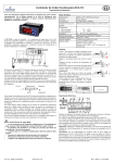
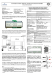
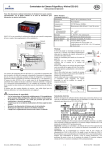
Technical Information Date of last update: 02-08 Ref: D7.10.2/1106-0208/E Application Engineering Europe STARTING METHODS AND UNLOADED START FOR SEMI-HERMETIC COMPRESSORS 1.1 2.1 2.2 2.3 2.3.1 2.3.2 2.4. 2.4.1 2.5 2.5.1 2.5.2 2.5.3 2.5.4 2.6 3.1 5.1 5.1.1 5.1.2 5.1.3 5.2 5.2.1 5.2.2 5.2.3 5.2.4 6.1 6.2 6.2.1 6.2.2 6.2.3 6.2.4 6.2.5 General Remarks ........................................................................................................................................2 Star-Delta Starting Motor Code E Open transition ....................................................................................3 Star-Delta Starting Motor Code E Closed Transition ..................................................................................4 Part Winding Start – Motor Types ...............................................................................................................6 Part Winding Start (2/3:1/3) Motor Code A ...............................................................................................6 Part Winding Start (3/5:2/5) Motor Code B ...............................................................................................7 Resistance Starting (3-phase).....................................................................................................................7 Selection of Starting Resistors ...................................................................................................................7 Other Methods.............................................................................................................................................8 Transformer Start ........................................................................................................................................8 Reactance Starting ......................................................................................................................................9 Soft Starter ( Phase Angle Control )............................................................................................................9 Synchronous Starting ................................................................................................................................10 General Survey / Summary .......................................................................................................................10 Mode of Operation.....................................................................................................................................12 Standard Compressors .............................................................................................................................13 D2S Motor air or suction gas cooled .........................................................................................................13 D3S* Motor suction gas cooled. ................................................................................................................14 D4S - D8S Cylinder position for unloaded start ........................................................................................14 Discus Compressors .................................................................................................................................15 D2D Motor suction gas cooled ..................................................................................................................15 D3D Motor suction gas cooled ..................................................................................................................15 D4D, D6D & D8D Motor suction gas cooled .............................................................................................15 Tandem compressors (e.g.D88SH-5000) Mounting Position of non-return valves ..................................16 Terminal Diagram ......................................................................................................................................17 Circuit Diagram..........................................................................................................................................17 Circuit Diagram..........................................................................................................................................18 Circuit Diagram..........................................................................................................................................19 Circuit Diagram..........................................................................................................................................20 Circuit Diagram..........................................................................................................................................21 Circuit Diagram..........................................................................................................................................22 1/23 D7.10.2/1106-0208/E 1 Terms & Definitions To prevent misunderstanding some terms used in the following sections are explained here. Locked Rotor Current (LRC) same as Locked Rotor Amps (LRA) also shown on compressor nameplate. The LRA is the current measured after 4 seconds when the motor is fixed (cannot rotate) and energised at the upper nominal voltage limit. (e.g. 420V for AWM/D motors at 50 Hz). The LRA may be taken as the maximum starting current for the compressor. Transient phenomena are not considered. Maximum Operating Current (I-OPER. MAX also shown on compressor nameplate). This is the highest value of the motor current occurring in the published operating map for the compressor. This will normally be at the maximum condensing temperature, at the maximum evaporating temperature for the highest pressure refrigerant for which the compressor is released. The value will not correspond exactly to that observed in the data table given in the “Select Software” because the table values are at nominal mean voltage. Also the data table in “Select Software” may not show the full operating envelope, or the compressor may be released for other refrigerants. The voltage at which the maximum current value is taken will normally be the lower nominal voltage limit (e.g. 380V for AWM/D motors, 50 Hz). 1.1 General Remarks Three-phase asynchronous motors with squirrel cage rotors* are used in the semi-hermetic motor compressors made by DWM Copeland. They require no maintenance, are easy to use and are always suitable for Direct-OnLine starting. With D.O.L. starting the motor is switched directly into the mains by means of a switch. The resulting starting current amounts to 4 … 7 times the maximum operating current. (see figure1) *Note: Single-phase asynchronous motors are also available for DK Series compressors. Current Time Figure 1 Direct-On-Line starting current In the case of high powered motors the locked rotor current become so large that they lead to disruptive voltage dips in the mains, which are indicated for example by flickering lighting or side effects in other loads. To prevent these system disturbances power companies limit the permissible size of motors for D.O.L. starting and set a current limit when the motor power is exceeded (nationally and regionally different). What is decisive are the technical conditions of connection stipulated by the power supply Companies. Compliance with the current limitations requires current limiting measures which have to be taken on the electrical installation side and mean a reduction of voltage across the motor terminals (except for Part-Winding Start motors). Since the LRC consumption of three-phase motors reduces in proportion to the voltage, but the motors torques by the square of the voltage, a substantial reduction of current can only be achieved if the load on the motor is reduced at the same time. A minimum starting torque of the compressor has to be observed, the majority of compressors 30%-35% of the torque for D.O.L. start. This is limiting the minimum starting current achievable. 2/23 D7.10.2/1106-0208/E If for example the LRC has to be halved the voltage has to be reduced to 50% of the operating voltage, the torque amounts to only one fourth of the torque at rated voltage and would not longer be enough to start the compressor, even if unloaded start were used. The compressors that are subject to current limitation must therefore be equipped with unloaded start. For exceptions see details of Part Winding Start motors with winding division 2/3-1/3 motor code “A” like compressor D8SJ* - 400X - AWM) to guarantee perfect starting at the minimum required starting torque. 2 Starting methods When power supply companies demand a limit on the LRC there is the question of how to proceed. To provide help in making these decisions we describe in this Technical Information the most important methods that can be used to reduce current and the amount by which the LRC can be reduced. 2.1 Star-Delta Starting Motor Code E Open transition Special wound motors are required for Star-Delta starting. All the ends of each winding must be free so that they can be wired externally. The minimum voltage for which the winding must be dimensioned corresponds to the operating voltage (mains voltage) in a Delta circuit. The DWM Copeland motors which are suitable for this purpose are marked on the nameplate by e.g. 380 - 420V Δ/Y start or 220 - 240V Δ ** / 380 - 420V Y. During the starting phase the motor is connected in Star (circuit diagram 7.2.2). Thus the phase voltage across the motor at the start amounts to only 0.58 (1:√3) of the actually required voltage. The motor is fed with under voltage. The current taken from the mains (Star current IY) drops to one third of the start and operating current that would be needed in a Delta circuit. The torque (MY) which amounts to only one third of the torque in Delta (MΔ) operation (Figures 2a and 2b below) behaves the same way. Note: **Star start of motor compressor only possible with 220-240V mains power. Motor code is shown at compressor nameplate example D3DS5 – 150X - EWM a) Current and b) torque curves with respective Delta and Star connection of asynchronous motor (schematic) Figure 2a ML = Load Torque 2b ns = Synchronous Speed The following preconditions must be met for the motor to start up in star because of the low torque: - The load torque ML must not be greater than 0.3 of the torque in direct starting - During acceleration a speed of more than 0.9 of the synchronous speed should be reached before there is a changeover from Star to Delta. From this it can be seen that unloaded start is absolutely necessary in the case of Star-Delta starting and that there can be no changeover before the motor has accelerated (approximately 1-3 seconds). 3/23 D7.10.2/1106-0208/E Note: Due to the large displacement, the 8 cylinder EW* compressor with unloaded start requires pre-unloading 5 –10 seconds beforehand. The oscillogram in figure 3 shows the current curve of Star-Delta starting. The changeover from Star to Delta must take place at zero current so that there is no arcing short circuit. This short interruption is enough for the speed to drop immediately due to the low amount of centrifugal mass and for the renewed current peak to reach approximately 80% - in unfavourable cases as much as 100% - of the starting current in direct starting. Y connection Figure 3: 2.2 Δ connection Current - Open Transition Star-Delta Starting Motor Code E Closed Transition In normal Star-Delta starting Star contactor K2 and Delta contactor K3 must not be actuated at the same time as that could lead to an arcing short that welds the contacts together or reduces the life of the contactor. The current must be interrupted when there is a changeover (circuit diagram 7.2.2). Closed transition Star-Delta starting avoids this interruption of current by cutting in resistors R7 by way of contactor K10 (circuit diagram 6.2.3). After acceleration of the motor in Star (speed greater than 0.9 synchronous speed) resistors are connected in parallel to the motor winding by contactor K10. This means that the flow of current is not interrupted when the star is opened (K2 opens). Resistors R7 are now in series with the motor winding and are connected to the motor in delta. When delta contactor K3 is actuated, the resistors are shortened and cut out (K10 opens). In oscillograms 4 a, b, c the current curves of a closed-transition Star-Delta start with two different resistances R7, are compared with the current curve of open-transition starting. Figure 4a Star-Delta Start - Open Transition 4/23 D7.10.2/1106-0208/E tp Figure 4b Star-Delta Start - Closed Transition (R7 ≈ 6 Ohms) Figure 4c Star-Delta Start - Closed Transition (R7 ≈ 24 Ohms) t0 = Opening of star point t1 = Cut-In of resistors R7 tu = Open transition tp = Resistors R7 in parallel t2 = Closing of delta contactor K3 When a small resistance R7 (≈ 6 Ohm) cuts in, the current becomes quite large, see figure 4b for current during the period tp. In extreme cases when R7 falls to zero there is a short and the current short circuits. With larger R7 resistance the current drops. The higher the R7 resistance, the smaller the current when the resistors cut in. Compare the currents during the period tp in figures 4b and 4c. The demand for the greatest possible resistance applies only as long as the star point (contactor K2) is closed and resistors R7 are in parallel with the motor winding. When the star point (contactor K2) is opened, resistors R7 are connected to the motor winding in series and a delta connection of the motor is established. However, the effective phase voltage does not correspond to the delta voltage since the latter is reduced by the voltage drop across R7. The larger R7 is, the smaller the effective phase voltage and phase current will be. The motor torque declines, the speed is reduced. In an extreme case, when R7 is infinite and the current equals zero, the star-delta start is with open transition. When the delta contactor is actuated and the resistors shorted out, there is a renewed current peak (t2 in figure 4c), which then (i.e. when R7 is infinite) corresponds to a start with open transition. The smallest possible resistance would be necessary for this short switching phase. The optimum resistance of R7 is in between. With the resistance it is possible to limit the current to approximately 0.4 of the breakaway starting current in direct-on-line starting. R7 (per phase) is calculated on the basis of the following rule of thumb: U R7 = n 3 x 0.33 X Ia Un = Rated motor voltage in delta Ia = Locked-rotor current The resistance of R7 calculated with this formula is a guide value. To take unavoidable tolerances into account we recommend that R7 be kept variable so that you can match the resistance to the system in optimum fashion. Contactor K10 must be dimensioned for the maximum motor voltage (delta voltage) and half the motor power. Due to the thermal load on the resistors and to limit the size it is necessary to keep the duty factor at less than 0.5 second limit the number of switching to 5 per hour and avoid direct restarting. However, the exact duty cycle and number of switching must be requested from the resistor manufacturer or specified in accordance with the requirements of the compressor system. The compressor itself can be started maximum 10 times per hour (3 minutes minimum running time for oil-pressure monitoring and/or faultless supply of oil to the compressor bearings). 5/23 D7.10.2/1106-0208/E 2.3 Part Winding Start – Motor Types Part-winding motors used in our European compressors have 6 separate motor terminals accessible in the terminal box (figure 5 terminals 1–2-3 and 7-8-9). Due to the separate connections the parts of the winding can be separately energised during the starting period drawing only partial current from the mains. For available models see the sales literature. Motor Code ”F” Motor Code”A” Motor Code “B” In respect to the internal motor design there are several types of Part Winding start motors applied. Until August 1983 DWM Copeland used motors with a winding ratio 1/2:1/2 (Motor Code ”F” e.g.” FWM ”). The starting procedure is as follows: Voltage is applied to the first part-winding of the motor to terminals 1, 2, 3. This results in the mains being loaded with the start current of the first part-winding which amounts to 65% of the current in the Direct Start (full winding). Depending upon the starting conditions it is possible that the motor will not start until the second winding is energised. After the full motor winding is connected to the mains (after 1 second + 0.1 second) the full motor start current is reached and the motor will accelerate to full speed. Figure 5 Principle Internal Wiring This motor type was replaced by part-winding motors with a winding ratio 2/3 :1/3 (Motor code “A” e.g.”AWM”) From January 1994 until September 2005 8 cylinder compressors were equipped with an part-winding motor which has the code ”B” e.g. ”BWM”. This replaced the previous motors with motor code ”A”. From September 2005 8 cylinder compressors reverted back to AWM motor code “A”. Note: The motor code can be found on the compressor nameplate. 2.3.1 Part Winding Start (2/3:1/3) Motor Code A This motor winding is divided in a ratio of 2/3:1/3. The current the 1st part-winding draws from the mains when it is switched on amounts to approximately 75% of the LRC in the case of Direct-On-Line starting. Without unloaded nd start, i.e. when there is a great difference in pressure, the motor does not start until the 2 part-winding is cut in after a time lag of 1second + 0,1 second, also loading the mains with the full LRC. The advantage of this type of motor is not realised until “Unloaded Start” is installed. Due to the somewhat higher st LRC of the 1 part-winding and the better magnetic exploitation (compared with a motor with a winding ratio of ½ : ½ ) the motor develops higher starting torque so that it accelerates to the rated speed. When the 2nd part-winding is cut in after a time lag of 1second + 0,1 second the current peak is never greater than 75% of the LRC as in the case of a direct start (Figure 6). With pre-January 1994 8 cylinder compressors motor code “A” with unloaded start, pre-unloading is necessary. September 2005 8-cylinder compressors motor code “A” (AWM) unloaded start is unnecessary. NB: Compressor motor contactor K4 may only switch on when K1 has already closed the contacts. The contactors must be correspondingly interlocked by auxiliary contacts. See connection diagram 6.2.4 . 6/23 D7.10.2/1106-0208/E changeover Figure 6 2.3.2 The Part Winding Start (2/3:1/3) Curve for compressors with unloaded start. Part Winding Start (3/5:2/5) Motor Code B Compared with the code “A” Part-Winding motor the torque has been increased both for DOL starting as well as for PWS. If the motor (without bridges) is supplied with power at terminals 1-2-3 we have in effect a true part-winding start. The start-up current is 68% of the value for across the line starting. Figure 6 shows the principle current curve for PWS with terminal 1-2-3 connected first. The motor accelerates and while connecting terminal 7-8-9 there is no huge current peak. As with the other PWS methods the motor terminals 7-8-9 have to be connected to the mains after 1second + 0.1second. The start of an 8 cylinder compressor with Motor Code B for the A/C application range (R22 or R407C) while using pre-unloading and connecting terminals 7-8-9 first to the mains is only under certain conditions possible and has to be clarified with DWM Copeland case by case. When the motor is started via terminals 7-8-9 (without bridges), the starting current is 54%. 2.4. Resistance Starting (3-phase) The starting methods described in Sections 2.1, 2.2 and 2.3 require motors especially built for this purpose (free winding ends and divided winding). Every 3-phase motor used by DWM Copeland is suitable for resistance starting. The motor must be wired so that it can be started directly. The ohmic starting resistors R6 are cut into the motor leads between motor contactor K1 and the compressor, and shorted out by way of contactor K9 after approximately 0.35 – 0.5 seconds (circuit diagram 7.2.5). The resistances can be sized for any breakaway starting current. The current reduction is only limited by the specified minimum necessary torque so that the motor will start faultlessly. With the unloaded start from DWM Copeland it is possible to limit the current to approximately 55% of the LRA in the case of a direct start. The current peak that occurs when the resistors are shorted out is negligibly small if the speed is greater than 0.9 of the synchronous speed. Intermediate resistor shorted out Figure 7 Current curve with resistance starting. The disadvantage of this method is that the power is dissipated by the resistors in the form of heat. The duty cycle is therefore usually limited to a maximum of 0.5 seconds. Immediate restarting must be avoided and the number of switching limited to 5 per hour (see page 4, 2.2, last paragraph). Please ask for the precise values, number of switching and duty cycle from the resistor manufacturer. DWM Copeland cannot supply any resistors, but we can inform you of the required resistance values on request. 2.4.1 Selection of Starting Resistors This example is supposed to explain how the dropping resistance per phase is calculated: Motor data: D3SS – 100X - EWL Mains Voltage UN = 400 V Locked Rotor Current Ia = 109 A 7/23 D7.10.2/1106-0208/E Torque with direct start at rated voltage Ma Minimum required torque (with load reduction) M ar = 0,3 M a Reduced breakaway starting current (to keep to M ar ) Power Factor with locked rotor cos K = 0,63 I= I a M ar / M a The Impedance of the motor at switch on: ( U ST = phase voltage; Z= U ST = I ST Un = 3 Ia I = 59,7 A I ST = phase current) 400 = 2,12 3 109 The Resistance: R=Zx cosK = 2,12 x 0.63 = 1,33 The Reactance: X=Zx sinK = Z x 1 cosK 2 = 2,12 x 0,776 = 1,646 To limit the breakaway starting current to 59,4 A impedance Z´ is required with the altered resistance R´: Z´ = U ST UN = = I ST 3I 400 = 3,89 3 59,4 R´ = Z ´2 X 2 = 3,87 2 1,64 2 = 3,5 RV = R´-R = 3,5 -1,33 = 2,17 RV = Dropping resistance per phase U ST U ST x 1 cos 2K I Ia 2 Combined to make the formula: RV = 2 U - ST cosK Ia NB: Knowledge of cosK is indispensable for calculating the resistance. Since the value varies depending on the motor manufacturer, it is not indicated here. You can receive it on request. 2.5 Other Methods In addition to the methods mentioned above there are other possibilities of reducing the current mentioned below. 2.5.1 Transformer Start A good but also expensive solution to the problem of reducing the current is provided by a transformer start with which the starting current can be cut to about 33% of the locked-rotor current. An auto- transformer that is connected in Star is used to supply the motor with the voltage required for a perfect start. The locked motor current I existing at reduced voltage conditions drops in linear proportion to the voltage supplied to the 3ph motor. I Ia ü with the voltage transformation ratio ü U1 U2 ( U 1 = primary voltage; U 2 = secondary voltage) However, it is not the motor current, i.e. the secondary transformer current, that loads the mains but the primary current I 1 reduced by the factor of the voltage transformation ratio. In general the following applies to the relationship between the mains current I1 and starting current I a : I1 Ia ü2 8/23 D7.10.2/1106-0208/E As shown in the case of a transformer start the current taken from the mains is not reduced in linear fashion as with the other methods, but by the square of the voltage (if the no load current is not taken into account). In the changeover phase, after the Star circuit of the transformer is opened and before the transformer is shorted out, the motor is still supplied with voltage by part of the transformer, the result being that there is no current interruption. On this phase the part-winding of the transformer functions like a starting reactor. However, experience has shown that during the changeover from the reduced voltage (secondary voltage) to full mains voltage current peaks can occur that are dependent on the difference in the voltages between the mains and motor. The advantage of the high current reduction is lost again, similar to the case with a Y / Δ start. 2.5.2 Reactance Starting The method of starting with starting reactors works on the same principles as resistance starting. Instead of the resistors reactors are cut into the supply circuits, which have to be individually designed for the respective type of compressor and are not as variable as resistors. They have not gained acceptance as a means of limiting the current. 2.5.3 Soft Starter ( Phase Angle Control ) Silicon Controlled Rectifier (SCR) or “Thyristor” are the basis on which soft starting systems for 3ph motors described here are built. SCR switch from “OFF” to “ON” rapidly and remain “ON” until the current through the device falls to zero, at the end of each half-cycle in A.C. supplies. By controlling the switch on point of a thyristor relative to the voltage zero crossing in each half wave, it’s possible to regulate the voltage applied to the motor. v 3 2 1 3 2 1 t Figure 8 ά = firing angle of thyristors The closer the turn on point is to the voltage zero crossing point, the longer the energy is allowed to flow during the half cycle and the higher is the applied voltage to the motor terminals (see figure 8). The soft starter is a voltage phase controlling device. As already described under position 1.1 it is possible to control the starting current of a 3 Phase motor by modulating the supply voltage. Further these devices are providing a voltage ramp soft start, where the voltage is increased from an initial value (which must be high enough to produce the breakaway torque) to the full line voltage in a linear fashion over a user adjustable period of time e.g. 0.4 – 0.8 seconds. 9/23 D7.10.2/1106-0208/E After the motor start, the soft starter is excluded from the supply line by a by-pass. With this method it is possible to adjust the motor torque to the load torque in optimum fashion and control the acceleration time. But one should not forget that the minimum starting current is determined by: Minimum required starting torque at motor shaft (e.g. M ar = 0,3 M a with unloading). Torque producing capability of the motor. Amount of acceleration torque required (all vary with individual compressor type). To get an acceptable reduction of starting current compressors are often used with unloaded start. As with resistance starting, the locked rotor current is then reduced but without energy being dissipated in the form of heat. All thyristor based switching devices produce harmonics towards the motor influencing its characteristics (available torque), and towards the supply line as well. Phase angle control can put a load of harmonics on the mains. The technical connection conditions of the power supply companies are decisive. It is possible to use motors for Direct On Line start but because the frequency cannot be changed, the motor speed cannot be managed. Starting frequency of the Soft Starter recommended by its manufacturer and as well of the compressor must be observed. 2.5.4 Synchronous Starting A static frequency converter is used to regulate the frequency and the voltage in proportion from a minimum value to the reacted value thus achieving a constant acceleration of the motor. Synchronous starting is expensive and therefore not further described here, but it can also be used to regulate the compressor cooling capacity via the compressor speed. Attention: The minimum and maximum speeds of the compressor must be adhered to when regulating compressor power via frequency converters in order to prevent damage, for example by lubrication problems. 2.6 General Survey / Summary Various criteria must be taken into account when deciding which starting method to use. Such as: - What starting current is specified by the “Power Supply Company.” What is specified. What torque is required for perfect starting. How expensive can the system become. Table 1 below may help you to decide which of the normal starting methods is suitable. STARTING METHODS Starting Current While connecting to the mains ! Motor Codes *WM Without Unloading During Start: During Transition With Unloading During Start: During Transition 1st Part Winding 2nd Part Winding Direct-On-Line D.O.L. Star-Delta EWM Y/? *T, F, E, A, B E 100% 33% 100% 100% L1 - L2 - L3 100% Part Winding Start (PWS) FWM 1/2:1/2 AWM 2/3:1/3 BWM 3/5 Connect terminals 1, 2, 3 to Start via the mains first terminals 1, 2, 3 F A B Starting Current (D.O.L.) 67% 100% 75% 100% 33% 67% 75% 80% to100% 100% <75% Running Current (M.O.C.) U-V-W 1-2-3 1-2-3 58% 50% 61%- 67% Z-X-Y 7-8-9 7-8-9 58% 50% 33% - 39% BWM 2/5 Start via terminals 7, 8, 9 B Resistor Start Can be applied on each motor. Connect as with D.O.L. *T, F, E, A, B 68% <68% 54% <54% ~90% <90% 68% <68% 54% <54% ~55% <55% 1-2-3 60% 7-8-9 40% 7-8-9 40% 1-2-3 60% Table 1 Comparison of Starting and Running Current values for different starting methods with and without unloaded start. Note: Load reduction with direct starting is not necessary the locked rotor current is not reduced. 10/23 D7.10.2/1106-0208/E 3 Unloaded Start For D2 and D3 compressors DWM Copeland use an external method of unloaded start using a very short bypass line fitted with a solenoid valve. For D4, D6 and D8 compressors an internal bypass consisting of a special cylinder head is used, this is also controlled by a solenoid valve. By using a bypass the discharge gas is returned to the suction side without substantially increasing the pressure, thus reducing the load on the motor. A non-return valve must be installed in the discharge line to prevent the refrigerant from flowing back from the condenser to the suction side via the bypass. The supplied non-return valves are selected for full load operation, in case of part-load operation a replacement NRV with a weaker spring may be necessary. The unloaded start equipment in the form of a module including the non-return valve can be supplied by DWM Copeland for the single compressor series D2S/D, D3S/D, D4S/D, D6S/D, D8S/D and capacity controlled compressors. The TWIN series of these compressors can be correspondingly equipped with two modules. Unloaded Start is not required with Direct-On-Line Starting. With DWM Copeland 8 cylinder AW* and BW* st compressors Unloaded Start is not required when starting the compressor on the 1 winding (AW* 2/3, BW* 3/5). 4 and 6 cylinder AW* compressors mostly require Unloaded Start when starting the compressor on the first winding (2/3). This is when the compressor requires a high starting torque when the motor load is high (Condensing higher 0 than 50 C). The 8-cylinder AW* motor is different to the 4 and 6-cylinder AW* motor although they are both 2/3, 1/3 part winding start motors. They are with different material design. For the 4, 6-cylinder AW* motor to start loaded it would require a redesign and change of material giving an increase in % LRA part winding start possibly by as much as 10% calling for a review of installation electrics, contactors, cables etc. Mounting Position of Non-Return Valve: A : Compressor Shut-off valve B : Vibration Absorber C : Non Return Valve D : To Condenser Non Return Valve The check valves are to be selected in accordance with the table below and mounted as shown in the illustration above. This selection facilitates quiet operation over a wide application range without chattering noise caused by gas pulsation. If noise should occur during normal or partial load operation it is necessary to match the check valve to the operation conditions. Note: The Non Return Valve (NRVH) for Twin/parallel compressor operation has a stronger spring than the NRV for single compressor operation. 11/23 D7.10.2/1106-0208/E Table 2 Standard Compressors Compressor Non-Return Valve Compressor1) DLH / D2S NRV 22S Ø 22 D4S NRV 22S Ø 22 D44S D3S / D4SJ NRV 28S Ø 28 D44SJ D6SF / L / T NRV 22S Ø 22 D66SF / L / T D6SA / H / J NRV 28S Ø 28 D66SA / H / J D6SK NRV 35S Ø 42 D66SK D8SH / J / K NRV 42S Ø 42 D88SH / J / K 1) also for parallel compressor operation Table 3 2 X NRVH 22S 2 X NRVH 28S 2 X NRVH 22S 2 X NRVH 28S 2 X NRVH 35S 2 X NRVH 42S Ø 22 Ø 28 Ø 22 Ø 28 Ø 42 Ø 42 Discus Compressors Compressor D2D D3DA - 500 / 50X D3D D4D D4DJ D6DL / T D6DH / J D8DL D8DT D8DH D8DJ 1) also for parallel 3.1 Non-Return Valve Non-Return Valve Compressor1) Non-Return Valve NRV 22S Ø 22 D22D 2 X NRVH 22S Ø 22 NRV 22S Ø 22 D33DA - 1000 / 100X 2 X NRVH 22S Ø 22 NRV 28S Ø 28 D33D 2 X NRVH 28S Ø 28 NRV 22S Ø 22 D44D 2 X NRVH 22S Ø 22 NRV 28S Ø 28 D44DJ 2 X NRVH 28S Ø 28 NRV 22S Ø 22 D66DL / T 2 X NRVH 22S Ø 22 NRV 28S Ø 28 D66DH 2 X NRVH 28S Ø 28 NRV 28S Ø 28 D88DL 2 X NRVH 28S Ø 28 NRV 28S Ø 28 D88DT 2 X NRVH 28S Ø 28 NRV 35S Ø 42 D88DH 2 X NRVH 35S Ø 22 NRV 35S Ø 42 D88DJ 2 X NRVH 35S Ø 28 compressor operation Mode of Operation When the compressor is switched on, the solenoid valve opens the bypass and holds it open during the starting phase. After completion of the starting procedure the solenoid valve closes the bypass. That is after: Change over from Star to Delta nd Energising of the 2 part-winding Shorting out of the starting Resistors or the Soft Start device (circuit diagram 6.2.2 for the block diagram of the electric circuit of solenoid valve Y3). A non return valve must be installed in the discharge line to prevent the refrigerant flowing back from the condenser to the suction side via the bypass line. Care must be taken that in systems with a pump down circuit, solenoid valve Y3 must always be closed during pump down. 4 Selection Information DWM Copeland cannot supply any unloaded start module for small, single stage and two stage compressors (smaller than type D2S/D2D). In these special cases the owner must provide pressure reduction. The diameter of the bypass line and solenoid valve should be selected 1 size smaller than the discharge gas line. The bypass line between the discharge and suction line must be as short as possible to keep the pressure drop small. As a guideline the pressure drop across the bypass line and magnetic valve should be smaller than 3 bar, otherwise there would be not sufficient load reduction and the motor would not accelerate because of the high counter-torque. Care must be taken to avoid the accumulation of condensate and oil in the bypass line. 12/23 D7.10.2/1106-0208/E Piston compressors are producing gas pulsations and these pulsations can affect the non return valve in the discharge line causing chattering of the valve and a reduction in life expectancy. The use of a discharge muffler may be come necessary. The manufacturers recommendation must be followed for the valve selection. This is very important if the compressor has to operate with capacity control, in a large application range over a large pressure ratio, or as a two-stage internal compounded compressor. 5 Installation Instructions The following explanations and drawings serve as an indication for the arrangement of the unloaded start equipment at the compressor. 5.1 Standard Compressors 5.1.1 D2S Motor air or suction gas cooled For limits see application envelope shown in ”Select” found on our website www.ecopeland.com a) Unloaded start - Components b) Mounting position - Motor air cooled c) Mounting position - Motor suction gas cooled 13/23 D7.10.2/1106-0208/E 5.1.2 D3S* Motor suction gas cooled. Unloaded start equipment – Parts 5.1.3 Mounting position D4S - D8S Cylinder position for unloaded start D4S … D6S … D8S … Control Solenoid Valve (Marking = * 705 RA 001) 14/23 D7.10.2/1106-0208/E 5.2 Discus Compressors 5.2.1 D2D Motor suction gas cooled Unloaded start equipment – Parts 5.2.2 D3D Motor suction gas cooled Unloaded start equipment – Parts 5.2.3 Mounting position Mounting position D4D, D6D & D8D Motor suction gas cooled a) Unloaded start equipment 15/23 D7.10.2/1106-0208/E b) Unloaded start mounting position 5.2.4 Tandem compressors (e.g.D88SH-5000) Mounting Position of non-return valves 1 = Non-return valve compressor I 2 = Control valve of internal unloaded start equipment 3 = Non return valve compressor II 4 = Muffler (4, 6 & 8 cylinder compressor) 5 = Connection common discharge line 16/23 D7.10.2/1106-0208/E 6 Electrical Schematic Diagrams and Circuit Diagrams General wiring diagrams, circuit diagrams and respective operating sequence plans are presented on the following pages for each starting method described, but without any claim to being complete or comprehensive. With the exception of Direct On Line Starting all the diagrams are with unload start. In addition one example each is provided for preliminary load reduction (for series D8S) and a pump-down circuit. A limit on the frequency of operations is not taken into account in the circuit diagrams but it is always required for protection of the resistors in the case of starting methods in accordance with sections 2.2 and 2.4. This limit is also required when more than 15 switchings per hour are caused by a thermostat or other sources. You will find explanations of applied symbols on the last page. All rights and the right to make technical changes are reserved. No responsibility is taken for the correctness of the information and no claims can be demanded from these documents. 6.1 Terminal Diagram Electronic module INT 69 or INT 69 TM for motor protection M1 L1 & N = Voltage Supply* 220-240V – 40..60H 1 + 2 = Connection of thermistors 12 = Signal lamp 11 + 14 = Control Circuit K = Relay, making capacity 300 VA, at cosφ = 0,3 *Other voltage on request 6.2 Circuit Diagram Oil Pressure Switch (OPS - differential) 17/23 D7.10.2/1106-0208/E 6.2.1 Circuit Diagram Direct-On-Line Start 18/23 D7.10.2/1106-0208/E 6.2.2 Circuit Diagram Star Delta Start (Y/ Δ) with a pumpdown cycle, oil pressure safety control and unloaded start I 1 II K 1.1 K 1.2 K 1.21…23 K 1.8 K 2.27…29 K 2.9 K 2.10 K 3.24…26 K 3.6 K 3.9 K 3.10 K 11.6 K 11.11 Y3 TM09 7.3 I II 1 ■ □ Star (Y) Start 1 - 3 seconds Delta (Δ) Operation Change over period approximately 0.02 – 0.1 second Contacts respective valve closed Contacts respective valve opened 19/23 D7.10.2/1106-0208/E 6.2.3 Circuit Diagram Star Delta Start (Y/ Δ), closed transition with unloaded start I II 1 K 1.1 K 1.2 K 1.21…23 K 1.5 K 1.6 K 2.27…29 K 2.7.1 K 2.7.2 K 3.24…27 K 3.5 K 3.7 K 3.9 K 3.11 K 10.30…32 K 11.10 K 11.12 K 15.8 K 15.9 Y3 TM 09 7.4 I II 1 ■ □ Star (Y) Start 1 - 3 seconds Delta (Δ) Operation Change over period approximately 0.1 – 0.5 second Contacts respective valve closed Contacts respective valve opened 20/23 D7.10.2/1106-0208/E 6.2.4 Circuit Diagram Part Winding Start Pre-unloaded Attention ! 8 cylinder compressors with StarDelta start (EW*) require preunloading. With the introduction of new motors in August 2005, the AW* motor replacing the BW* motor (8 cylinders) retain the ability to start loaded (without unloading) on the 2/3 winding first. I II III K 1.1 K 1.2 K 1.21…23 K 1.9 K 1.10 K 4.24…26 K 4.5 K 4.7 K 4.11 K12.10 K 14.7 K 14.8 Y3 TM09 7.5 I II III ■ □ Pre-unloading 5 – 10 seconds First part winding 1.0 + 0.1 seconds Both part windings Contacts respective valve closed Contacts respective valve opened 21/23 D7.10.2/1106-0208/E 6.2.5 Circuit Diagram I II K 1.1 K 1.2 K 1.21…23 K 1.6 K 9.24…26 K K 9.6 9.7 K K 9.7 9.9 K K 9.9 13.8 K Y313.8 Y3 TM09 7.6 Resistance Starting - unloaded start I II ■ □ Resistance Starting <0.5 seconds Nominal operation Contacts respective valve closed Contacts respective valve opened 22/23 D7.10.2/1106-0208/E 6.2.6 Applied Symbols according to DIN 40719 A1 A2 B1 F1 F3 F31 F32 F4 F5 F51 F6 F7 F8 H1 K1 K2 K3 K4 K9 K10 K11 K12 K13 K14 K15 M1 Q1 R1 R2 R5 R6 R7 S1 Y1 Y3 = = = = = = = = = = = = = = = = = = = = = = = = = = = = = = = = = = = Electronic module for M1 Oil pressure switch Room thermostat Fuse for control circuit (characteristics must be related to maximum load of control mechanism) High Pressure Switch Pressure cut-out Safety pressure cut-out Low pressure switch Trip timer inside A2 Differential pressure switch in A2 Fuse M1 Fuse M1 Fuse M1 Signal Lamp A1 Contactor M1 Y contactor M1 Δ contactor M1 Contactor M1 for second part-winding Contactor for R6 Contactor for R7 Time delay relay 1…3 s for Y/Δ start Time delay relay 1 s ± 0.1 for part-winding start Time delay relay for resistance starting (R6) Time delay relay for pre-unloaded start 5…10 s Time delay relay for Y/Δ start closed transition Compressor motor Main switch Resistor in A2 Crankcase heater Thermistors in M1 Intermediate Resistors Resistors Y/Δ start closed transition Auxiliary switch, if crankcase heater should heat prior to operation of the compressor Solenoid valve liquid line Solenoid valve unloaded start M1 23/23