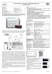
1
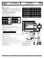
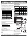
Replacement for A6.5.070 / 07
Wiring Diagram
Power supply
Transformer
Fuse
1.0 A
Power
output for
second
driver in
system, if
available
Digital output
alarm relay
Valve is opening
*) These terminals are for use with specific
controller and should not be wired.
**) Digital input: The contact should be
wired based on system operation
configuration:
a) Direct start and stop of compressor:
The contact will be activated/deactivated as
the first stage compressor starts or stops.
b) Pump down:
The contact will be activated/deactivated as
cooling demand activated/deactivated. The
compressor will be activated/deactivated by
low pressure switch.
Date: 21.04.2006
Blue
Brown
Black
Valve is closing
White
!
Safety instructions:
• Read operating instruction thoroughly. Failure to comply can result in
device failure, system damage or personal injury.
• It is intended for use by persons having the appropriate knowledge and skill.
• Switch off all voltages / currents before cabling.
• Comply with local electrical regulations when wiring
• Do not operate system before all cable connections are completed.
• Do not apply 110/220/230 V to any terminal of driver module
Installation and wiring
• Install EXV in system per operating instructions of valve.
• Make sure that driver type matche to the type of valve and refrigerant in the
system as follows:
Driver module type
Valve
Refrigerant
EXD-S05
EX5
R22
EXD-S06
EX6
R22
EXD-S07
EX7
R22
EXD-S08
EX8
R22
EXD-S15
EX5
R407C
EXD-S16
EX6
R407C
EXD-S17
EX7
R407C
EXD-S18
EX8
R407C
EXD-S25
EX5
R134a
EXD-S26
EX6
R134a
EXD-S27
EX7
R134a
EXD-S28
EX8
R134a
EXD-S35 / EXD-S35S
EX5
R404A
EXD-S36 / EXD-S36S
EX6
R404A
EXD-S37
EX7
R404A
EXD-S38
EX8
R404A
EXD-S45
EX5
R410A
EXD-S46
EX6
R410A
• Install Driver Module, pressure transmitter and temperature sensor.
• Set-up all wire connections as shown wiring diagram.
• Recommended wire cross section between 0.5 mm2 and 2.5 mm2.
• Keep sensor cables separate from all other power and driver lines.
Start-up procedure:
• Do not apply voltage to the driver before completion of wiring.
• Do not operate the driver and valve when the system is under vaccum or
without refrigerant except for closing valve before charging of system.
• Vacuum the entire system.
• Warning: Alco EXVs are delivered at half open position. Do not charge
system before closure of valve.
• Apply supply voltage to driver module for the following times without
activation of digital input to terminals ID/Avss of driver module:
Valve
Time, seconds
EX5/EX6
Min: 2
Max: 30
EX7/EX8
Min: 6
Max: 30
• After closure of valve, intrup power supply to driver module and charge the
system with refrigerant.
• Start the system and check the superheat and operating conditions.
Technical data, power supply:
• Main supply voltage: 24V AC (+10%, -15%), 50-60Hz; 24 VDC (+10%, -0%).
Power supply line to driver to be protected by 1.0 A external fuse.
• Use a safety class II transformer. Minimum power required 20VA.
• Emergency supply voltage (from ECP-024): approx. +18 V DC.
Technical data, inputs:
• 1 analogue input 4-20mA for pressure transmitter, measurement range -0.8 to 7
bar (PT4-07S) or 0 to 18 bar (PT4-18S).
• 1 NTC analogue input, very fast responce with precision ±0.5K
• 1 digital input for 5V/5mA insulated contact (potential free/dry contact)
Outputs:
• 4 current-outputs for stepper motor of EX5/EX6/EX7/EX8.
Nominal current: 0.5A for EX5/EX6, 0.75A for EX7 and 0.8A for EX8.
Maximum cable length: 6 meter AWG20/22.
• 1 digital output for alarm relay, rated power 10VA, 0.5A resistive at 24VAC.
Contact normally open. (The contact is closed under normal operating
conditions; it is open under alarm conditions or when there is no power supply).
Number of automatic operating cycles: (relay) 100.000.
• 1 +24VDC supply output for PT4.
Uninterruptible power supply ECP-024
• Power supply voltage: 24 VAC ± 10%
• Power outputs: Two, each +18VDC
Indicator and Error Messages
Description
Priority Valve opens Valve closes
Power
Alarm
level green LED Green LED green LED red LED
Off
Off
Off
Off
Off
Power supply
On
Off
Valve is opening
Blink
Off
On
Off
Valve is fully open
On
Off
On
Off
Valve is closing
Off
Blink
On
Off
Valve is fully close
Off
On
On
Off
EEPROM read err. 1, High
Off
Off
On
Blink
Motor connection
2
Blink
Blink
On
On
error
Pressure and or
3
Off
Blink
On
On
temperature
probe(s) error
EEPROM write error 4, Low
Off
Off
On
On
Note: In case where more than one alarm is active, the alarm with higher priority
is displayed.
White
Brown
EXD-S.. Stand Alone Driver Modules are for driving ALCO stepper motor
driven electronic expansion valves series EXV-5, -6, -7, -8. These instructions
are for versions supplied after Datecode 2803.
Document Nr.: A6.5.070 / 08
GB
Normal Operation
Tel.: 07151 509-0 - Fax.: -200
www.alco-controls.com – [email protected]
Operating Instructions
Stand Alone Driver Module EXD-S Series
for Electronic Expansion Valves EX5 … EX8
Alarm
ALCO CONTROLS
Emerson Electric GmbH & Co OHG
Heerstr.111 - D 71332 Waiblingen
Electrical Electrical
connection plug
EX5-Nxx
connection
PCN: 862970
Replacement for A6.5.070 / 07
Anzeige und Fehlermeldungen
Alarm
Beschreibung
Prior. EXV öffnet EXV schließt Netzspg.
Stufe grüne LED grüne LED grüne LED rote LED
Aus
Aus
Aus
Aus
Aus
Eingeschaltet
Ein
Aus
EXV öffnet
Blinkt
Aus
Ein
Aus
EXV geöffnet
Ein
Aus
Ein
Aus
EXV schließt
Aus
Blinkt
Ein
Aus
EXV geschlossen
Aus
Ein
Ein
Aus
EEPROM Lesefehler 1, hoch
Aus
Aus
Ein
Blinkt
Verbindungsfehler
2
Blinkt
Blinkt
Ein
Ein
Schrittmotor
Ausfall Druck- oder
3
Aus
Blinkt
Ein
Ein
Temperaturfühler
4,niedrig
EEPROM
Aus
Aus
Ein
Ein
Schreibfehler
NB: Treten mehrere Alarmbedingungen gleichzeitig ein wird der Alarm mit der
höchsten Prioritätsstufe angezeigt.
Verdrahtungsplan
Versorgungsspannung
Transformator
Sicherung
Ausgang zu
zweitem
Regler,
wenn
verfügbar.
1,0 A
Digital Ausgang
Alarm Relais
Ventil öffnet
*) Die Klemmen sind reserviert. Nicht
verdrahten!
**) Anschluß des Kontakts je nach Systemkonfiguration:
a) Verdichterbetrieb: Kontakt wird geschlossen,
wenn der erste Verdichter anläuft –
geöffnet, wenn er ausgeschaltet wird.
b) Abpumpen Schaltung: Kontakt schließt/öffnet
je nach Kältebedarf. Der Verdichter wird von
einem Niederdruckschalter gesteuert.
Date: 21.04.2006
blau
braun
schwarz
Ventil schließt
weiss
!
Sicherheitshinweise:
• Lesen Sie bitte die Betriebsanleitung gründlich. Nichtbeachten kann zum
Versagen, zur Zerstörung der Anlage oder zu Verletzungen führen.
• Der Einbau darf nur von geschulten Fachkräften vorgenommen werden.
• Vor Verdrahtung muß die Anlage stromlos geschaltet werden.
• Beachten Sie bitte die einschlägigen Vorschriften für die Installation
elektrischer Anlagen
• Die Anlage darf erst dann in Betrieb genommen werden, wenn alle
Verbindungen hergestellt sind.
Installation und Verdrahtung EXD-S…
• Elektronisches Expansionsventil (EXV) gemäß jeweiliger Betriebsanleitung
installieren.
• Passende Schrittmotorsteuerung in Abhängigkeit von Expansionsventil und
Kältemittel gem. folgender Tabelle einsetzen:
Überhitzungsregler
Expansionsventil
Kältemittel
EXD-S05
EX5
R22
EXD-S06
EX6
R22
EXD-S07
EX7
R22
EXD-S08
EX8
R22
EXD-S15
EX5
R407C
EXD-S16
EX6
R407C
EXD-S17
EX7
R407C
EXD-S18
EX8
R407C
EXD-S25
EX5
R134a
EXD-S26
EX6
R134a
EXD-S27
EX7
R134a
EXD-S28
EX8
R134a
EXD-S35 / EXD-S35S
EX5
R404A
EXD-S36 / EXD-S36S
EX6
R404A
EXD-S37
EX7
R404A
EXD-S38
EX8
R404A
EXD-S45
EX5
R410A
EXD-S46
EX6
R410A
• Überhitzungsregler, Drucktransmitter und Temperatursensor gemäß
Verdrahtungsplan anschließen
• Empfohlener Kabelquerschnitt: 0,5 mm2 … 2,5 mm2.
• Fühlerleitungen sind getrennt von allen anderen Stromkabeln zu verlegen.
Inbetriebnahme
• Anlage darf nur vollständig verdrahtet eingeschaltet werden.
• Expansionsventil darf zum Schließen ohne Kältemittel max. 30 sec betrieben werden
• Anlage evakuieren.
• Achtung: neue EXV Expansionsventile werden halb geöffnet ausgeliefert.
Anlage darf jedoch nur bei geschlossenem Expansionsventil befüllt werden!
• Elektronisches Expansionsventil schließen:
Überhitzungsregler während folgender Schließzeit einschalten, ohne den
Verdichter zu starten (Digitaleingang ID/AVss auf niedrigem Potential):
Expansionsventil
Schließzeit in sec.
EX5/EX6
Min: 2
Max: 30
EX7/EX8
Min: 6
Max: 30
• Wenn das Expansionsventil geschlossen ist, Versorgungsspannung abschalten
und Anlage mit Kältemittel befüllen.
• Anlage starten und Überhitzung und Betriebsbedingungen prüfen.
Technische Daten Stromversorgung:
• Versorgungsspannung: 24V AC (+10%, -15%), 24V DC (+10%, -0%).
Versorgungsleitung mit 1,0 A absichern.
• Transformator Klasse II verwenden, Nennleistung: min. 20VA.
• Batteriespannung (von ECP-024): ca. +18 V=
Eingänge:
• 1 Analogeingang 4-20mA für Drucktransmitter mit Meßbereich -0.8…7 bar
(PT4-07A) oder 0…18 bar (PT4-18A).
• 1 Analogeingang für NTC Temperaturfühler, kurze Reaktionszeit, Genauigkeit ±0.5K
• 1 Digitaleingang für 5V/5mA (potentialfrei)
Ausgänge:
• 4 Stromausgänge für Schrittmotoransteuerung von EX5 / EX6 / EX7 / EX8.
Nennstrom: 0.5A bei EX5 und EX6; 0,75A bei EX7, 0,8A bei EX8.
• Maximale Kabellänge: 6 Meter AWG20/22.
• 1 Digitalausgang für Alarmrelais, Schaltleistung 10VA, 0.5A / 24VAC bei
Ohm’scher Last. Kontakt ist stromlos geöffnet. (Im Normalbetrieb ist der
Kontakt geschlossen und öffnet sich nur bei Alarm oder Stromausfall).
Anzahl der Kontaktwechsel (Relais): 100 000.
• 1 Ausgang mit +24VDC Versorungsspannung für PT4.
Unterbrechungsfreie Stromversorgung ECP-024
• Versorgungsspannung: 24 VAC ± 10%
• Ausgänge: 2 mit jeweils +18VDC
weiss
braun
Die elektronischen Überhitzungsregler der Baureihe EXD-S werden zusammen
mit den elektronischen Expansionsventilen EX-5, -6, -7, -8 eingesetzt. Diese
Anleitung gilt nur für Geräte ab Datumcode 2803.
Document Nr.: A6.5.070 / 08
D
Normal Betrieb
Tel.: 07151 509-0 - Fax.: -200
www.alco-controls.com – [email protected]
Betriebsanleitung
Elektronische Überhitzungsregler EXD-S
für elektronische Expansionsventile EX5 … EX8
Alarm
ALCO CONTROLS
Emerson Electric GmbH & Co OHG
Heerstr.111 - D 71332 Waiblingen
Anschluss- Anschluss
stecker
stecker
EX5-Nxx
PCN: 862970
ALCO CONTROLS
Emerson Electric GmbH Co OHG
Heerstr. 111 – D 71332 Waiblingen
Návod k montáži
www.alco-controls.de; [email protected]
Signalizace poruch a provozních stavů
Poruchy (červená) a provoz (zelená) signalizují kontrolky LED
!
Document Nr.: A6.5.070 / 08
Replacement for A6.5.070 / 07
P
O
R
U
C
H
Y
popis
vypnuto
zapnuto napájení
ventil otevírá
ventil plně otevřen
ventil zavírá
ventil zcela uzavřen
EEPROM čtení
motor bez povelu
závada čidel
EEPROM zápis
st.
1
2
3
4
otevírá
bliká
svítí
bliká
-
zavírá
bliká
svítí
bliká
bliká
-
napáj
+
+
+
+
+
+
+
+
+
alarm
bliká
+
+
+
St.: stupeň důležitosti – 1 nejvyšší, při více poruchách najednou signalizuje vždy
vyšší důležitost
Schema zapojení
napájeni
trafo
pojistka
1,0 A
Power
output for
second
driver in
system, if
available
digitálni výstup
alarmové rele
ventil otevirá
*) Poznámka: pomocný vstup označený
**) se používá například od ovládání
kompresoru – ventil je sladěn se startem
kompresoru, nebo při použití odsávání při
zastavení (pump-down) spíná kontakt
termostat, zatím co kompresor je ovládán
nízkotlakým presostatem.
Date: 21.04.2006
modry
cerný
ventil zavirá
hnedy
Montáž a připojení elektro
• Namontovat ventil EX podle návodu k jeho montáži
• Zkontrolovat správné přiřazení modulu k ventilu a chladivu
modul
ventil
chladivo
modul
ventil
chladivo
EXD-S05
EX5
EXD-S25
EX5
R22
R134a
EXD-S06
EX6
EXD-S26
EX6
EXD-S07
EX7
EXD-S27
EX7
EXD-S08
EX8
EXD-S28
EX8
EXD-S15
EX5
EXD-S35
EX5
R407C
R404A
EXD-S16
EX6
EXD-S36
EX6
R507
EXD-S17
EX7
EXD-S37
EX7
EXD-S18
EX8
EXD-S38
EX8
EXD-S45
EX5
R410A
EXD-S46
EX6
• Namontovat modul, snímač tlaku, čidlo teploty a záložní zdroj
• Propojit jednotlivé prvky podle schématu
• Doporučený průřez vodičů je mezi 0,5 až 2,5 mm2
Spouštění
• Pokud není provedeno úplné propojení nesmí se připojit napětí
• Modul a ventil se nesmí provozovat pod vakuem a nebo bez chladiva – výjimka
je zavření ventilu před plněním okruhu
• Odsát okruh
• Pozor: ventil EX je dodáván v polootevřeném stavu – napřed se musí uzavřít a
pak plnit okruh
• Připojit napájení k modulu bez sepnutí svorek ID-Avss po dobu:
EX5 a EX6
min. 2 max 30 vteřin
EX7 a EX8
min. 6 max 30 vteřin
• Po uzavření ventilu odpojit napájení a plnit chladivo
• Připojit napájení a spustit zařízení – nastavit přehřátí a provoz
Technické údaje napájení
• Hlavní napájení 24 V st +10%, -15%; 24 V ss +10%, -15% ochrana pojistkou
1,0 A
• transformátor třídy II nejméně 20 VA
• záložní napájení z baterie +18V ss
Vstupy
• 1 x 4 až 20 mA ze snímače tlaku –80 až 700 kPa (0-1,8MPa)
• 1 x NTC teplotní čidlo rychlé, přesnost ±0,5 K
• 1 x pomocný digivstup 5V / 5mA izolovaný, bez potenciálu
Výstupy
• 4 x proudové pro krokový motor : 0,5 A pro EX5/6, 0,75A pro EX7 a 0,8 A pro
EX8, max. délka vodiče 6 m (AWG20/22)
• 1 x alarmové relé, 10 VA, 0,5A při 24V st, kontakt při poruše nebo při výpadku
napájení rozpíná
• 1 x 24 V ss pro dobíjení záložního zdroje a napájení snímače tlaku (PT4)
Záložní zdroj ECP-024
• napájení – dobíjení 24 V ss
• výstup +18 V ss pro 2 moduls EXD
P
R
O
V
O
Z
bily
hnedý
bezpečnostní pokyny:
• Prostudujte pečlivě návod. Chybné použití může způsobit vážné poruchy
zařízení I poranění osob.
• Montáž smí provádět pouze osoba s odpovídající kvalifikací a zkušeností
• Před otevřením jakékoliv části okruhu je nutno vnitřní tlak vyrovnat s
atmosférickým
• Je nutno zkontrolovat elektrické parametry připojované sítě s údaji
přístroje. Montáž nesmí být prováděna pod napětím.
• Nikdy se nesmí překročit zkušební přetlak
• Nepoužívat napětí 110/230 V na žádnou část modulu
bily
Samostatný ovládací modul EXD-S pro elektronické krokové expanzní ventily
ALCO řady EX5 až EX8
CZ
Řídící modul EXD-S
k ventilům EX5 …EX8
kabel
svorkovnice
EX5-Nxx
PCN: 862970
ALCO CONTROLS
Instrukties voor het gebruik
Emerson Electric GmbH & Co OHG
Elektronische oververhittingsregelaar EXD-S
Heerstr.111 - D 71332 Waiblingen
voor elektronische expansieventielen EX5..EX8
Tel.: 07151 509-221 - Fax.: -200
De elektronische oververhittingregelaar EXD-S worden tesamen met de
normale bedrijfscondities, en is open bij alarm of spanningsuitval). Aantal
elektronische expansieventielen EX5, -6, -7, -8 ingezet. Deze gebruiksaanwijzing
schakelingen (Relais) 100 000.
is bedoeld voor apparaten vanaf datumcode 2803
• 1 +24VDC voeding voor PT4.
Noodstroomvoorziening ECP-024
! Veiligheidsinstrukties:
• Voedingsspanning: 24 VAC ± 10%
• Uitgangen: Twee, elk +18VDC
• Neem het installatievoorschrift grondig door. Verzuim hiervan kan aanleiding
zijn tot storingen of
beschadiging van de apparatuur
of
andere
installatiecomponenten , of leiden tot persoonlijk letsel.
Indicatoren en foutmeldingen
• De montage mag uitsluitend door vakbekwame personen worden uitgevoerd.
Beschrijving
Niveau Ventiel open Ventiel sluit Spanning
Alarm
• Maak voor montage de installatie stroomloos.
Groene LED Groene LED
Groene
Rode
• De geldende elektrische voorschriften dienen in acht te worden genomen.
LED
LED
• Neem de installatie pas in bedrijf NADAT ALLE bekabeling is
Uit
Uit
Uit
Uit
Uit
aangesloten.
Voedingsspanning
Aan
Uit
• Sluit geen 110/220/230 V aan op enige klem van de regelaar.
Ventiel opent
Knippert
Uit
Aan
Uit
Installatie en bekabeling:
Ventiel
volledig
Aan
Uit
Aan
Uit
• Installeer het elektronische expansieventiel conform de meegeleverde
open
installatie-instrukties.
Ventiel sluit
Uit
Knippert
Aan
Uit
• Gebruik de juiste oververhittingsregelaar conform onderstaande tabel:
Ventiel volledig
Uit
Aan
Aan
Uit
Oververhittingsregelaar
Ventiel
Koudemiddel
gesloten
EXD-S05
EX5
R22
EEPROM leesfout.
1,
Uit
Uit
Aan
Knippert
EXD-S06
EX6
R22
Hoog
EXD-S07
EX7
R22
Fout in verbinding
2
Knippert
Knippert
Aan
Aan
EXD-S08
EX8
R22
naar de
EXD-S15
EX5
R407C
stappenmotor
EXD-S16
EX6
R407C
Fout in temperatuur
3
Uit
Knippert
Aan
Aan
EXD-S17
EX7
R407C
en/of drukopnemer
EXD-S18
EX8
R407C
EEPROM schrijffout 4, Laag
Uit
Uit
Aan
Aan
EXD-S25
EX5
R134a
Alarm
Normaal bedrijf
NL
Document Nr.: A6.5.070 / 08
Replacement for A6.5.070 / 07
Bekabelingsschema:
Voedingsspanning
Transformator
Zekering
1.0 A
Uitgang
voor een
tweede
regelaar
Digitale uitgang
Alarm relais
Ventiel opent
*) Deze klemmen zijn gereserveerd, niet
gebruiken.
**) Digitale ingang: bekabelen conform de
systeemvereisten:
a) Directe start en stop van de compressor:
Het contact wordt gesloten zodra de eerste compressor start, en geopend zodra de compressor
stopt.
b) Pump down:
Het contact wordt geopend/gesloten afhankelijk
van de koudebehoefte. De compressor wordt
middels een separate drukschakelaar
gestart/gestopt.
Date: 21.04.2006
Blue
Brown
Black
Ventiel sluit
White
Inbedrijfname:
• Schakel de installatie pas in NADAT ALLE bekabeling is aangsloten.
• Stel het systeem niet in bedrijf zolang het systeem onder vacuum staat, en er
geen koudemiddel in het systeem is gevuld, behalve voor het sluiten van het
ventiel tijdens vullen.
• Vacuumeer het gehele systeem.
• Let op:: Alco elektronisceh expansieventielen EXVworden geleverd in half
open positie. De installatie mag alleen bij gesloten ventiel gevuld worden.
• Stel de regelaar gedurende onderstaande tijd in werking, zonder de compressor
te starten (digitale ingang ID/AVss open):
Ventiel
Tijd, seconden
EX5/EX6
Min.:2
Max.:30
EX7/EX8
Min.:6
Max.:30
• Na het sluiten van het ventiel dient de spanning van de regelaar te worden
afgehaald, en kan het systeem met koudemiddel gevuld worden.
• Stel het systeem in bedrijf en controleer de oververhitting en overige
bedrijfscondties.
Technische gegevens Voedingsspanning:
• Minimum voedingsspanning: 24 V AC (+10%, -15%), 50-60Hz; 24 V DC
(+10%, -0%). Afzekeren met 1.0 A.
• Gebruik een transformator klasse II. Minimum vermogen 20VA.
• Noodstroomvoorziening (van ECP-024): circa +18 V DC.
Ingangen:
• 1 analoge ingang 4-20mA ten behoeve van drukopnemer, meetbereik -0.8 tot 7
bar (PT4-07A) of 0 tot 18 bar (PT4-18A).
• 1 NTC analoge ingang, voor temperatuuropnemer, snelle reactietijd, precizie
±0.5K
• 1 digitale ingang voor 5V/5mA potentiaalvrij.
Uitgangen:
• 4 stroom-uitgangen voor stappenmotor van EX5/EX6/EX7/EX8.
Nominale stroom: 0.5A voor EX5/EX6, 0.75A voor EX7 en 0.8A voor EX8.
Maximum kabellengte: 6 meter AWG20/22.
• 1 digitale uitgang voor alarmrelais schakelvermogen 10VA, 0.5A Ohmse
belasting bij 24VAC. Normaal geopend contact. (Het contact is gesloten bij
Opm.: Indien er meerdere alarmen gelijktijdig actief zijn wordt het alarm met de
hoogste prioriteit aangegeven.
White
Brown
EXD-S26
EX6
R134a
EXD-S27
EX7
R134a
EXD-S28
EX8
R134a
EXD-S35 / EXD-S35S
EX5
R404A
EXD-S36 / EXD-S36S
EX6
R404A
EXD-S37
EX7
R404A
EXD-S38
EX8
R404A
EXD-S45
EX5
R410A
EXD-S46
EX6
R410A
• Installeer de regelaar, de drukopnemer en de temperatuuropnemer volgens het
bekabelingsschema.
• Aanbevolen kabeldoorsnede tussen 0.5 mm2 en 2.5 mm2.
• De voelerbekabeling is seperaat van andere bekabeling te verleggen.
Elektrische aansluit
aansluiting stekker
EX5-Nxx
connection
PCN: 862970
ALCO CONTROLS
Emerson Electric GmbH & Co OHG
Heerstr.111 - D 71332 Waiblingen
Tel.: 07151 509-0 - Fax.: -200
www.alco-controls.com – [email protected]
Instrucciones de Operación
Los módulos de la serie EXD-S.. se utilizan para controlar las válvulas de
expansión electrónicas ALCO de motor paso a paso EXV-5, -6, -7, -8. Estas
instrucciones sólo son validas para unidades cuyo código de fabricación sea
posterior a 2803.
!
E
Módulo de Control Autónomo Serie EXD-S
para Válvulas de Expansión EX5 … EX8
Salidas:
4 salidas de corriente para el motor paso a paso de EX5/EX6/EX7/EX8.
Intensidad nominal: 0.5A para EX5/EX6, 0.75A para EX7 y 0.8A para
EX8. Máxima longitud del cable: 6 metros AWG20/22.
• 1 salida digital para relé de alarma, Potencia nominal 10VA, 0.5A resistiva a
24VAC. Contacto normalmente abierto. (El contacto permanece cerrado bajo
condiciones de trabajo nominal; se abre en condiciones de alarma o cuando no
hay alimentación eléctrica). Número de ciclos de trabajo: (relé) 100 000.
• 1 salida de +24VDC para PT4.
Sistema de alimentación ininterrumpida ECP-024
• Alimentación: 24 VAC ± 10%
• Salidas: dos, cada una de +18VDC
Indicadores y Mensajes de error
Nivel
Valv. Abre Valv.cierra Aliment. Alarma
Descripción
prioridad
LED verde LED verde LED verde LED rojo
Off
Off
Off
Off
Off
Alimentación
On
Off
Valv está abriendo
Intermitente
Off
On
Off
Valv.cerrada compl.
On
Off
On
Off
Valv está cerrando
Off
Intermitente
On
Off
Valv.abierta compl
Off
On
On
Off
Error lect.EEPROM 1, Alta
Off
Off
On
Interm.
Error conexión
2
Intermitente Intermitente
On
On
motor
Presión y o
3
Off
Intermitente
On
On
temperatura (s)
error sensores
Error escr.EEPROM 4, Baja
Off
Off
On
On
Nota: En el caso donde más de una alarma está activa, se mostrará la alarma con
mayor prioridad.
Esquema Eléctrico
Alarma
Operación normal
Instrucciones de Seguridad:
• Leer cuidadosamente las instrucciones de instalación. Una mala
manipulación puede acarrear lesiones al personal y desperfectos en el
aparato o en la instalación.
• Este equipo deberá ser utilizado unicamente por aquellas personas que
posean el apropiado conocimiento y experiencia sobre el mismo
• Desconectar todo tipo de alimentación eléctrica previamente al cableado.
• Cumplir con las regulaciones locales en lo que a cableado eléctrico se
refiere
• No poner en marcha el sistema hasta que el cableado completo del equipo
se haya realizado.
• No aplicar 110/220/230 V a ningún terminal del módulo de control
Instalación y cableado
• Instalar la válvula de expansión electrónica en el sistema acorde a sus
correspondientes instrucciones de operación.
• Asegurarse de que el módulo de control se adapta perfectamente al tipo de
válvula y refrigerante utilizado tal y como se indica a continuación:
Tipo de módulo
Válvula
Refrigerante
EXD-S05
EX5
R22
EXD-S06
EX6
R22
EXD-S07
EX7
R22
EXD-S08
EX8
R22
EXD-S15
EX5
R407C
EXD-S16
EX6
R407C
EXD-S17
EX7
R407C
EXD-S18
EX8
R407C
EXD-S25
EX5
R134a
EXD-S26
EX6
R134a
EXD-S27
EX7
R134a
EXD-S28
EX8
R134a
EXD-S35 / EXD-S35S
EX5
R404A
EXD-S36 / EXD-S36S
EX6
R404A
EXD-S37
EX7
R404A
EXD-S38
EX8
R404A
EXD-S45
EX5
R410A
EXD-S46
EX6
R410A
• Instalar el módulo de control, el transductor de presión y el sensor de
temperatura.
• Realizar las conexiones tal y como se indica en el esquema adjunto.
• Se recomienda emplear cables de sección comprendida entre 0.5 mm2 y 2.5
mm2.
• Mantener los cables del sensor separados de la líneas de alimentación.
Salida
Procedimiento de Arranque:
• No aplicar tensión al módulo hasta que éste no haya sido completamente alimentación Relé alarma salida
para una
cableado.
digital
• No hacer funcionar el módulo y la válvula cuando el sistema se encuentra bajo segunda
vacío o sin refrigerante, excepto en el caso de que se desee cerrar la válvula unidad, si
ésta está
antés de realizar la carga del sistema.
disponible
• Hacer vacío en la instalación
Válvula está abriendo
• Aviso: Las válvulas Alco se entregan en posición abierta al 50 %. No cargar el
sistema sin antes cerrar la válvula.
Válvula está cerrando
• Alimentar el módulo de control durante los siguientes intervalos de tiempo sin
activar la entrada dígital de los terminales ID/Avss de dicho módulo:
Válvula
Tiempo, segundos
EX5/EX6
Min.:2
Max.:30
EX7/EX8
Min.:6
Max.:30
• Una vez se haya cerrado la válvula, cortar la alimentación del módulo y cargar
el sistema con refrigerante.
• Arrancar el sistema y comprobar el recalentamiento y las condiciones de
*) Estos terminales se emplean para su uso con
trabajo.
un controlador específico y no deberían ser
cableado.
Datos Técnicos, Alimentación:
**) Entrada digital: El contacto se cableará
• Voltaje: 24 V AC (+10%, -15%), 50-60Hz; 24 V DC (+10%, -0%). Las líneas
según la configuración del sistema:
de alimentación al módulo deberían de ser protegidas por un fusible de 1.0 A.
a) Arranque y parada directa del compresor:
• Utilizar un transformador de clase II .Mínima potencia necesaria 20VA.
El contacto será activado o desactivado con la
• Alimentación de emergencia (desde el ECP-024): aprox. +18 V DC.
primera etapa del compresor.
Datos Técnicos, entradas:
b) Parada por baja:
El contacto será activado/desactivado con el
• 1 entrada analógica 4-20mA para transductor de presión, rango de medida
control de temperatura que determina la solicitud
-0.8 a 7 bar (PT4-07A) o 0 a 18 bar (PT4-18A).
o no de frío. El compresor arrancará o parará
• 1 entrada analógica NTC, de rápida respuesta con precisión ±0.5K
actuado por el correspondiente presostato de baja
• 1 Entrada digital de 5V/5mA contacto aislado(Libre de potencial/contacto seco)
activated/deactivated by low pressure switch.
Document Nr.: A6.5.070 / 08
Replacement for A6.5.070 / 07
Date: 21.04.2006
Alimentación
Transformador
Azul
Marrón
Negro
Blanco
Blanco
Marrón
Fusible
1.0 A
Conexión Toma
eléctrica conexión
EX5-Nxx eléctrica
PCN: 862970
Document Nr.: A6.5.070 / 08
Replacement for A6.5.070 / 07
Indication et massages d’erreur
Alimentati Alarme
Description
Niveau
Vanne
Vanne
LED
fermeture
on élect.
priorité ouverture
LED verte LED verte LED verte rouge
Hors tension
Off
Off
Off
Off
Sous tension
On
Off
Ouverture vanne
clignote
Off
On
Off
Vanne ouverte 100%
On
Off
On
Off
Fermeture vanne
Off
Clignote
On
Off
Vanne fermée
Off
On
On
Off
EEPROM, erreur
1,
Off
Off
On
Clignote
lecture
élevée
Moteur, erreur de
2
Clignote
Clignote
On
On
connexion
Erreur sondes
3
Off
Clignote
On
On
pression ou températ.
EEPROM, erreur
4,
Off
Off
On
On
d’écriture
faible
Note: Si plusieurs alarmes sont activées, c’est celle de plus haut niveau qui est
indiqué.
Schéma de raccordement électrique
Alimentation
Transformateur
Fusible :
Sortie
alim. pour
un second
module
1A
Contact de sortie pour
alarme
Ouverture vanne
*) Ces bornes sont pour une utilisation
spéciale et ne doivent pas être raccordées
**) Contact digital : doit être intégré dans
le circuit de commande de la machine
a) Compresseur commandé directement:
Le contact doit être activé / désactivé avec
le premier étage de puissance du comp.
b) Pump down:
Le contact doit être activé / désactivé par le
thermostat. Le compresseur est activé /
désactivé par un pressostat BP.
Date: 21.04.2006
Câble
connecteur
type
ECC-028
Bleu
Marron
Noir
Fermeture vanne
Blanc
Instructions de sécurité :
• ·Lire attentivement ces instructions, le non-respect de celles-ci peut
entraîner des dommages matériels et corporels.
• L’utilisation du matériel doit être faite par du personnel qualifié et ayant les
connaissances appropriées
• Mettre les circuits hors tension / courant avant le travail de câblage.
• Le raccordement électrique doit satisfaire aux normes électriques locales
• Ne pas faire de mise en route avant d’avoir terminé le câblage.
• Ne pas appliquer une tension de 110/220/230 V sur n’importe laquelle des
bornes du module.
Installation et câblage
• Installer la vanne EXV suivant les instructions fournies.
• Assurez-vous que la référence du module est bien celle prévue pour la vanne et
le fluide, voir tableau ci après:
Module pilote type
Vanne
Fluide
EXD-S05
EX5
R22
EXD-S06
EX6
R22
EXD-S07
EX7
R22
EXD-S08
EX8
R22
EXD-S15
EX5
R407C
EXD-S16
EX6
R407C
EXD-S17
EX7
R407C
EXD-S18
EX8
R407C
EXD-S25
EX5
R134a
EXD-S26
EX6
R134a
EXD-S27
EX7
R134a
EXD-S28
EX8
R134a
EXD-S35 / EXD-S35S
EX5
R404A
EXD-S36 / EXD-S36S
EX6
R404A
EXD-S37
EX7
R404A
EXD-S38
EX8
R404A
EXD-S45
EX5
R410A
EXD-S46
EX6
R410A
• Installer le module, le capteur de pression et la sonde de température.
• Effectuer le raccordement électrique comme indiqué sur le schéma .
• La section recommandée des fils de raccordement est de 0.5 mm2 et 2.5 mm2.
• Les fils des capteurs et sonde doivent être séparés des autres câbles électriques.
Procédure de mise en route :
• Ne pas mettre le pilote sous tension avant que le câblage ne soit terminé.
• Ne pas faire fonctionner le module pilote et la vanne lorsque le système est sous
vide ou sans réfrigérant excepté une manoeuvre pour fermer la vanne avant de
charger le système en fluide réfrigérant
• Faire le vide sur l’ensemble du circuit frigorifique.
• Attention : les EXV Alco sont livrées en position d’ouverture moyenne, ne pas
charger le circuit avant d’avoir fait fermer la vanne. Pour cela, laisser le contact
digital ouvert (raccordé aux bornes ID / Avss du pilote) et mettre sous tension
le module pilote pendant une courte période indiqué ci après:La vanne va se
fermer
Vanne
Temps , secondes
EX5/EX6
Min: 2
Max: 30
EX7/EX8
Min: 6
Max: 30
• Après fermeture de la vanne, couper l’alimentation du module et procéder à la
charge en fluide du système.
• Démarrer le système et contrôler les conditions de fonctionnement, vérifier la
surchauffe des gaz en sortie d’évaporateur. à l’emplacement des sondes.
Caractéristiques techniques, alimentation :
• Alimentation du module : 24V AC (+10%, -15%), 50-60Hz; 24 VDC (+10%, 0%). Cette alimentation doit être protégé par un fusible extérieur de1.0 A .
• Utiliser un transformateur de classe II Puissance minimum requise 20VA.
• Batterie de secours (ECP-024): environ : +18 V DC.
Caractéristiques techniques, entrées
• 1 entrée analogique 4-20mA pour le capteur de pression, plage de pression
-0.8 à 7 bar (PT4-07S) ou 0 à 18 bar (PT4-18S).
• 1 entrée analogique pour sonde température NTC à réponse rapide et précision
de ± 0.5K
• 1 entrée digitale 5V / 5mA, contact isolé (potentiel libre/contact sec)
Sorties:
• 4 broches d’alimentation du moteur pas à pas, vanne EX5/EX6/EX7/EX8.
Courant nominal : 0.5A pour EX5/EX6, 0.75A pour EX7 et 0.8A pour EX8.
Câble longueur maxi 6 mètres (AWG 20/22).
• 1 sortie contact digital pour une alarme, capacité 10VA, 0.5A résistif sous
24VAC. Contact normalement ouvert. (Ce contact est fermé pendant un
fonctionnement normal, il est ouvert lorsque l’alarme est déclenché ou lorsque
l’appareil est hors tension) Nombre de cycles automatiques : 100.000.
• 1 sortie alimentation + 24VDC pour le capteur de pression PT4.
Module batterie de secourt ECP-024
• Alimentation de charge batterie : 24 VAC ± 10%
• Sortie : qté 2, chacune pour + 18VDC
Blanc
Marron
Les modules pilote autonomes EXD-S.alimentent les vannes de détente
électroniques EXV-5, -6, -7, -8 . Ces instructions sont valables pour les modules
avec une date de fabrication postérieure 2803.
!
F
Fonction. normale
Tel.: 07151 509-0 - Fax.: -200
www.alco-controls.com – [email protected]
Instructions de fonctionnement
Module d’alimentation autonome série EXD-S
pour vannes électronique EX5 … EX8
Alarme
ALCO CONTROLS
Emerson Electric GmbH & Co
Heerstr.111 - D 71332 Waiblingen
Connecteur
DIN
PCN: 862970