1
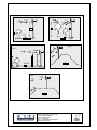
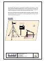
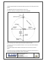
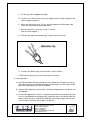
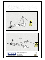
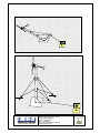
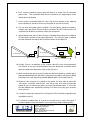
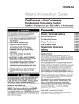
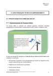
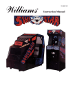
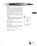
INSTRUCTION MANUAL
INSTALLATION OPERATION AND
MAINTENANCE OF WIND SOLAR
BATTERY HYBRID
POWER PLANTS.
CUSTOMER NAME AND ADDRESS :-
POWER PLANT CONFIGURATION:
LUMINOUS RENEWABLE ENERGY SOLUTIONS PVT. LTD.,
(Formerly: UD Energy Systems Pvt. Ltd.,)
Gat No.1569/B, Vadki Village,
Off Pune –Saswad Road,
Pune – 412308 (India)
Phone: +91 (020) 64011044/65110453-460
www.windsolarzone.com
Index
This manual consists of following sub manuals
Sr.
No
Description
Section
A
1)
Preface
2)
Site Selection (Micrositing) procedure.
3)
Whisper 500 wind turbine installation, operation and maintenance
manual.
B
C
4)
Installation of tower for wind turbine, their erection and cable laying
from turbine to control room and periodic maintenance.
F
5)
Solar photovoltaic structure errection and maintenance procedure.
G
6)
Battery bank errection cabling operation and service manual.
H
7)
Inverter
LUMINOUS RENEWABLE ENERGY SOLUTIONS PVT. LTD.,
(Formerly: UD Energy Systems Pvt. Ltd.,)
Gat No.1569/B, Vadki Village,
Off Pune –Saswad Road,
Pune – 412308 (India)
Phone: +91 (020) 64011044/65110453-460
www.windsolarzone.com
SECTION – A
PREFACE
Wind Solar Hybrid Power Plant
Small battery charging wind turbine generates DC power from wind for charging
batteries. Solar Photovoltaic system also generates DC power from solar Radiation
and charge the batteries. The battery stores energy for the supply of direct DC or
converted AC, through inverter on demand from the user.
Adequate wind speed for power generation is available for 8 to 9 months a year.
Whereas adequate Solar Photovoltaic power supply is also available for 8 to 9 months
a year and is greatly reduced during 3 to 4 months of monsoon due to cloudy weather
but high wind speeds compensates for the loss of solar power.
Disclaimers
The information in this manual is believed to be correct and reliable. However Wind
turbines, electrical power and battery systems, and wind turbine mounting systems are all
capable of causing death or serious injury or fire if incorrectly installed, operated or
maintained and LRES assumes no responsibility whatsoever towards usage of this info by
the user for installation and operation of the system. It is recommended that all activities
are carried out by trained and competent personnel.
All specification is subject to change without notice.
LUMINOUS RENEWABLE ENERGY SOLUTIONS PVT. LTD.,
(Formerly: UD Energy Systems Pvt. Ltd.,)
Gat No.1569/B, Vadki Village,
Off Pune –Saswad Road,
Pune – 412308 (India)
Phone: +91 (020) 64011044/65110453-460
www.windsolarzone.com
SECTION – B
Micrositing Of small wind turbines
Choosing the right type of wind turbine (WIND TURBINE GENERATOR) and its exact
position are very important part. This process is called as micrositing.
During micrositing many aspects have to be considered.
Wind conditions (past & present data concerning wind speed, wind speed average
and preferably wind speed distribution)
Any municipality rules/requirements regarding installation/height requirements(e.g.
distance from building, distance from airports, sensitive areas etc.)
Ownership of the full installation area.
Accessibility to the site.
Influence of the turbine on the environment(e.g. shadow flickering, noise emission) It
is important to keep a distance to next residence in order to not disturb the
inhabitants by noise emission and shadow flickering of the turbine. Normally there
have to be at least 200m between turbine and next residence.
The following points are important for proper siting & good power generation.
Distances between the individual turbines (if multiple turbines are installed) distance
should be atleast 7XD where D is the diameter of the rotor. This ensures that the
wind turbine generator at the front does not block wind flow to the wind turbine
generator behind it. A rotor of WIND TURBINE GENERATOR causes high
turbulence that reduces the energy output of the next turbine. Compared with single
stand alone turbine there are also higher loads on the following turbine because of
the increased turbulence. Therefore the minimum distance between two turbines
depend on the wind conditions and may be 7 rotor diameters (D) in the main wind
direction and 5 diameters in other direction.
To allow smooth flow of air and avoid turbulent flow to the turbine rotor, turbines
should be placed at a distance twice or more times the height of any man made
structure. The turbulent wind flow created by the structure generally extends
vertically to twice the height of the structure, so small structure may not have any
impact on tall turbines. Please see diagram no. A & C.
LUMINOUS RENEWABLE ENERGY SOLUTIONS PVT. LTD.,
(Formerly: UD Energy Systems Pvt. Ltd.,)
Gat No.1569/B, Vadki Village,
Off Pune –Saswad Road,
Pune – 412308 (India)
Phone: +91 (020) 64011044/65110453-460
www.windsolarzone.com
Fig A
Fig B
H
H
2H
H
H
2H
GOOD
Fig D
FIG C
H
H
GOOD
BAD
10H
FIG c
Fig E
GOOD
LUMINOUS RENEWABLE ENERGY SOLUTIONS PVT. LTD.,
(Formerly: UD Energy Systems Pvt. Ltd.,)
Gat No.1569/B, Vadki Village,
Off Pune –Saswad Road,
Pune – 412308 (India)
Phone: +91 (020) 64011044/65110453-460
www.windsolarzone.com
Avoid areas of steep slope. The wind on steep slope tends to be turbulent and has
vertical component that can affect the turbine. Also the construction cost for steep
slope are greatly increased.(pls. see the diagram D)
On the ridgelines and hilltops, set the turbines back from the edge to avoid the
impact of the vertical component of the wind. (pls. see the diagram E)
Preferably select site with flat terrain where there are no significant obstacles around
the proposed location of wind turbine up to a distance of 8L where L=2.25D+/-0.25
and D is the rotor diameter of the wind turbine.
8L
where
L=2.25D,And
D=Diameter of the
Rotor
WIND TURBINE
LOCATION (Centre of the
circle)
LUMINOUS RENEWABLE ENERGY SOLUTIONS PVT. LTD.,
(Formerly: UD Energy Systems Pvt. Ltd.,)
Gat No.1569/B, Vadki Village,
Off Pune –Saswad Road,
Pune – 412308 (India)
Phone: +91 (020) 64011044/65110453-460
www.windsolarzone.com
The knowledge of wind conditions is very important for installation of wind turbine. It is always
best to have measured data of the planned site for a period of at least two years But this is not
always possible for small WTG installation where the cost of measurement may exceed the price
of the WTG system. In case of shorter measurement of period wind consultant can find out the
condition by an interpolation of long term measurement of nearby weather-station.
Based on the information about the wind condition and the exact load it is possible to choose the
type and capacity of turbine which provides the highest energy production while meeting the
external requirements. Based on realistic forecast of the energy production it is possible to decide
whether to invest in wind energy or not.
SITE LAYOUT
CONTROL ROOM
South
Solar array on
PCC
LUMINOUS RENEWABLE ENERGY SOLUTIONS PVT. LTD.,
(Formerly: UD Energy Systems Pvt. Ltd.,)
Gat No.1569/B, Vadki Village,
Off Pune –Saswad Road,
Pune – 412308 (India)
Phone: +91 (020) 64011044/65110453-460
www.windsolarzone.com
Tubular tilt up tower with guy rope support
Tools Required
1) Measuring tape
2) Hammer, drill machine
3) Box spanners
4) Plyer
LRES recommends the tilt up tower for Whisper 500 Whisper 200 and Air x 400 because it is
cost effective and easy to install. Also it can be raised or lowered by a single person with
portable winch for inspection, maintenance, repairs to wind turbine.
The tilt up tower kit includes all the components & fastness required to assemble the tower.
Following is the list of the tower components.
1) Pipe Ø139 OD x 5.5THK x 6000 long- 3 nos.
2) Base plate 12 THK x 460 x 460-1nos
3) Foundation bolt -1” x 12”high tensile half threaded -4 Nos.
4) Gin pole assembly.-1no.
5) Base plate bolt with Nylock nut and washer – M24 x 225 high tensile half threaded -1 no.
6) 5/8” x2” Nylock bolt and washer-16 nos.
7) Turn buckle -8nos.
Turnbuckle
8) ‘D’ Shackle -12nos
‘D’ Shackle
LUMINOUS RENEWABLE ENERGY SOLUTIONS PVT. LTD.,
(Formerly: UD Energy Systems Pvt. Ltd.,)
Gat No.1569/B, Vadki Village,
Off Pune –Saswad Road,
Pune – 412308 (India)
Phone: +91 (020) 64011044/65110453-460
www.windsolarzone.com
9) Guy rope=150mtrs approx.
The tower is guyed in 4 directions each at 90 degree angle to the other.
At every joint of the pipe/flange structure, one set of 4 nos. guy wires are fixed.
refer drawing below.
Where
(1) Pipe Ø139 OD x 5.5 thk x 6000mm long.
(2) Base plate 12 THK x 460 x 460
(3) Nylocknut Washer bolt. M24 x 225 High tensile Half threaded
(4) Nylocknut Washer bolt. 5/8” x 2” High tensile Half threaded
LUMINOUS RENEWABLE ENERGY SOLUTIONS PVT. LTD.,
(Formerly: UD Energy Systems Pvt. Ltd.,)
Gat No.1569/B, Vadki Village,
Off Pune –Saswad Road,
Pune – 412308 (India)
Phone: +91 (020) 64011044/65110453-460
www.windsolarzone.com
Following are the steps to be followed for erection:1. Obtain the drawing for foundation (see the fig below)
LUMINOUS RENEWABLE ENERGY SOLUTIONS PVT. LTD.,
(Formerly: UD Energy Systems Pvt. Ltd.,)
Gat No.1569/B, Vadki Village,
Off Pune –Saswad Road,
Pune – 412308 (India)
Phone: +91 (020) 64011044/65110453-460
www.windsolarzone.com
1. Mark the ground location for the tower base plate, guy anchors & the lifting anchor for the
gin pole.
The appropriate dimension & ground layout are shown in fig:Excavation & marking on site diagram & process to be incorporated.
Make sure that you have sufficient room for the tower & turbine to tilt down.
1. If the site is not in level try to position the tower in such a way so that it will be lowered in
upward direction.
2. Check the diagonal distance between anchor points to ensure that they are correct
square.
3. Screw the guy anchor at 45 degrees pointing towards the tower base stake leaving the 4
inches to 8 inches above the ground as shown in fig (a) below.
LUMINOUS RENEWABLE ENERGY SOLUTIONS PVT. LTD.,
(Formerly: UD Energy Systems Pvt. Ltd.,)
Gat No.1569/B, Vadki Village,
Off Pune –Saswad Road,
Pune – 412308 (India)
Phone: +91 (020) 64011044/65110453-460
www.windsolarzone.com
``
Fig (a)
1. Tower base concrete
We recommend a base that is roughly 600 x 600 mm & 600 mm deep with several pieces of
steel reinforcing bars placed horizontally
2. Cast the hex bolts into the concrete so as to fix the base plate in to the bots.
1. Bolt the base tower section to the base plate using the nuts for tower base.
2. Lay the tower sections (pipes) on the ground connect the tower sections
each other with given hardware.
3. Insert the base of tower (base pipe) in to the base assembly.
LUMINOUS RENEWABLE ENERGY SOLUTIONS PVT. LTD.,
(Formerly: UD Energy Systems Pvt. Ltd.,)
Gat No.1569/B, Vadki Village,
Off Pune –Saswad Road,
Pune – 412308 (India)
Phone: +91 (020) 64011044/65110453-460
www.windsolarzone.com
to
4. Cut the guy ropes of appropriate length.
5. Insert the ‘D’ shackle or eye ring in to the holder part of the tower (diagram & the
anchor support on ground.)
6. Make sure that the guy rings “D” ears are facing towards the base plate & guy
rings ear of anchor are facing towards tower.
7. Slide the guy wires in to the ear ring or ‘D’ shackle.
Please see the diagram ()
8. Slide the wire rope into malleable clips (u clip) on to each wire end.
9. Insert the turn buckle into eye of the anchor using D shackles
10. Roll out the side guy wire to the side anchors turn buckle.
11. Lifting procedure.
a) Start lifting the tower 10 deg to 20 deg at a time. Monitor the side guy wires and gin
pole ropes carefully. they may become either loose or tight if the site and the anchor
points are not perfectly level. See the fig below.
b) Continue lifting adjusting until the tower is 45 deg to 60 deg towards the vertical. See
the fig below.
c) As the tower approaches vertical, it is important to maintain tension on back guy wire
set. this should be done by standing to one side of the anchor, not directly under the
tower. All back guy wires should held, allowing the winch to pull against the tension
until the tower is vertical or the gin pole is on ground.
LUMINOUS RENEWABLE ENERGY SOLUTIONS PVT. LTD.,
(Formerly: UD Energy Systems Pvt. Ltd.,)
Gat No.1569/B, Vadki Village,
Off Pune –Saswad Road,
Pune – 412308 (India)
Phone: +91 (020) 64011044/65110453-460
www.windsolarzone.com
d) Check the side guy wire tension, check the security of the wire rope clips.
e) Maintain tension on lifting cables with winch use a carpenter’s level on base tube to
adjust the guy wire until the base tube is vertical insure that the tower is straight by
sighting up the tower while the final guy adjustment are being made.
Guy rope
LUMINOUS RENEWABLE ENERGY SOLUTIONS PVT. LTD.,
(Formerly: UD Energy Systems Pvt. Ltd.,)
Gat No.1569/B, Vadki Village,
Off Pune –Saswad Road,
Pune – 412308 (India)
Phone: +91 (020) 64011044/65110453-460
www.windsolarzone.com
LUMINOUS RENEWABLE ENERGY SOLUTIONS PVT. LTD.,
(Formerly: UD Energy Systems Pvt. Ltd.,)
Gat No.1569/B, Vadki Village,
Off Pune –Saswad Road,
Pune – 412308 (India)
Phone: +91 (020) 64011044/65110453-460
www.windsolarzone.com
12. Lowering the tower
The procedure is just the reverse of raising although certain precautions must be taken.
Wind Turbine Installation
(a) Assemble wind turbine (refer Whisper 500 Manual) blades not to be fitted with turbine.
(b) Use sling wire for lifting turbine. Sling wire to be fitted carefully so that the weight of
turbine does not come on any weak member. The sling is used to lift turbine by upper
assembly.
Suitable soft material is to be used between sling & turbine to avoid scratches on the turbine.
(c) The freeness of the turbine rotor should be checked by rotation turbine by hand & also
the electromagnetic braking characteristic should be check as per whisper 500 manual.
(d) Lifting of turbine: Turbine should be pulled up by the pulley rope as shown in figure
(below) are should be taken that turbine does not hit any tower structure while being lifting.
For this the turbine is pulled away from tower by separate rope
(e) The temporary pipe fitted to tower for lifting turbine is fitted higher than the tower top to
enable smooth insertion of turbine into the tower top pipe, from the top down wards.
LUMINOUS RENEWABLE ENERGY SOLUTIONS PVT. LTD.,
(Formerly: UD Energy Systems Pvt. Ltd.,)
Gat No.1569/B, Vadki Village,
Off Pune –Saswad Road,
Pune – 412308 (India)
Phone: +91 (020) 64011044/65110453-460
www.windsolarzone.com
(f) ‘Insert ‘tower insert inside the top of pipe, the 6 nos. of insert bolts are used to fix the
‘insert’ of the turbine to tower. Please ref Whisper 500].
(g) Blade assembly
1) Fit the blades on blade plate which is all ready fitted on rotor can of turbine. Blade are to
be fitted wing 2 nos. blade strap provided (please ref of Whisper 500 manual.)
2) The blade are to be fitted in such a way that the concave portion faces the installer & the
convex portion away from installer & the installer is facing wind turbine blade plate. Please
ensure that when the blade is in a vertical position (as shown in diagram below). The leading
edge is on the RHS of installer.
1) For your information thicker edge of blade is leading & thinner is trailing edge. (Fix the
nose cone as described in manual of Whisper 500)
LUMINOUS RENEWABLE ENERGY SOLUTIONS PVT. LTD.,
(Formerly: UD Energy Systems Pvt. Ltd.,)
Gat No.1569/B, Vadki Village,
Off Pune –Saswad Road,
Pune – 412308 (India)
Phone: +91 (020) 64011044/65110453-460
www.windsolarzone.com
SECTION - G
SITING FOR SOLAR PHOTOVOLTAIC ARRAY
Output from SPV array can be improved to the optimum level by taking care of the
following:1. SPV array should be as close to the control room as possible to avoid unnecessary
voltage drop/power loss.
2. A complete SPV array consists of multiple structures with each structure supporting
some SPV panels. All structures SPV output are connected in series or parallel as
required, should be located as close to each other as possible to avoid voltage drop.
For example, A typical installation of 3600W SPV system consists of 4 similar
structures each of 900W (12 nos of 12V 75W SPV module with 4 panels connected
in series and 3 such series strings connected in parallel) as shown in fig. No. A.
Please note that our structure is located as close to other structure as possible
leaving sufficient gap for servicing.
3. While each structure should be close to the next, between structures, adequate
space should be allowed for free movement for servicing.
4. SPV structures should be designed in such a way that all solar panels can be easily
reached by human hand for regular cleaning.
5. In India all the structures with their solar panels fitted on them should be facing
magnetic south. Solar panels should face true south in northern hemisphere and true
north in southern hemisphere. For the purpose of finding the direction, magnetic
compass has to be used. A photograph of a common magnetic compass is given.
LUMINOUS RENEWABLE ENERGY SOLUTIONS PVT. LTD.,
(Formerly: UD Energy Systems Pvt. Ltd.,)
Gat No.1569/B, Vadki Village,
Off Pune –Saswad Road,
Pune – 412308 (India)
Phone: +91 (020) 64011044/65110453-460
www.windsolarzone.com
6. Each structure should be facing south but tilted at an angle from the horizontal
ground level. They should be tilted from the horizontal at a degree equal to the
latitude of the site location.
7. All the structure should be located in such a way that no shadows of any adjoining
trees or building or structures fall on any solar panel at any time of the day.
8. For any wind solar power plant installation, the solar panels should be located in
southern most part of the site and all other installations like WTG, control room, DG
installation etc will be on the northern side of the solar panels.
9. Space between two rows of solar structures should be atleast twice of the height of
the solar panel structures at the highest point of tilt. This minimum space is required
to avoid shadow of one row of solar structure to fall on the row behind it.
True south
H
Solar Array
Solar Array
2H
2H
Fig A
10. Similarly if there is an obstacle, on the southern side of the solar structure/modules
the distance of the solar structure/module facing the obstruction should be atleast
twice the height of the obstruction. Please refer Fig. No. A
11. While installing solar panels on the tin/asbestos roof of any building, sufficient gap is
to be provided between the roof and the solar panels to avoid the solar panels getting
heated by the tin roof. Gaps to be provided between panels for escape of hot air.
12. Whenever solar structure are installed on the ground, the area under & around the
solar panels should be covered with small stone chips and sand to discourage
growth of grass all around solar panels and also to discourage cattle. It also saves
the solar modules from accidentally catching fire if there are any dry grass around it
which can burn.
13. It is best if a water tap is located in the vicinity of the SPV installation to provide water
for periodic cleaning.
14. To avoid the shadow effect of a panel on the total array in which that panel is
included a diode must be connected in reverse polarity to avoid shadowing effect.
LUMINOUS RENEWABLE ENERGY SOLUTIONS PVT. LTD.,
(Formerly: UD Energy Systems Pvt. Ltd.,)
Gat No.1569/B, Vadki Village,
Off Pune –Saswad Road,
Pune – 412308 (India)
Phone: +91 (020) 64011044/65110453-460
www.windsolarzone.com
H
TRUE
SOUTH
J.
B.
PLAIN CONCRETE CEMENT
15. Location of Electrical control room/Battery room
16. Control room should be located as close of the WTG (wind turbine generator) and the
SPV (solar photo voltaic) as possible but not so close as to cast shadow on the SPV.
The control room will house the battery, wind & solar charge controllers and the
inverters.
17. The dimension of the control/battery room should be atleast 12ft X 12ft X 12ft ht. for
upto 10 KW wind solar hybrid system and 12Ft X 20ft X 12ft ht for a 20KW hybrid
system.
18. The control/battery room should be well ventilated for exhausting the small amount of
gas emitted by the battery bank. Preferably it should be open for using natural light
to the extent possible. No other sensitive electronic equipment should be located in
the same room as the battery to avoid corrosion (This includes the master controller
if supplied along with wind solar diesel hybrid system. The master controller should
be located in room/space outside the battery room but has to be very close to the
battery bank)
19. The control/battery room should be easily accessible for servicing.
LUMINOUS RENEWABLE ENERGY SOLUTIONS PVT. LTD.,
(Formerly: UD Energy Systems Pvt. Ltd.,)
Gat No.1569/B, Vadki Village,
Off Pune –Saswad Road,
Pune – 412308 (India)
Phone: +91 (020) 64011044/65110453-460
www.windsolarzone.com
Trouble shooting
The solar panels don’t have any mechanical parts involved in it so there is no
mechanical trouble shooting involved in it.
Also most of the time the solar photovoltaic panels mounting structure is fixed type and
no tracking system is involved in it hence troubleshooting for the solar structure is not
there.
Troubleshooting symptoms
Symptoms
Possible cause
1) Solar panels not giving 1) Dusty panels
the desired power even
on bright sunny days.
2) Loose connection at panel
terminals
Correction
1) Clean the panels at least
once in three days.
2) Tight all the loose
connections found at solar
solar panels
3) Loose connection at the
controller terminals
3) Tight all the loose
connections found at solar
charge controller.
4) Loose connection at the battery
terminal
4) Tight all the loose
connections found at battery
terminals
5) Batteries are fully charged or
sulphated.
5) Let the battery discharge
or consult the battery manual
from the battery
manufacturer.
6) Cut in solar cables
LUMINOUS RENEWABLE ENERGY SOLUTIONS PVT. LTD.,
(Formerly: UD Energy Systems Pvt. Ltd.,)
Gat No.1569/B, Vadki Village,
Off Pune –Saswad Road,
Pune – 412308 (India)
Phone: +91 (020) 64011044/65110453-460
www.windsolarzone.com
BATTERY
INDEX
1)
Description of Battery Bank (Tubular & VRLA)
2)
Battery room and battery stand layout
3)
Receiving, Inspection & storage of battery at site.
4)
Erection and interconnection of battery bank
5)
Initial charging/first charge of battery/commissioning of battery
bank.
6)
Preventative maintenance procedure
LUMINOUS RENEWABLE ENERGY SOLUTIONS PVT. LTD.,
(Formerly: UD Energy Systems Pvt. Ltd.,)
Gat No.1569/B, Vadki Village,
Off Pune –Saswad Road,
Pune – 412308 (India)
Phone: +91 (020) 64011044/65110453-460
www.windsolarzone.com
1) DESCRIPTION OF BATTERY BANK (TUBULAR & VRLA)
A secondary electric storage cell stores electrical energy in the form chemical energy when it
is charged and delivers electrical energy by commissioning chemical energy when it is
discharged.
Lead Acid Battery
A lead acid electronic storage cell consists of a set of positive plates/anode (containing lead
dioxide) and negative plates/cathode (containing pure spongy lead) immersed in an
electrolyte which is dilute sulphuric acid. Non conducting but permeable separators are
used in between positive and negative plates to avoid short circuit.
All these components are housed in a hard rubber or plastics container which is known as
the cell box/container. All positive plates are connected in parallel to the outside positive
terminal and all negative plates connected in parallel to a negative terminal. Direct current
electricity can be delivered to and taken out from the cell through this terminals.
A lead acid cell has an open circuit voltage of 2V. When multiple cells are connected in
series the voltage of all cells are added (say 12 cells connected in series will provide a total
of 24V) and all these cells together is known as a battery bank or more commonly “Battery”
TUBULAR BATTERY
A tubular battery consists of positive plates which are made of tubes holding lead dioxide –
all tubes joined together. The positive plate is a flat pasted plate. It has a flooded electrolyte
design where electrolyte in liquid from is stored in the battery cell box. The water in the
electrolyte needs replenishment on periodic basis between once in 9 months to a year,
depending on the design of the battery. The tubular battery is the steadiest among all lead
acid batteries for heavy cycling or deep discharge and recharge operators.
Under repeated 80% depth of discharge these batteries survive at least 1200 cycles of
charge and discharge. The life cycle can be increased to 2500 cycles if depth of discharge
is reduced to 50% and 5000 cycles if it is reduced to 20% of battery capacity. Generally in
solar photovoltaic and wind solar hybrid power plant applications these type of batteries are
almost always used and provide a life of around 8-10 years for large battery banks if used
and maintained properly.
LUMINOUS RENEWABLE ENERGY SOLUTIONS PVT. LTD.,
(Formerly: UD Energy Systems Pvt. Ltd.,)
Gat No.1569/B, Vadki Village,
Off Pune –Saswad Road,
Pune – 412308 (India)
Phone: +91 (020) 64011044/65110453-460
www.windsolarzone.com
VRLA BATTERY
Valve regulated lead acid (VRLA) batteries consists of plate pasted positive and negative
plates with a glasswool absorbent mat separator in between them. The glasswool mat is
partially soaked with electrolyte and there is no free/flooded electrolyte in the battery.
That is why it is also known as an AGM (absorbent glass mat battery). These are housed in
a plastic container over sealed from atmosphere but with a relief valve which allows gas to
escape if high pressure is developed inside the battery.
Due to the design, the oxygen gas evolving from the battery is recombined and re-forms
back into water and no water is lost from battery due to which it does not require any water
replenishment.
VRLA is ideally suited for floating or shallow discharge operations. At 80% depth of
discharge the cycle life if normally not more than 500 cycles. It also cannot be charged at
high voltages and its life is severely affected if exposed to higher temperatures above 350C.
In recent times a modified version of VRLA known as tubular gel battery (the AGM
technology is replaced by gel technology) has hit the market. It is supposed to have a cycle
life as good as the flooded tubular battery but it suffers from the same problems when
charged at higher voltages. Another major problem of AGM/Gel batteries is the extremely
difficult/impossible process of reviving battery if kept in discharged condition for a long time.
In this manual where batteries will be exclusively used for wind solar hybrid and solar power
plants, we have delt with tubular batteries and operational maintenance aspect only and not
for any VRLA battery.
II) BATTERY ROOM AND LAYOUT
Battery Room
A battery room should have sufficient space for installing the battery stands and also for
movement of personnel for servicing the batteries. For this purpose, a proper battery
installation layout drawing should be prepared first and then the battery room design should
be finalized considering the battery installation layout. Sufficient gap should be provided
between the wall of the battery room and the adjoining row of batteries to avoid electrical
earth leakage. Refer sample drawings attached.
LUMINOUS RENEWABLE ENERGY SOLUTIONS PVT. LTD.,
(Formerly: UD Energy Systems Pvt. Ltd.,)
Gat No.1569/B, Vadki Village,
Off Pune –Saswad Road,
Pune – 412308 (India)
Phone: +91 (020) 64011044/65110453-460
www.windsolarzone.com
The floor of the battery room should be preferably acid resistant and no inflammable
materials are to be used inside the battery room. The room should be well ventilated either
by two open windows or by using suitable exhaust fan to enable continuous change of air
inside the room.
A sink with a water tap is to be preferably located inside the battery room to enable washing
away of acid spillage if it happens accidentally. No sensitive electronic equipment is to be
located inside the battery room. It is better to avoid harsh direct sunlight to come inside the
battery room.
Battery Stand
Battery stands are ideally made from good quality wood, coated with atleast two layer of anti
sulphuric paint. Alternatively mild steel battery stands can also be used if suitably coated
with rubber/rubberized paint/good quality and thickness of epoxy.
It is preferable to use porcelain or hard plastics insulators between the battery stand and the
floor to avoid earth leakage. While it is preferable for batteries up to 48V, it is an absolute
must for high voltage batteries like 96V, 120V, 240 and above.
LUMINOUS RENEWABLE ENERGY SOLUTIONS PVT. LTD.,
(Formerly: UD Energy Systems Pvt. Ltd.,)
Gat No.1569/B, Vadki Village,
Off Pune –Saswad Road,
Pune – 412308 (India)
Phone: +91 (020) 64011044/65110453-460
www.windsolarzone.com
The battery stand is to be assembled and installed exactly as per the battery installation
layout drawing provided for the particular site.
BATTER
BATTER
UPPER TIER
BATTER
BATTER
LOWER TIER
DOUBLE ROW DOUBLE TIER LAYOUT (Front View)
LUMINOUS RENEWABLE ENERGY SOLUTIONS PVT. LTD.,
(Formerly: UD Energy Systems Pvt. Ltd.,)
Gat No.1569/B, Vadki Village,
Off Pune –Saswad Road,
Pune – 412308 (India)
Phone: +91 (020) 64011044/65110453-460
www.windsolarzone.com
48VDC
=
+
-
-
LOWER TIER SECOND ROW
+
UPPER TIER SECOND ROW
UPPER TIER FIRST ROW
LOWER TIER FIRSTROW
-
+
-
48V (24NOS X 2CELLS) BATTERY CONNECTION DIAGRAM (Top View)
LUMINOUS RENEWABLE ENERGY SOLUTIONS PVT. LTD.,
(Formerly: UD Energy Systems Pvt. Ltd.,)
Gat No.1569/B, Vadki Village,
Off Pune –Saswad Road,
Pune – 412308 (India)
Phone: +91 (020) 64011044/65110453-460
www.windsolarzone.com
+
(III) RECEIVING, INSPECITON AND STORAGE OF BATTERY AT SITE.
Battery received in dry and in charged condition:
(1) Open out packing cases and check individual battery cells for any physical damage.
(2) Check the no. of battery cells received as per packing list/Challan/Invoice. Check name
plate of each cell for its capacity.
(3) Electrolyte and battery grade water is normally supplied alongwith a dry uncharged
battery cells. The manufacturer indicates the quantity of electrolyte required per cell from
which total electrolyte quantity/volume can be collected.
Check whether adequate
electrolyte has been received.
(4) The manufacturer indicates the fill in electrolyte specific gravity. Normally this is between
1.200 to 1.230 specific gravity @ 270C. Check specific gravity and temperature of electrolyte
delivered.
(5) Battery grade water is required for final adjustment of specific gravity of the cells. Order
for & receive adequate water equivalent to 10% of the required volume of electrolyte.
(6) If the battery is not installed immediately, store the battery cells in cool and dry place and
avoid direct sunlight. The electrolyte and water should be stored away from any sensitive
electrical or electronic equipment.
Battery received in charged condition:
Some manufacturers supply batteries or cells in fully charged condition.
(1) Inspect each battery cell for any physical damage.
(2) Check electrolyte level in each cell and top up electrolyte of same specific gravity if the
level is found low.
(3) Check specific gravity of electrolyte of all cells. If it matches with the value given by the
manufacturer for specific gravity in fully charged condition, the battery is deemed to have
been received in fully charged condition.
In case, the specific gravity is lower than recommended, the battery will require a charge to
increase the specific gravity to required level and fully charge the batteries.
(4) Check the voltages of each individual cell and it should be between 2V and 2.1V per cell.
If the voltage of any cell is less than 2V, it is possible that there is a defect in that cell.
(5) If not installed immediately, store the batteries/cells in a cool and dry place.
LUMINOUS RENEWABLE ENERGY SOLUTIONS PVT. LTD.,
(Formerly: UD Energy Systems Pvt. Ltd.,)
Gat No.1569/B, Vadki Village,
Off Pune –Saswad Road,
Pune – 412308 (India)
Phone: +91 (020) 64011044/65110453-460
www.windsolarzone.com
(IV) ERECTION AND IN TERCONNECITON OF BATTERY BANK
(1) Install the batteries/cells on the battery stand as per battery stand/battery erection
drawing attached. In a row, the cells are to be postponed in such a way that positive
terminal of one cell faces the negative terminal of the next cell and so on to enable
connection in series.
(2) Ensure that each row of cells on the stand are positioned in an absolute straight line by
matching the edge of all the cells in a row in a single line. A piece of string can be used for
aligning all cells in a row in a straight line. There should be a small gap of about 10/20 mm
between each cell in a row.
(3) Check polarity of each cell by a center zero voltmeter or any voltmeter and ascertain that
when the positive of the voltmeter is connected to the positive terminal and negative of
voltmeter is connected to negative terminal of battery, the deflection from needle should be
the same direction for all cells in series.
(4) Connect all cells in a row in series connection by connecting the positive terminal of one
cell to the negative terminal of the next cell. Repeat this for all other cells.
(5) For intercell connection, use cables of adequate core size/cross section supplied
alongwith the battery. The interconnecting cables of suitable length are supplied with the
battery with both ends duly provided with cable lugs for fixing to the terminals with nuts and
bolts. If there are two positive terminals and two negative terminals of each cell, use two
cables for series connection from one cell to the next. One cable to be connected to each
set of positive and negative terminals of the adjoining cell.
(6) Before fixing the intercell cable connectors with nuts and bolts to the terminals, smear
petroleum jelly on the nuts and bolts and also on the terminals before tightening the
fasteners.
(7) If the battery bank is installed in a double row double tier configuration, the top two rows
in the top tier should be connected in series and two rows in the bottom should be connected
in another series.
Then the top tier and the bottom tier should be connected in series so that the positive
terminal of the battery bank is available at the starting of upper tier and negative terminal of
the battery bank is at the end of lower tier.
In case two battery banks are to be connected in parallel for doubling the capacity, the top
tier and the bottom tier will be connected in parallel that is positive end of top tier will be
connected to the positive end of bottom tier which is just below it and same shall be done for
the negative terminal parallel. Here the positive terminal of the battery will be at one end of
the top tier and the negative terminal will be at the other end of the top tier. Please refer
attached figure.
(8) After connection, ensure that the vent plugs and electrolyte level indicator are normally
fixed in place on each cell.
(9) Check the normal battery bank voltage.
LUMINOUS RENEWABLE ENERGY SOLUTIONS PVT. LTD.,
(Formerly: UD Energy Systems Pvt. Ltd.,)
Gat No.1569/B, Vadki Village,
Off Pune –Saswad Road,
Pune – 412308 (India)
Phone: +91 (020) 64011044/65110453-460
www.windsolarzone.com
(V) INITIAL CHARGING/FIRST CHARGE OF BATTERY/COMMISSIONING OF
BATTERY BANK:
This is done for battery/cells received in dry and uncharged condition.
(1) Fill the cells with dilute sulphuric acid supply alongwith the battery.
(2) Allow between 12-24 hours rest period for soaking acid in the plates and for cooling down
to room temperature approximately. Shorter time can allowed in winter when the cooling is
fast. Further more than 24 hours should not be allowed.
(3) Start charging with constant current at the finishing rate as given fin the chart here
under:(4) Obtain hourly specific gravity temperature and voltage readings of all cells as per sample
sheet attached.
(5) Continue charging till the battery is fully charged. Full charge set can be ascertained by
ensuring the following parameters.
(a) Cell voltages remain constant for three consecutive hourly readings.
(b) Cells specific gravity readings remain constant for three consecutive hourly readings.
(c) Free gassing is observed in all the cells.
(d) Total cumulative amphere hour charge delivered to the battery is atleast 4-5 times of the
amphere hour capacity of the battery.
(6) Once the battery is fully charged, most of the cells will show specific gravity more than
that specified for full charge battery by the manufacturer. Normally it is recommended
specific gravity at full charge is 1.250. However, many cells will have specific gravity above
1.250.
The specific gravity of all cells are to be adjusted to 1.250 by taking out some electrolyte
from the cell and adding some battery grade water. While continuing the initial charging to
allow the electrolyte and water to mix properly. While adding water, fill to the topmost level
allowed. This will make up for the evaporation loss and electrolysis loss of water during
charging.
(7) Fix vent plugs and electrolyte level to indicators firmly on each cell.
(8) Clean all the cells especially the top portion with water and cloth so that all traces of acid
is removed from the external part of the cells.
(9) If adequate time is available it is always better to discharge battery bank at C10 rate (see
the battery specs chart) to 100% discharge level and charging back fully. This increases the
battery effective capacity.
(10) The battery bank is now ready for connecting to the load/commissioning.
LUMINOUS RENEWABLE ENERGY SOLUTIONS PVT. LTD.,
(Formerly: UD Energy Systems Pvt. Ltd.,)
Gat No.1569/B, Vadki Village,
Off Pune –Saswad Road,
Pune – 412308 (India)
Phone: +91 (020) 64011044/65110453-460
www.windsolarzone.com
(VI) PREVENTATIVE MAINTENANCE PROCEDURE
(1) Clean the battery cells and keep the cells tops in clean and dry conditions – once in six
months.
(2) Top up the battery cells with battery grade water up to the required level given once in 69 months. Please watch the cell electrolyte indicator and top up level indicator reaches its
lowest level. From this you will get an indication regarding the frequency of topping up.
(3) Clean the battery terminals with cloth/wire brush soaked in water and re-apply petroleum
jelly – once in a year. In corrosive atmosphere like near the sea side, the frequency may be
more.
(4) Check all inter cell, inter row and inter tier cable connectors for the tightness of
connection and tighten if found loose.
(5) Check battery stand for any sign of sulfation or corrosion and clean with cloth and water.
(6) Check voltage and specific gravity of each cell once in a month and record in the battery.
EQUALISING CHARGE FOR CYCLING BATTERIES
(1) Tubular flooded battery cell regularly cycled (charged & discharged deeply) - few cells
fall out of step for a period of time.
(2) After a period some cells have high voltage and high specific gravity and some cells are
not fully charged and have low specific gravity and voltage.
(3) The cells which have low state of charge have a sharp voltage increase on constant
current charge due to which the charger is automatically switched OFF even if your battery is
not fully charged.
(4) To avoid this, equalizing charge is to be imparted to battery on a periodic basis say
between once in 45 days to 60 days.
(5) The proposal l involves charging the full battery but at low approximately constant current
of not more than 5% of battery capacity in amps. This means, for a battery of 1200 Ah max
equalizing charge current will be 60 amps.
(6) Equalizing charging at above rate is to be continued till all cells show full charge voltage
of 2.65 to 2.75/48V battery shows 66V and all the cells specific gravity become equal at
around 1.250 for each cell.
(7) Equalizing charge increased the efficiency and life of battery and should be imparted
once in 45-60 days during the entire life time of battery.
LUMINOUS RENEWABLE ENERGY SOLUTIONS PVT. LTD.,
(Formerly: UD Energy Systems Pvt. Ltd.,)
Gat No.1569/B, Vadki Village,
Off Pune –Saswad Road,
Pune – 412308 (India)
Phone: +91 (020) 64011044/65110453-460
www.windsolarzone.com