1
DIGITAL CAMERA
FinePix S6000fd/
S6500fd
SERVICE MANUAL
US/EU/EG/EE/AS/CH/JP-Model
CAUTION
BECAUSE THIS PRODUCTIS RoHS LEAD-FREE COMPLIANT, USE THE DESIGNATED AFTER-SELES PARTS AND THE DESIGNATED LEAD-FREE SOLDER WHEN
PERFORMING REPAIRS. (Refer to page 3 to page 5)
WARNING
THE COMPONENTS IDENTIFIED WITH THE MARK “
” ON THE SCHEMATIC
DIAGRAM AND IN THE PARTS LIST ARE CRITICAL FOR SAFETY.
PLEASE REPLACE ONLY WITH THE COMPONENTS SPECIFIED ON THE SCHEMATIC
DIAGRAM AND IN THE PARTS LIST.
IF YOU USE PARTS NOT SPECIFIED, IT MAY RESULT IN A FIRE AND AN
ELECTRICAL SHOCK.
FUJI PHOTO FILM CO., LTD.
Ref.No.:ZM00647-100
Printed in Japan 2006.09
FinePix S6000fd/S6500fd Service Manual
SAFETY CHECK-OUT
After correcting the original problem, perform the following
safety check before return the product to the customer.
1. Check the area of your repair for unsoldered or poorly
soldered connections. Check the entire board surface
for solder splasher and bridges.
7.
CAUTION: FOR CONTINUED
PROTECTION AGAINST FIRE
HAZARD, REPLACE ONLY WITH
SAME TYPE 2.5 AMPERES 125V
FUSE.
2. Check the interboard wiring to ensure that no wires are
“pinched” or contact high-wattage resistors.
2.5A 125V
3. Look for unauthorized replacement parts, particularly
transistors, that were installed during a previous repair.
Point them out to the customer and recommend their
replacement.
4. Look for parts which, though functioning, show obvious
signs of deterioration. Point them out to the customer
and recommend their replacement.
2.5A 125V
RISK OF FIREREPLACE FUSE
AS MARKED
8.
WARNING:
TO REDUCE THE ELECTRIC
SHOCK, BE CAREFUL TO
TOUCH THE PARTS.
5. Check the B + voltage to see it is at the values
specified.
WARNING!
6. Make leakage - current measurements to determine
that exposed parts are acceptably insulated from the
supply circuit before returning the product to the
customer.
2
ATTENTION: AFIN D'ASSURER
UNE PROTECTION
PERMANENTE CONTRE LES
RISQUES D'INCENDIE,
REMPLACER UNIQUEMENT
PAR UN FUSIBLE DE MEME,
TYPE 2.5 AMPERES, 125 VOLTS.
HIGH VOLTAGE
FinePix S6000fd/S6500fd Service Manual
RoHS lead-free compliance
Because this product is RoHS lead-free compliant, use the designated after-sales parts and the designated lead-free solder
when performing repairs.
<Background & Overview>
With the exception of parts and materials expressly excluded from the RoHS directive (*1), all the internal connections and
component parts and materials used in this product are lead-free compliant (*2) under the European RoHS directive.
*1: Excluded items (list of the main lead-related items)
• Lead included in glass used in fluorescent tubes, electronic components and cathode-ray tubes
• Lead in high-melting-point solder (i.e. tin-lead solder alloys that contain 85% lead or more)
• Lead in ceramic electronic parts (piezo-electronic devices)
• Mercury contained in fluorescent tubes is also excluded.
*2: Definition of lead-free
A lead content ratio of 0.1 wt% or less in the applicable locations (solder, terminals, electronic components, etc.)
<Reference>
RoHS:
The name of a directive issued by the European Parliament aimed at restricting the use of
certain designated hazardous substances included in electrical and electronic equipment.
Designated substances (6): Lead, mercury, cadmium, hexavalent chromium, polybrominated biphenyls (PBBs) and
polybrominated diphenyl ether (PBDE)
<Lead-free soldering>
When carrying out repairs, use a designated lead-free solder, bearing in mind the differing work practices for conventional
solder (eutectic) and lead-free solder.
Differences in the soldering work for lead-free and eutectic solder
When the soldering work practices for eutectic solder and lead-free solder are compared, the main differences are as shown
below. In particular, when lead-free solder is used, the solder tends to be less workable than when eutectic solder is used.
Accordingly, the soldering techniques used must take that into account.
1
Difference
The solder starts melting later.
2
Poor wetting
3
Solder feed rate is difficult to control.
4
6
Wetting the insides of through holes is especially
difficult.
During repairs (or modifications) removing solder
from inside through holes is difficult.
There is serious carbonization of the soldering iron.
7
The surface is not glossy.
5
Countermeasure
The initial melting point of lead-free solder is high, so you
have to get used to it.
Move the tip of the soldering iron around to heat the entire
connection to the melting temperature and assist wetting.
Use the solder (wire) diameter and soldering iron that are
best suited to connection being soldered.
First apply solder to the area immediately around the
through hold and then feed the solder into the hole.
Use a suitable wicking wire (with a suitable method and
heating) and a suction tool.
Either put solder onto the soldering iron tip after completing
the work, or turn the iron off frequently.
Learn to recognize the appearance of the surface.
3
FinePix S6000fd/S6500fd Service Manual
Setting temperature during lead-free soldering
• Lead-free solder melting temperature
The melting point of eutectic (Sn-Pb) solder is 183°C, while the melting point of lead-free solder (Sn-Ag-Cu) is 30°C higher
at 220°C.
• Soldering iron tip temperature
The temperature setting for the soldering iron used should be such that the tip of the soldering iron is at the correct
bonding temperature for the connection. This temperature is normally set at around 100°C higher than the melting point of
the solder.
However, the actual temperature should take into account the shape and size of the soldering iron tip, the heat tolerance
of the connection and the workability of that temperature.
• Correct bonding temperature
The correct bonding temperature refers not to the temperature of the heat source, but to the bonding temperature that will
give the best bond strength.
Precautions when soldering with lead-free solder
• Soldering iron maintenance
Because of the high soldering iron temperature in lead-free soldering, there is rapid carbonization of the flux adhering to
the tip of the soldering iron.
(1) Always cover the tip of the soldering iron with solder when it is not being used.
(2) If the tip is black from carbonization, wipe it gently with a paper towel soaked in alcohol until the solder will wet.
• Uniform heating of the board and components
To ensure that the lead-free solder wets the entire surface of the pattern and the lands despite its poor wetting
characteristics, you must move the tip of the soldering iron over a wide area to raise the temperature of the entire
connection.
Soldering iron
A soldering iron with a temperature control is best.
4
FinePix S6000fd/S6500fd Service Manual
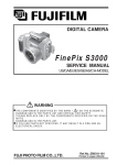
Solder wire (thread)
Use the lead-free solders specified below.
Solder type: Sn96.5Ag3Cu0.5 (Displayed symbol: SnAgCu)
Wire diameter: 0.6, 0.8 or 1.0 mm
Sample:
lead-free
Wire diameter 0.8mm
Solder type (Displayed symbol)
SnAgCu
Flux
Conventional flux can be used.
Solder application wires (mesh, wicking wire, etc.)
Conventional application wires can be used.
5
CONTENTS
FinePix S6000fd/S6500fd Service Manual
CONTENTS
1. General ........................................................ 1-1
1-1. Product specification .......................................... 1-1
1-2. Explanation of Terms .......................................... 1-4
1-3. Names of External Components ........................ 1-5
2. Disassembly ................................................ 2-1
2-1.
2-2.
2-3.
2-4.
Names of internal Components .......................... 2-1
Removing the REAR CONST ............................. 2-2
Disassembling the REAR CONST ..................... 2-4
Removing the MAIN PWB ASSY and
FLASH PWB ASSY ............................................ 2-5
2-5. Removing the HOLDER BATTERY .................... 2-7
2-6. Removing the LENS ASSY ................................ 2-8
2-7. Removing the LENS HOLDER ........................... 2-9
2-8. Removing the FLASH CONST .......................... 2-11
2-9. Removing the FRONT CONST ......................... 2-11
2-10. Specifications for the sheet component
attachment locations ........................................ 2-12
2-10-1. Affixing the REINFORCEMENT LCD ... 2-12
2-10-2. Affixing the MF SHEET ........................ 2-13
2-10-3. Affixing the FLASH PWB GASKET ...... 2-13
3. Schematics .................................................. 3-1
3-1. Cautions .............................................................
3-2. Basic Block Names and Functions .....................
3-3. Description of Main Block Functions ..................
3-3-1. Technical Overview ................................
3-4. Block Diagram ....................................................
3-5. Overall connection Diagram ...............................
6
3-1
3-1
3-2
3-2
3-3
3-4
3-6. Circuit Diagrams ................................................. 3-5
3-6-1. AV BLOCK ............................................. 3-5
3-6-2. CAMERA BLOCK .................................. 3-6
3-6-3. DCDC BLOCK ....................................... 3-7
3-6-4. EVF BLOCK ........................................... 3-8
3-6-5. FDI BLOCK ............................................ 3-9
3-6-6. FLASH JACK BLOCK .......................... 3-10
3-6-7. KEY BLOCK .......................................... 3-11
3-6-8. KSW BLOCK ....................................... 3-12
3-6-9. LCD BLOCK ........................................ 3-13
3-6-10. MOTOR BLOCK .................................. 3-14
3-6-11. PMAN BLOCK ..................................... 3-15
3-6-12. PROCESS BLOCK (IO) ....................... 3-16
3-6-.13 PROCESS BLOCK (PW) ..................... 3-17
3-6-14. PROCESS BLOCK (SYS) ................... 3-18
3-6-15. AF LED BLOCK ................................... 3-19
3-6-16. CCD FPC BLOCK ................................ 3-19
3-6-17. CN BLOCK .......................................... 3-20
3-6-18. FSW BLOCK ........................................ 3-20
3-6-19. EMI BLOCK ......................................... 3-21
3-6-20. LCD DATA 7 BLOCK ............................ 3-22
3-6-21. MEDIA BLOCK .................................... 3-23
3-6-22. MSW BLOCK ....................................... 3-23
3-6-23. PLUNGER BLOCK .............................. 3-24
3-6-24. USB BLOCK ........................................ 3-24
3-6-25. RSW BLOCK ....................................... 3-25
3-6-26. XE BLOCK ........................................... 3-25
3-6-27. SSW BLOCK ....................................... 3-26
3-7. Mounted Parts Diagrams .................................. 3-27
3-7-1. FSW PWB ASSY ................................. 3-27
3-7-2. KSW PWB ASSY ................................ 3-28
3-7-3. MSW PWB ASSY ............................... 3-29
3-7-4. RSW PWB ASSY ................................ 3-30
3-7-5. SSW PWB ASSY ................................ 3-31
3-7-6. XE PWB ASSY ................................... 3-32
3-7-7. FLASH PWB ASSY .............................. 3-33
3-7-8. MAIN PWB ASSY ................................ 3-34
CONTENTS
FinePix S6000fd/S6500fd Service Manual
CONTENTS
4. Adjustments ................................................. 4-1
6. Parts List ...................................................... 6-1
4-1. Important point before Adjustment ..................... 4-1
4-1-1. The handling of image files in internal
memory .................................................. 4-1
4-1-2. Important point Adjustment when
Replacing Major Parts ............................ 4-2
4-2. Measuring Instruments Used ............................. 4-2
4-3. Use Jig list .......................................................... 4-3
4-4. Calibration method of pattern box ...................... 4-3
4-5. Adjustment software installation ......................... 4-4
4-5-1. Various downloading software
decompressions, preservation methods,
and notes ............................................... 4-4
4-5-2. Installation of DSC jig driver ................... 4-5
4-5-3. Adjustment software initiation method ... 4-5
4-6. Initial Settings of the Adjustment Software ......... 4-6
4-7. Starting the Adjustment Software ....................... 4-9
4-8. [R] : Flash Memory Reset ................................. 4-12
4-9. [F4] : CCD Defect Correction /
OFD Adjustment ............................................... 4-14
4-10. [F5] : Camera Adjustment ................................. 4-18
4-11. [ S ]: Shading compensation adjustment .......... 4-24
4-12. [F6] : AF Adjustment ......................................... 4-29
4-13. [F7] : Flash Adjustment ..................................... 4-32
4-14. [F1] : Battery Voltage Adjustment ..................... 4-34
4-15. [F2] : Mode Dial Adjustment ............................. 4-38
4-16. [F11] : Video Adjustment .................................. 4-40
4-17. [F3] : LCD Adjustment ...................................... 4-42
4-18. [F8] : Firmware Download ................................ 4-44
4-19. [F12] : End Setting ............................................ 4-46
6-1. Packing and Accessories ................................... 6-1
6-1-1. US-model ............................................... 6-1
6-1-2. JP-model ................................................ 6-2
6-1-3. EU-model ............................................... 6-3
6-1-4. EG-model ............................................... 6-4
6-1-5. EE-model ............................................... 6-5
6-1-6. EE-model (JP Production) ..................... 6-6
6-1-7. AS-model ............................................... 6-7
6-1-8. CH-model ............................................... 6-8
6-2. Cabi Front Block ................................................. 6-9
6-2-1. US/JP-model .......................................... 6-9
6-2-2. EU/EG/EE-model ..................................... 10
6-2-3. EE-model (JP Production) .................... 6-11
6-2-4. AS-model ............................................. 6-12
6-2-5. CH-model ............................................. 6-13
6-3. Cabi Rear Block ............................................... 6-14
6-3-1. US/EU/EG/EE/AS/CH-model ............... 6-14
6-3-2. JP-mode .............................................. 6-15
6-4. Electrical parts .................................................. 6-17
7. Appendix ...................................................... 7-1
7-1. List of Related Technical Updates Issued .......... 7-1
5. Inspection .................................................... 5-1
5-1. Required Measuring Equipment ......................... 5-1
5-2. Connection of Measuring Equipment ................. 5-1
5-3. Inspection and Factory Settings ......................... 5-2
7
FinePix S6000fd/S6500fd Service Manual
MEMO
8
1. General
FinePix S6000fd/S6500fd Service Manual
1. General
1-1.
Product specification
System
Model
Digital camera FinePix S6000fd / FinePix S6500fd
Effective pixels
6.3 million pixels
CCD
1/1.7-inch Super CCD HR
Storage media
Internal memory (approx. 10 MB)/xD-Picture Card (16/32/64/128/256/512 MB/1 GB/2 GB)
File format
Still image: DCF-compliant
Compressed: Exif ver.2.2 JPEG, DPOF-compatible
Uncompressed: CCD-RAW (RAF)
*Design rule for Camera File System compliant DPOF compatible
Movie: AVI format, Motion JPEG
Audio: WAVE format, Monaural sound
Number of recorded pixels
Still image:2848 × 2136 pixels/3024 × 2016 pixels/2048 × 1536 pixels/
Lens
Fujinon 10.7× optical zoom lens
Focal length
f=6.2 mm-66.7 mm
Digital zoom
Approx. 2.0× (10.7× optical zoom lens is used together: Max. zoom scale: approx. 21.4×)
Aperture (Wide-angle)
F2.8 to F11 Up to 13 steps in 1/3 EV increments Manual/Auto selectable
Focal range
Normal:
1600 × 1200 pixels/640 × 480 pixels (
/
/
/
/
)
F2.8-F4.9
(Equivalent to approx. 28 mm-300 mm on a 35 mm camera)
Wide-angle: approx. 40 cm (1.3 ft.) to infinity (In High-speed shooting mode:
approx. 2.0 m (6.6 ft.) to infinity)
Telephoto: approx. 2.0 m (6.6 ft.) to infinity (In High-speed shooting mode:
approx. 4.0 m (13.1 ft.) to infinity)
Macro:
Wide-angle: approx. 10 cm (3.9 in.) to 3.0 m (9.8 ft.)
Telephoto: approx. 90 cm (3.0 ft.) to 3.0 m (9.8 ft.)
Super macro: approx. 1 cm to 1.0 m (0.4 in. to 3.3 ft.) (Wide-angle only)
Sensitivity
AUTO/Equivalent to ISO 100/200/400/800/1600/3200
Photometry
TTL 256-zones metering Multi, Spot, Average
Exposure control
Program AE (When using P mode : Program Shift is enabled)/Shutter priority AE/
Aperture priority AE/Manual exposure
Scene position
(NATURAL LIGHT),
(SPORT),
(NIGHT),
(MUSEUM),
Picture Stabilization
(NATURAL & ),
(PORTRAIT),
(FIREWORKS),
(SUNSET),
(PARTY),
(FLOWER),
(LANDSCAPE),
(SNOW),
(BEACH),
(TEXT)
Available
Intelligent Face Detection Available
Exposure compensation
Shutter speed
-2 EV to +2 EV in 1/3 EV-step increments (P, S, A)
,
,
,
,
,
,
,
,
,
,
,
,
: 1/4 sec. to 1/4000 sec*.
: 4 sec. to 1/500 sec.*
: 4 sec. to 1/2 sec.*
: 1/45 sec. to 1/1000 sec.* (flash only).
P, S, A: 4 sec. to 1/4000 sec.*
M: 30 sec. to 1/4000 sec.* *depend on Exposure mode
Continuous shooting
Top-3:
Number of recorded frames: up to 3 frames (Max. 2.2 frames/sec.)
Final-3:
Number of recorded frames:
Last 3 frames before releasing the shutter button (Max. 2.2 frames/sec.)
Long-period: Number of recorded frames: Depend on memory size. 1.5 sec.
interval at
Auto bracketing
N depending on quality level. (Max. 0.6 frames/sec.)
± 1/3 EV, ± 2/3 EV, ± 1 EV
1-1
1. General
FinePix S6000fd/S6500fd Service Manual
System
Focus
Mode: Single-AF, Continuous AF, Manual focus/One-touch AF (when using Manual focus)
AF system: TTL contrast-type, AF-assist illuminator
AF frame selection: AF (CENTER), AF (MULTI), AF(AREA)
White balance
Automatic scene recognition/Preset (Fine, Shade, Fluorescent (Daylight),
Self-timer
Approx. 2 sec./10 sec.
Fluorescent (Warm White), Fluorescent (Cool White), Incandescent) /Custom
Flash type
Popping the flash up automatically
Effective range:( : AUTO): Wide-angle: approx. 60 cm-8.3 m (2.0 ft.-27.2 ft.)
Telephoto: approx. 2.0 m-4.6 m (6.6 ft.-15.1 ft.)
(Macro):
Wide-angle: approx. 30 cm-2.0 m (1.0 ft.-6.6 ft.)
Telephoto: approx. 90 cm-2.0 m (3.0 ft.-6.6 ft.)
Flash mode
Auto, Red-eye Reduction, Forced Flash, Suppressed Flash, Slow Synchro,
Viewfinder
0.33 inches, approx. 115,000 pixels low-temperature polysilicon TFT color LCD finder,
LCD monitor
2.5 inches, Aspect ratio: 4:3; approx. 235,000 pixels Amorphous silicon TFT color LCD
Movie
640 × 480 pixels/320 × 240 pixels (
Red-eye Reduction + Slow Synchro
Approx. 100% coverage
monitor, Approx. 100% coverage
/
)
(30 frames per second with monaural sound)
A series of continuous image can be recorded depending on the available space on an
xD-Picture Card or internal memory.
Photography functions
Intelligent face detection, High-speed shooting, Best framing, Post shot assist window,
Playback functions
Intelligent face detection, Trimming, Automatic playback, Multi-frame playback, Sorting by
Frame No. memory, Histograms
date, Image rotate, Histograms (Highlight warning), Voice memo
Other functions
PictBridge, Exif print, Language (
,
,
,
, English, Francais, Deutsch,
,
, Nederlands,
, Italiano,
), Time difference, FinePix
photo mode ( -mode), Discharging rechargeable batteries
Standard number of available frames/recording time per xD-Picture Card and internal memory
The number of available frames, recording time or file size varies slightly depending on the subjects photographed. Note also
that the divergence between standard number of frames and the actual number of frames is greater for
xD-Picture Cards with higher capacities.
Quality setting
Number of recorded pixels
Image data size
N
F
2848
3.0 MB
2136
1.5 MB
(30 fps)
3024 2016 2048 1536 1600 1200 640
1.5 MB
780 KB
630 KB
480
640
(30 fps)
480 320
240
130 KB 13.4 MB
3
5
6
10
6
10
12
19
15
25
77
122
0
1
8 sec.
16 sec.
16 MB
13 sec.
26 sec.
32 MB
10
20
20
40
50
247
2
27 sec.
54 sec.
64 MB
21
42
42
81
101
497
4
55 sec.
109 sec.
128 MB
42
84
84
162
204
997
9
111 sec.
219 sec.
256 MB
85
169
169
325
409
1997
19
223 sec.
7.3 min.
512 MB
170
339
339
651
818
3993
38
7.4 min. 14.6 min.
1 GB
341
680
680
1305
1639
7995
76
14.9 min. 29.3 min.
2 GB
680
1360
1360
2558
3198
15992
152
29.8 min. 58.7 min.
Internal memory (approx. 10 MB)
Number of recorded pixel is 4048
1-2
3036 when displaying images on PC by using FinePixViewer.
1. General
FinePix S6000fd/S6500fd Service Manual
Input/Output Terminal
A/V OUT
NTSC/PAL-type (with monaural sound)
(Audio/Visual output)
Digital input/output
USB 2.0 High-Speed/PTP (Picture Transfer Protocol)
DC input socket
AC Power Adapter AC-5VX (sold separately)
Power Supply and Others
Power supply
Use one of the following:
• 4× AA-size alkaline batteries
• 4× AA-size Ni-MH (Nickel-Metal Hydride) batteries (sold separately)
• AC Power Adapter AC-5VX (sold separately)
Guide to the number of
available frames for
battery operation
Battery Type
With LCD monitor ON
With viewfinder (EVF) ON
Alkaline batteries
Approx. 200 frames
Approx. 200 frames
Ni-MH batteries 2500 mAh
Approx. 400 frames
Approx. 400 frames
According to the CIPA (Camera & Imaging Products Association) standard procedure for
measuring digital still camera battery consumption (extract):
When using alkaline batteries, use the batteries supplied with the camera. You can use
Ni-MH batteries also. The storage media should be xD-Picture Card.
Pictures should be taken at a temperature of +23°C (+73°F), with the LCD monitor turned
on, the optical zoom moved from full wide-angle to full telephoto (or vice-versa) and back
again to its original position every 30 seconds, the flash used at full power every second
shot and the camera turned off and then on again once every 10 shots.
• Note: Because the number of available shots varies depending on the capacity of
alkaline batteries or the level of charge in Ni-MH batteries, the figures shown here
for the number of available shots using batteries are not guaranteed.
The number of available shots will also decline at low temperatures.
Camera dimensions
130.7 mm × 97.2 mm × 119.5 mm/5.1 in. × 3.8 in. × 4.7 in.
(W/H/D)
(not including accessories and attachments)
Camera mass (weight)
Approx. 570 g/20.1 oz. (not including accessories, batteries and xD-Picture Card)
Weight for photography
Approx. 660 g/23.3 oz. (including batteries and xD-Picture Card)
Operating conditions
Temperature: 0 oC to +40 oC (+32 oF to +104 oF)
80% humidity or less (no condensation)
Accessories included
z AA-size Alkaline Batteries (LR6) (4)
z Strap (1)
z Lens cap (1)
z Lens cap holder (1)
z Lens hood (1)
z A/V cable (1) Including plug to pin-plug ×2
z USB cable (mini-B) (1)
z CD-ROM (1)
Software for FinePix CX
z Owner’s Manual (1)
Optional accessories
z xD-Picture Card
16MB/32MB/64MB/128MB/256MB/512MB/1GB/2GB
z AC Power Adapter AC-5VX
z Soft Case SC-FXS9
z Wide Conversion Lens WL-FXS6
z Image Memory Card Reader DPC-R1
• Compatible with xD-Picture Card of 16 MB to 512 MB, and SmartMedia of 3.3 V,
4 MB to 128 MB.
z PC Card Adapter DPC-AD
• Compatible with xD-Picture Card of 16 MB to 512 MB, and SmartMedia of 3.3 V,
2 MB to 128 MB.
z CompactFlash Card Adapter DPC-CF
1-3
1. General
1-2.
FinePix S6000fd/S6500fd Service Manual
Explanation of Terms
Deactivated batteries:
Leaving an Ni-MH battery unused in storage for a long period may cause a rise in the level
of substances that inhibit current flow inside the battery and result in a dormant battery.
A battery in this state is referred to as deactivated.
Because current flow is inhibited in a deactivated Ni-MH battery, the battery’s original
level of performance cannot be achieved.
EV:
A number denotes Exposure Value. The EV is determined by the brightness of the subject
and sensitivity (speed) of the film or CCD. The number is larger for bright subjects and
smaller for dark subjects. As the brightness of the subject changes, a digital camera
maintains the amount of light hitting the CCD at a constant level by adjusting the aperture
and shutter speed.
When the amount of light striking the CCD doubles, the EV increases by 1. Likewise, when
the light is halved, the EV decreases by 1.
Frame rate (fps):
The frame rate refers to the number of images (frames) that are photographed or played
back per second. For example, when 10 frames are continuously photographed in a 1second interval, the frame rate is expressed as 10 fps.
For reference, TV images are displayed at 30 fps (NTSC).
JPEG:
Joint Photographic Experts Group
A file format used for compressing and saving color images. The higher the compression
rate, the greater the loss of quality in the decompressed (restored) image.
Memory effect:
If an Ni-MH battery is repeatedly charged without first being fully discharged, its performance may drop below its original level.
This is referred to as the “memory effect”.
Motion JPEG:
A type of AVI (Audio Video Interleave) file format that handles images and sound as a
single file. Images in the file are recorded in JPEG format. Motion JPEG can be played
back by QuickTime 3.0 or later.
Smear:
A phenomenon specific to CCDs whereby white streaks appear on the image when there
is a very strong light source, such as the sun or reflected sunlight, in the photography
screen.
WAVE
A standard format used on Windows systems for saving audio data. WAVE files have the
“.WAV” file extension and the data can be saved in either compressed or uncompressed
format. Uncompressed recording is used on this camera.
WAVE files can be played back on a personal computer using the following software:
Windows: MediaPlayer
Macintosh: QuickTime Player
* QuickTime 3.0 or later
White Balance:
Whatever the kind of the light, the human eye adapts to it so that a white object still looks
white. On the other hand, devices such as digital cameras see a white subject as white by
first adjusting the color balance to suit the color of the ambient light around the subject.
This adjustment is called matching the white balance.
Exif Print:
Exif Print Format is a newly revised digital camera file format that contains a variety of
shooting information for optimal printing.
1-4
1. General
FinePix S6000fd/S6500fd Service Manual
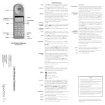
1-3.
Names of External Components
Zoom ring
Power switch
Focus ring
Shutter button
Exposure compensation button
Continuous shooting button
Mode dial
Microphone
Flash
Focus mode selector switch
(One-touch AF) button
Strap mount
AF-assist illuminator
/Self-timer lamp
Speaker
Slot cover
Lens hood
Terminal cover
A/V OUT (Audio/
Visual output) socket
xD-Picture Card slot
DC IN 5V (power input)
socket
USB socket (mini-B)
1-5
1. General
FinePix S6000fd/S6500fd Service Manual
Diopter adjustment dial
Viewfinder (EVF)
Intelligent Face Detection button
EVF/LCD (monitor selector) button
Indicator lamp
Digital zoom button
4-direction (
LCD monitor
DISP (Display)/
BACK button
Tripod mount
1-6
) button
MENU/OK button
Photo mode (
Battery cover
) button
2. Disassembly
FinePix S6000fd/S6500fd Service Manual
2. Disassembly
2-1.
Names of internal Components
MSW PWB ASSY
R CASE ASSY
KSW PWB ASSY
FRAME LCD
LCD CONST
REINFORCEMENT LCD
FLASH CONST
RSW PWB ASSY
MAIN PWB ASSY
EVF UNIT CONST
ASSY HOLDER BATTRY
LID BATTRY
MIC ASSY
FLASH PWB ASSY
MAIN FRAME
SSW PWB ASSY
LENS HOLDER
SPEAKER ASSY
F CASE ASSY
LENS ASSY
2-1
2. Disassembly
2-2.
FinePix S6000fd/S6500fd Service Manual
Removing the REAR CONST
(1) Remove the 2 screws (M1.7 x 9.0).
(2) Remove the 3 screws (M1.7 x 3.5).
2
1
2
(3) Apply pressure in the direction of the arrow to
disengage the catch for section A.
(4) Slowly remove the REAR CONST in the direction of
the arrow.
A
3
A
A
3
4
2-2
2. Disassembly
FinePix S6000fd/S6500fd Service Manual
(5) Unlock the connector and remove the LCD FPC.
(6) Unlock the connector and remove the MAIN-KSW
FPC.
5
6
[Notes on Assembly]
Fit the REAR CONST into the F CASE with the CARD
COVER open (to prevent damage to SW551).
[Assembly]
Assemble by performing the disassembly procedure in
reverse.
SW552
2-3
2. Disassembly
2-3.
FinePix S6000fd/S6500fd Service Manual
Disassembling the REAR CONST
(1) Remove the 4 screws (M1.7 x 4.0).
8
1
(2) Remove the 4 screws (M1.7 x 4.0B).
(3) Remove the LCD FRAME.
(4) Unlock connector CN802 and remove the KSW-MSW
FFC.
(5) Remove the screw (M1.7 x 4.0).
5
6
2
(6) Press the MSW-PWB locking catch in the direction of
the arrow to release it.
(7) Remove the MSW-PWB in the direction of the arrow.
7
9
3
(8) Remove the 2 screws (M1.7 x 4.0).
4
(9) Remove the KSW-PWB in the direction of the arrow.
(10) Remove the LCD CONST in the direction of the arrow.
(11) Remove the FACE BUTTON in the direction of the
arrow.
14
15
(12) Remove the REAR BUTTON in the direction of the
arrow.
(13) Remove the CURSOR ASSY in the direction of the
arrow.
(14) Remove the screw (M1.7 x 4.0).
(15) Remove the STRAP RIGHT in the direction of the
arrow.
[Notes on Assembly]
When installing the MSW PWB in the R CASE, set the
MODE DIAL to "AUTO" and set the selector dial on the
MSW PWB to the position shown in the figure on the right.
[Assembly]
Assemble by performing the disassembly procedure in
reverse.
2-4
12
11
13
10
2. Disassembly
FinePix S6000fd/S6500fd Service Manual
2-4.
Removing the MAIN PWB ASSY and FLASH PWB ASSY
(1) Remove the 2 wire harnesses in the direction of the
arrow.
4
(2) Remove the 2 FPCs in the direction of the arrow.
(3) Remove the 2 FFCs in the direction of the arrow.
1
3
2
(4) Remove the EVF UNIT in the direction of the arrow.
(5) Unlock the connector and remove the CCD FPC.
2
3
1
5
(6) Unlock the connector and remove the LENS MOTOR
FPC.
(7) Remove the 3 screws (M1.7 x 2.5).
7
8
6
B to B
CONNECTOR
(8) Remove the B to B CONNECTOR and then remove
the MAIN PWB ASSY in the direction of the arrow.
2-5
2. Disassembly
(9) Peel off the TAPE CONDENSER.
FinePix S6000fd/S6500fd Service Manual
12
(10) Discharge the main capacitor.
Take care not to touch the main capacitor terminals
before discharging the capacitor.
11
(11) Push the connector catch upwards.
10
(12) Remove the connector (FLASH CONST) in the
direction of the arrow.
9
15
(13) Remove the connector (BATTERY CONST) in the
direction of the arrow.
(14) Remove the 4 screws (M1.7 x 2.5).
(15) Push the FLASH PWB ASSY to the right and remove
the AV jack alignment guide. Then pull the assembly
outwards to remove it.
[Notes on Assembly]
Align the bosses for the FLASH PWB ASSY and F CASE
so that they interlock in the correct position.
[Assembly]
Assemble by performing the disassembly procedure in
reverse.
2-6
13
J702
14
FinePix S6000fd/S6500fd Service Manual
2-5.
2. Disassembly
Removing the HOLDER BATTERY
(1) Remove the screw (M1.7 x 9.0).
(2) Remove the HOLDER BATTERY in the direction of
the arrow.
1
2
[Notes on Assembly]
During HOLDER BATTERY assembly, set the RELEASE
LEVER to OFF (to prevent damage to SW902 and
SW903).
[Assembly]
Assemble by performing the disassembly procedure in
reverse.
2-7
2. Disassembly
2-6.
FinePix S6000fd/S6500fd Service Manual
Removing the LENS ASSY
(1) Remove the 2 screws (M1.7 x 4.0).
1
(2) Remove the MAIN FRAME in the direction of the
arrow.
2
(3) Remove the 4 screws (M2.0 x 10.0).
(4) Remove the LENS ASSY in the direction of the arrow.
3
4
[Notes on Assembly]
Arrange the CCD FPC GND flap as shown in the figure on
the right.
[Assembly]
Assemble by performing the disassembly procedure in
reverse.
2-8
2. Disassembly
FinePix S6000fd/S6500fd Service Manual
2-7.
Removing the LENS HOLDER
(1) Remove the wire harness (SPEAKER).
1
(2) Remove the 4 screws (M2.0 x 9.0).
(3) Remove the LENS HOLDER in the direction of the
arrow.
3
2
1
(4) Remove the wire harness (MIC).
4
(5) Remove the screw (M1.7 x 4.0).
(6) Remove the SSW PWB ASSY in the direction of the
arrow.
6
5
2-9
2. Disassembly
[Notes on Assembly]
• Arrange the MIC wire harness as shown in the figure on
the right.
• Arrange the SPEAKER wire harness as shown in the
figure on the right.
• Assemble with the focus mode selector switch set to the
"S" position.
[Assembly]
Assemble by performing the disassembly procedure in
reverse.
2-10
FinePix S6000fd/S6500fd Service Manual
2. Disassembly
FinePix S6000fd/S6500fd Service Manual
2-8.
Removing the FLASH CONST
(1) Remove the 2 screws (M1.7 x 4.0).
2
1
(2) Remove the FLASH CONST in the direction of the
arrow.
[Assembly]
Assemble by performing the disassembly procedure in
reverse.
2-9.
Removing the FRONT CONST
(1) Remove the 2 screws (M1.7 x 4.0).
4
(2) Remove the AFLED CONST in the direction of the
arrow.
1
5
(3) Remove the SPEAKER ASSY in the direction of the
arrow (taking care not to pull the wire harness).
3
2
(4) Remove the screw (M1.7 x 4.0).
(5) Remove the STRAP LEFT in the direction of the
arrow.
(6) Remove the COVER JACK in the direction of the
arrow.
6
[Assembly]
Assemble by performing the disassembly procedure in
reverse.
2-11
2. Disassembly
FinePix S6000fd/S6500fd Service Manual
2-10. Specifications for the sheet component attachment locations
2-10-1. Affixing the REINFORCEMENT LCD
(1) Attach the LCD FRAME TAPE to the LCD FRAME as
shown in the figure on the right.
(2) Align the LCD FRAME bosses and attach the
REINFORCEMENT LCD.
2-12
FinePix S6000fd/S6500fd Service Manual
2. Disassembly
2-10-2. Affixing the MF SHEET
(1) Attach the MF SHEET to the MAIN FRAME as shown
in the figure on the right.
(2) Stick the UL TAPE around the central section of the
MF SHEET, ensuring that the MF SHEET and the EMI
SHEET CCD on the CCD FPC are not touching.
Tape size: 24 ± 2 mm x 19 mm
2-10-3. Affixing the FLASH PWB GASKET
(1) Affix as shown in the figure on the right.
2-13
2. Disassembly
MEMO
2-14
FinePix S6000fd/S6500fd Service Manual
3. Schematics
FinePix S6000fd/S6500fd Service Manual
3. Schematics
3-1.
Cautions
<Cautions when replacing parts>
• Do not reuse removed parts. Always use new parts.
• Note that the negative side of tantalum condensers is readily damaged by heat.
• Except for chemical condensers and tantalum condensers, voltage is not displayed on condensers with a voltage
resistance of 50V or less.
• Resistors not marked are 1/16W chip resistors.
• KΩ = 1000Ω, MΩ = 1000KΩ
• B characteristics of variable resistors and semi-fixed resistors are not displayed.
3-2.
Basic Block Names and Functions
Part name
LENS ASSY
MAIN PWB ASSY
KSW PWB
FSW PWB
MSW PWB
RSW PWB
XE PWB
SSW PWB
Block name
CCD FPC BLOCK
AV BLOCK
CAMERA BLOCK
DCDC BLOCK
EVF BLOCK
FDI BLOCK
FLASH JACK BLOCK
KEY BLOCK
LCD BLOCK
MOTOR BLOCK
PMAN BLOCK
PROCESS BLOCK (IO)
PROCESS BLOCK (PW)
PROCESS BLOCK (SYS)
AF LED BLOCK
CN BLOCK
EMI BLOCK
LCD DATA7 BLOCK
MEDIA BLOCK
PLUNGER BLOCK
USB BLOCK
KSW BLOCK
FSW BLOCK
MSW PWB
RSW PWB
XE BLOCK
SSW BLOCK
Function
CCD Output
Audio/Video IN/PIT (IC281)
CCD Output A/D Conversion (IC102)
Power Supply Generation (I301, IC305), Power Control
EVF Control (IC452)
Face Detection Signal Processing (IC651)
Flash Charge and Discharge
SSW Input, RSW Input, KSW Input
LCD Output CN, Back Light Control
Shutter/Iris/AF Drive (IC151)
Power Control, LED Driver, Flash Charge Control (IC401)
Image Signal Processing (IC201: 1/3)
Power Input (IC201: 2/3)
System Control, USB Communications (IC201: 3/3)
AF_LED Output
Connection with the FLASH PWB
High Frequency Noice Reduction
LCD Signal Compensation
Media Data IN/OUT
Flash Pop-up
USB Signal IN/OUT
Key Switch, Interface for MSW
Flash Pop-up Detection
Camera Mode Select
Release, Camera/Play/Power, +/- Drive Input
Flash Firing
Mic, One-touch AF, AF/MF/C-AF Input, Speaker Output
3-1
3. Schematics
FinePix S6000fd/S6500fd Service Manual
3-3.
Description of Main Block Functions
3-3-1.
Technical Overview
The FinePix S6000fd/S6500fd features the new "Face Kirei-Navi" function -- the world's fastest face detection function -developed using the "Image Intelligence?" ultra-high quality digital image processing software. You just press a button to set
"Face Kirei-Navi" and the camera can detect up to 10 people's faces at once in as little as 0.05 seconds. It then focuses on a
person's face and automatically selects the correct brightness for that face.
Thanks to the super-efficient light capturing capacity of the "Super CCD Honeycom VI HR" and the "Real Photo Engine II"
image processing engine, the FinePix S6000fd/S6500fd can shoot full-pixel images with 6.3 million effective pixels even at
ultra-high sensitivities of ISO 3200. It also features "iFlash", which recognizes the distance to the main subject of the shot and
gauges the subject's size and position in the overall image. This enables it to automatically select the ideal flash brightness
and sensitivity setting so that features such as skin tones are captured perfectly with no flaring.
The 10.7x zoom lens provided on the FinePix S6000fd uses high-definition Fujinon optics and an ultra-wide 28-300 mm focal
range, so you can use just one lens for almost any type of shot. At 28 mm it is perfect for landscapes and snapshots while the
300 mm focal length is ideal for sporting events, concerts and portraits. The S6000fd/S6500fd is packed with functions built
around the latest FUJIFILM technology, including the popular "high sensitivity dual-shot" function, which lets you record 2
continuous images of the same shot, one taken with the flash and one without. Also included is the Picture Stabilization mode
for truly impressive telephoto images and crystal-clear shots of sporting events.
CCD signal processing/Camera circuit section
Analog signals output from the 1/1.7 type Super-CCD Honeycom VI HR (IC951), with an effective pixel count of 6.3
mega-pixels, undergo false color compensation processing, adaptive interpolation processing, amplification (AGC) and
signal mixing inside the CCD signal processing IC “BCS_MCM (IC102)” before being converted to 14-bit digital signals
(A/D) and sent to the signal processing LSI “NCS_L (IC201)”.
The CCD drive circuit, H drive, and V drive are installed in [BCS_MCM (IC102)].
Motor Circuit Section
The signal processing LSI “NCS_L (IC201)” that has received various operating switch commands manages the motor
drive IC (IC151) and controls the AF, SHUTTER, ZOOM and IRIS motors.
Imaging and Signal Processing Section
Input data from the CCD
14-bit digital image data (corresponding to 1H) that has been output from the imaging section (CCD/Camera Block) is
sent to the signal processing LSI “NCS_L (IC201)”, converted to 32-bit (16-bit x 2) data by the [internal buffer] inside this
LSI, and the image data for one frame (2848 x 2136 pix) is stored temporarily in [SD-RAM]. It is also integrated in the
[AUTO operation section] using the 32-bit the signal processing LSI “NCS_L (IC201)” image data and sent to the
BCS_MCM (IC102) to obtain the appropriate AE/AF/AWB.
Record processing to xD Card
Image data stored in SD-DRAM is sent one frame at a time to the internal [signal processing section] in the signal
processing LSI “NCS_L (IC201)”. In a process called unpacking, “32-bit to 12-bit conversion” and “pre-processing
including digital clamp, white balance and noise reduction processing, linear matrix processing, gamma correction and R/
G/B 14-bit to R/G/B 8-bit conversion” to “8-bit digital R/G/B signals to Y:Cb:Cr = 4:2:2 YC processing” are implemented in
this [signal processing section] and 8-bit Y/Cb/Cr image data are sent to the [internal buffer].
The “rearrangement of data in a format in which 8-bit Y/Cb/Cr signals are easily compressed” is done in the [internal
buffer] and after passing through the [JPEG operation block] to the [media controller], they are recorded on the xD card.
Reproduction of images from xD card
Compressed image data from the xD card is sent as 8-bit image data to the signal processing LSI “NCS_L (IC201)” then
it is sent to the [media control section], the [DMA unit] and the SD-DRAM and then it is sent to the [media controller], to
the [JPEG operation section] and to the [signal processing section].
In the [signal processing section], 8-bit Y/Cb/Cr signals are converted to 8-bit R/G/B signals and at the same time,
lettering display signals are weighted and passed through the [LCD controller to the LCD unit and displayed.
Image capture system adjustment data are stored in the Flash ROM.
LCD Unit
Digital signals from the signal processing LSI "NCS_L (IC201)" are sent directly to the LCD. And signals processed by the
EVF CONTROL IC (IC452) are sent to the EVF.
Power Supply Section
Power supply circuits constructed in the core of the DC IC (IC300) create the following power supplies, which are
supplied to each block.
+3.3VRUN
[IC281 (AV BLOCK), IC501 (AF LED BLOCK)]
+3.3VDOUT
[IC401 (PMAN BLOCK), IC201 (NCS_L), IC457 (LCD DATA7 BLOCK), CN261 (MEDIA BLOCK),
IC271 (AV BLOCK), IC452 (EVF BLOCK), IC151 (MOTOR BLOCK)]
+3.3VAOUT
[IC452 (EVF BLOCK), IC201 (NCS_L)]
+15VRUN
[IC102 (CAMERA BLOCK)]
+5VAD
[IC102 (CAMERA BLOCK), IC451 (LCD BLOCK), IC401 (PMAN BLOCK)]
+3.3VCAM
[IC102 (CAMERA BLOCK)]
+5VRUN
[Q452 (EVF BLOCK), IC451 (LCD BLOCK), IC401 (PMAN BLOCK)]
+1VNCS
[IC651 (FDI BLOCK), IC401 (PMAN BLOCK)]
+3.3VNCS
[IC651 (FDI BLOCK), IC401 (PMAN BLOCK)]
+5VMOT_VM1
[IC151 (MOTOR BLOCK)]
+5VMOT_VM2
[IC151 (MOTOR BLOCK)]
+2.5VRUN
[IC201 (NCS_L)]
+1VRUN
[IC201 (NCS_L)]
-8V
[IC951 (CCD FPC BLOCK)]
15V
[IC951 (CCD FPC BLOCK)]
3-2
3. Schematics
FinePix S6000fd/S6500fd Service Manual
3-4.
LED Dr
TK11880F-G
JTAG
A FLED_EVR
AFLED_ON
IC501
HA-CCD
MS3897A
1 /1. 7i nc h
6.3millon pixels
WIDE/TELE Variable
CDS
Focus HP
Zoom position
IRIS HP
Cont. 16V
Pulses
ØV
5V
ØH
R EC C
CAM_D0_M
CAM_D1_M
CAM_SCK_M
Gr a y
Code
EVR
TG
(Programable)
C GEN
F DI _D [ 13: 0]
FDI_HD/FDI_VD
FDI_AD_CLK
CCD_VSEL,CAM_ON
Fo cus P ulse * 3 ,Z oom P ul se * 3
MT R_ C S
Fa c e D et e c t I C
T6UC9XBG
-0001
3.3V
SW
IC651
FDI_INT
FDI_CLK
FDI_CS_N
FDI_RESET_N
SI0_1
SI0_2
FDI_PLLBP
FDi1_ON,FDI33_ON
I-cache D-cache
8k
8k
STB_SY
FLASH-XE
IPS2
A N 3020 4
IC451
LE D _R
LED_G
CTL
LED
DRIVER
x3
S I0 _2
MFT
VIDEO_ON
DA C
I/O Buffer
ROM
8kb x32
AUDIO
A M CL K
A F CL K , A B C L K
SPEAKER
2
IS
A ADIN
ADAOUT
DA
SP_AMP
AD
MIC_AMP
MIC
C TL
A U _ MU TE
SIO_3
VCLK ON
PWR_SW
NT/PAL SEL
CCDCLK ON
RESET
DC/DC Block
A N 3 02 12
CCD_ON
D C / D C IC .
DC/DC Block
MB39C014PV
DC/DC IC.
1ch
BATT.
ALKALI
4x
FLASH
PWB
AV-LSI
XE01106
V i de o
D r i v er
256Mb x32
5ch
AV
JA CK
C L KC
3 .3 V
PLAY_SW
FUSE
B AT _V
3.3V_ON
DC _J AC K
5V
Cradle
Not
Supportted
AU_OUT
PORT
BUS C on t.
SDRAMC
DMAC
S DR AM
R e se t
0 . 9 VRe se
PWCTL
FLASH PWB
M i ni
USB
A U_CS
Power on
X’TAL
FC-255
32.768kHZ
X400
A U_BEEP
AV_DET
BUS x32
D 3. 3V
1.0V
BL LED x3
ICU
I PS _C S,I PS _ A CT , ST RB _C C
RTC
BATT
Backu p
NCS_L 3.3V Operation
C TL
USB2.0
2
X’TAL
CX-101F
48.00MHz
X201
BL LE D
D r i v er
CSIO
IS
FLASH CTRL
L CD P a n e l
( C as i o )
2.5inch
VIDEO_OUT
JPEG
CCDCLK(36MHz)
IC401
LC D_ B L_ EV R /EV L_BL_O N
WDT
Detect system
FLASH_POP
EVF BL
SIO_3
A R M1 13 6J- S Cor e
CPU Core
EVF
(SANYO)
0.33inch
LC D D A T [7 : 0] ,L C D_ C LK ,
LCD_HD,LCD_VD
TFDC
E NC D
SI0_1
IC151
IC452
LC15009A
CTL
UART
YCPRO
xD Card
DR_SW
DEBUG I/F
SHT PULSE * 2
Card
Slot
(2 0 P IN )
M EDIA
OFD
Motor Drv.
R2A30404NP
7ch
CTL
AUTO
BCS_CS,BCS_RESET
V
Driver
MDA_ON
CCDIF
Digital
Ga i n
H
Driver
CCD
Power
Select
SW
FLASH
128Mbit (NAND)
IBFC
CAM_D0_P
CAM_D1_P
CAM_SCK_P
ADC
14bit
IC951
SIP
MC-10036F1
IC201
CARD BUS
BCS
AD9926
3.3V Operation
IC102
CCDIN
O.LPF
10xZOOM LENS
IRIS 10Steps
D 3 . 3V
OFD_EVR
Peripheral BUS 120MHz
AF ASSIST LED
MAIN PWB
Series
REG
3.5V
DR_SW
5.2V
Block Diagram
48MHz
Clock Generator
V I D EO
Clock Generator
CA M
IC281
27MHz
KEY
R E L E A S E S W ( S 1/ S 2)
R/L/D/U SW
OK/BACK/F SW
E V F_ LC D S W
MODE SW(11pos)
BRIGHT SW
DRIVE/+- SW
1.0V
5V
IC305
EV3
CCD15V
CCD-8V
A D _3. 3V ,
2 .5 V
POWER SW
IC301
Series
REG
3.3V
Series
REG
2.5V
C AM / PL AY S W
3-3
3. Schematics
Overall connection Diagram
EVF UNIT
LCD UNIT
C
C
C
A
A
A
1
2
3
4
5
6
7
8
9
10
11
12
13
14
15
16
17
18
19
20
GND
CARD
R/B
RE
CE
CLE
ALE
WE
WP
GND
D0
D1
D2
D3
D4
D5
D6
D7
VCC
VCC
XD_CARD_CN
FGY088-0201
AF LED BLK
MAIN PWB
AUDIO_BLOCK
POWER ON BLK
POP_DET
GND
GND
PLUMGERPLUMGER+
1 2
STRB PWB
1
2
3
XETRIGGER C 4
XE+
TRIGGER
XE+
XE-
XE
SPEAKER
UNIT
SSW_FFC
PLUMGER_UNIT
GND
MSW
PWB
GND
OK/BAKC/F_SW
FDI_SW
RLDU_SW
GND
GND
GND
AD_3.3V
M IC C
GND
GND
PLUMGERPLUMGER+
FGB164-0101
10FLZ-RSM2-GB-TBLFSN
KSW
PWB
2
1
FGA162-0021
1
GND
2
AD 3.3V
MODE_DIAL 3
4
GND
5
GND
6
GND
1
2
3
4
5
6
GND
AD 3.3V
MODE_DIAL
GND
GND
GND
FGB162-0061
6FLT-SM2-GB-TBLFSN
RSW PWB
SPEAKER+
SPEAKER-
KSW FFC
GND
MODE_DIAL
FGB165-0121
12FHJ-SM1-GB-TBLFSN
FGA162-0022
POP_DET
1 2 3 4 5 6 7 8 9 10
FGB163-0061
6FLZ-SM2-GB-TBLFSN
STRB BLK
UNREG_BAT
UNREG_GN
BATT
CGP4702-0101F
FGA169-0021
STRB PWB
FGA173-0041
S04B-PASK-2(LF)(SN)
1 2 2
FZ04171-100
HEC3654-012010
DC CN
UNREG
ADP_DET
UNREG_GN
AV_JACK
FZ04722-100
HSJ1660-019575
VIDEO BLK
GND
GND
S1_SW
S2_SW
EV3
PW_SW
D_3.3V
+DRIVE
CAM_SW
GND
GND
GND
GND
GND
VBS
GND
GND
AV_DET
AV_OUT
IGBT_GDR
GND
BSTSEC
GND
BSTVS
GND
BSTGDR
GND
BSTVD
GND
GND
GND
UNREG
UNREG
UNREG
UNREG
UNREG
UNREG
UNREG
UNREG
UNREG
UNREG
FGC189-0301
9842B-30Y900
OK/BAKC/F_SW
10 9 8 7 6 5 4 3 2 1
FDI_SW
GND
MODE_DIAL
1 2 3 4 5 6 7 8 9 10 11 12
RLDU_SW
GND
GND
GND
AD_3.3V
GND
GND
S1_SW
S2_SW
EV3
PW_SW
D_3.3V
+DRIVE
CAM_SW
GND
GND
1 2 3 4 5 6 7 8 9 10 11 12 13 14 15 16 17 18 19 20 21 22 23 24 25 26 27 28 29 30
1 2 3 4 5 6 7 8 9 10 11 12 13 14 15 16 17 18 19 20 21 22 23 24 25 26 27 28 29 30
5
4
3
2
1
FGB164-0101
10FLZ-RSM2-GB-TBLFSN
1 2 3 4 5 6 7 8 9
12 11 10 9 8 7 6 5 4 3 2 1
12 MIC GND
11 MIC+
10 MIC GND
9 MIC FIL
8 GND
7 PAF UIF N
6 GND
5 MCAF2
4 GND
3 MCAF 1
2 SPEAKER1 SPEAKER+
FSW_PWB
GND
GND
GND
VBS
GND
GND
AV_DET
AV_OUT
IGBT_GDR
GND
BSTSEC
GND
BSTVS
GND
BSTGDR
GND
BSTVD
GND
GND
GND
UNREG
UNREG
UNREG
UNREG
UNREG
UNREG
UNREG
UNREG
UNREG
UNREG
FGB165-0121
12FHJ-SM1-GB-TBLFSN
1
2
3
4
5
6
7
8
9
10
11
12
PSW FF
FGC188-0301
9831S-30Y950
USB_CN
FZ05744-100
CAM-G71SDF
MIC GND
MIC+
MIC GND
MIC FIL
GND
PAF UIF N
GND
MCAF2
GND
MCAF 1
SPEAKERSPEAKER+
HARNESS
FGA164-0051
SM05B-SRSS-TB
FGB165-0121
12FHJ-SM1-GB-TBLFSN
PROCESS BLK
FGB165-0121
12FHJ-SM1-GB-TBLFSN
SSW_PWB
RSW FFC
3-4
AF
AF
AF
AF
AF
AF
STH
VSS
CKH2
CKH2
VDD
CSH
G
R
B
DSG
DSD
VBB
CSV
ENB
STV
CKV1
COM
N.C
EVF BLK
LED
LED
LED
LED
LED
LED
VCOM
D07
D06
D05
D04
D03
D02
D01
D00
CS
DI
SCK
VSYNC
HSYNC
CLK
VSS
VSS
PCB
VBC
VSREF
COMDC
VDD
VDD2
C1P
C1M
C2M
C2P
VDD
COMOUT
VVCOM
VSS
VSS
C3M
C3P
C4M
C4P
VDD3
C5M
C5P
VGH
C6P
C6M
VGL
FB
BL VCC
LCD BLK
FGB165-0061
6FHJ-SM1-GB-TBLFSN
V_BUS
DD+
ID
GND
FRAME
FRAME
FRAME
FRAME
SHUTTER1
SHUTTER2
I A
I /A
I B
I /B
3.3V
FPJ E1
FPJ C1
FPJ E2
FPJ C2
F A
F B
F /A
F /B
3.3V
FPI C1
FPI E1
MOT EN 25
MOT EN 24
MOT EN 23
MOT EN 22
MOT EN 21
GND
1 2 3 4 5 6
FGB162-0181
18FLT-SM2-GB-TBLFSN FGA164-0021
SM02B_SRSS
CAM BLK
24
23
22
21
20
19
18
17
16
15
14
13
12
11
10
9
8
7
6
5
4
3
2
1
18 17 16 15 14 13 12 11 10 9 8 7 6 5 4 3 2 1
FGB167-0451
FF12A-45A-R11B
MOTOR BLK
16V
16V
16V
CCD OUT
CCD OUT
GND
GN D
GND
RS
H1
H2
H4
H3
H5
H6
H8
H7
GND
GND
GND
OFD
GND
GND
GND
LM
V8
V7
V6
V5
V4B
V4A
V3B
V3A
V2B
V2A
V1B
V1A
-8V
-8V
EVF FPC
1 2 3 4 5 6 7 8 9 10 11 12 13 14 15 16 17 18 19 20 21 22 23 24 25 26 27 28 29 30 31 32 33 34 35 36 37 38 39 40 41 42 43 44 45
FGB180-1391
501628-3991
39
38
37
36
35
34
33
32
31
30
29
28
27
26
25
24
23
22
21
20
19
18
17
16
15
14
13
12
11
10
9
8
7
6
5
4
3
2
1
XE01138
24FKZ-SM1-1-TB
MOTOR FPC
LENS UNIT
CCD_FPC
LCD FPC
AF LED
EVF BL
3-5.
FinePix S6000fd/S6500fd Service Manual
MIC_UNIT
FinePix S6000fd/S6500fd Service Manual
3. Schematics
3-6.
Circuit Diagrams
3-6-1.
AV BLOCK
3-5
3. Schematics
3-6-2.
3-6
CAMERA BLOCK
FinePix S6000fd/S6500fd Service Manual
FinePix S6000fd/S6500fd Service Manual
3. Schematics
3-6-3.
DCDC BLOCK
3-7
3. Schematics
3-6-4.
3-8
EVF BLOCK
FinePix S6000fd/S6500fd Service Manual
FinePix S6000fd/S6500fd Service Manual
3. Schematics
3-6-5.
FDI BLOCK
3-9
3. Schematics
3-6-6.
3-10
FLASH JACK BLOCK
FinePix S6000fd/S6500fd Service Manual
FinePix S6000fd/S6500fd Service Manual
3. Schematics
3-6-7.
KEY BLOCK
3-11
3. Schematics
3-6-8.
3-12
KSW BLOCK
FinePix S6000fd/S6500fd Service Manual
FinePix S6000fd/S6500fd Service Manual
3. Schematics
3-6-9.
LCD BLOCK
3-13
3. Schematics
3-6-10. MOTOR BLOCK
3-14
FinePix S6000fd/S6500fd Service Manual
FinePix S6000fd/S6500fd Service Manual
3. Schematics
3-6-11. PMAN BLOCK
3-15
3. Schematics
3-6-12. PROCESS BLOCK (IO)
3-16
FinePix S6000fd/S6500fd Service Manual
FinePix S6000fd/S6500fd Service Manual
3. Schematics
3-6-.13 PROCESS BLOCK (PW)
3-17
3. Schematics
3-6-14. PROCESS BLOCK (SYS)
3-18
FinePix S6000fd/S6500fd Service Manual
FinePix S6000fd/S6500fd Service Manual
3. Schematics
3-6-15. AF LED BLOCK
3-6-16. CCD FPC BLOCK
3-19
3. Schematics
3-6-17. CN BLOCK
3-6-18. FSW BLOCK
3-20
FinePix S6000fd/S6500fd Service Manual
FinePix S6000fd/S6500fd Service Manual
3. Schematics
3-6-19. EMI BLOCK
3-21
3. Schematics
3-6-20. LCD DATA 7 BLOCK
3-22
FinePix S6000fd/S6500fd Service Manual
FinePix S6000fd/S6500fd Service Manual
3. Schematics
3-6-21. MEDIA BLOCK
3-6-22. MSW BLOCK
3-23
3. Schematics
3-6-23. PLUNGER BLOCK
3-6-24. USB BLOCK
3-24
FinePix S6000fd/S6500fd Service Manual
FinePix S6000fd/S6500fd Service Manual
3. Schematics
3-6-25. RSW BLOCK
3-6-26. XE BLOCK
3-25
3. Schematics
3-6-27. SSW BLOCK
3-26
FinePix S6000fd/S6500fd Service Manual
3. Schematics
FinePix S6000fd/S6500fd Service Manual
3-7.
Mounted Parts Diagrams
3-7-1.
FSW PWB ASSY
A
B
C
D
E
F
1
2
3
4
3-27
3. Schematics
3-7-2.
FinePix S6000fd/S6500fd Service Manual
KSW PWB ASSY
A
B
C
D
E
F
1
3-28
2
3
4
3. Schematics
FinePix S6000fd/S6500fd Service Manual
3-7-3.
MSW PWB ASSY
A
B
C
D
E
F
1
2
3
4
3-29
3. Schematics
3-7-4.
FinePix S6000fd/S6500fd Service Manual
RSW PWB ASSY
A
B
C
D
E
F
1
3-30
2
3
4
3. Schematics
FinePix S6000fd/S6500fd Service Manual
3-7-5.
SSW PWB ASSY
A
B
C
D
E
F
1
2
3
4
3-31
3. Schematics
3-7-6.
FinePix S6000fd/S6500fd Service Manual
XE PWB ASSY
A
B
C
D
E
F
1
3-32
2
3
4
3. Schematics
FinePix S6000fd/S6500fd Service Manual
3-7-7.
FLASH PWB ASSY
A
B
C
D
E
F
1
2
3
4
5
6
7
8
9
3-33
3. Schematics
3-7-8.
FinePix S6000fd/S6500fd Service Manual
MAIN PWB ASSY
A
B
C
D
E
F
1
3-34
2
3
4
5
6
7
8
9
FinePix S6000fd/S6500fd Service Manual
4. Adjustments
4. Adjustments
4-1.
Important point before Adjustment
4-1-1.
The handling of image files in internal memory
This camera has internal memory, image files stored in the internal memory should be handled as described below when the
camera is replaced or repaired.
Take particular care to ensure that the customers images are not erased.
<Procedure for handling images>
When either of following work is necessary, extract as many as possible of the image files stored in the internal memory. Then,
after the camera is repaired or replaced, load the images into the internal memory in the camera before the camera is
returned to the customer.
1. When the replacement camera is provided.
2. When the MAIN PWB ASSY is replaced.
--->When "MAIN PWB ASSY" is replaced, it is necessary to execute "Flash memory reset".
(When the "Flash memory reset" was executed, involve formatting the internal memory.)
<Image file transfer procedure>
I. Procedure when images can be downloaded to a PC
* If an xD-Picture card is inserted, data in the internal memory cannot be backed up.
(1) Back up the images stored in internal memory.
• Create a folder (named and located so as to avoid any confusion with the user's images).
• Without inserting an xD-Picture card, connect the camera to a PC and copy the image files on the removable disk
recognized by the PC to the folder created in the previous step.
• Check that the images can be displayed correctly on the PC.
(2) Return the backed up image files from the PC to the camera.
• Turn the camera on without an xD-Picture card inserted and format the camera's internal memory.
• Without inserting an xD-Picture card, connect the camera to the PC and copy the image files from the folder
containing the images backed up in the previous step onto the removable disk recognized by the PC.
• Check that the images can be displayed correctly on the camera.
• Delete the backup files created on the PC in step (1) (the user's image files).
II. Procedure when images cannot be downloaded to a PC
(1) Back up the images stored in internal memory.
• Insert an xD-Picture card to be used for image backup into the camera and format the card.
• From the SETUP menu, reset the frame numbers.
• Select image copying from the playback menu, select "Camera -> Card" for all the frames and then copy the images.
• Check that the images can be displayed correctly on the camera.
(2) Return the backed up image files from the xD-Picture card to the camera.
• Before inserting the card, format the camera's internal memory.
• Insert the xD-Picture card containing the backed up copies of the user's image files.
• From the SETUP menu, reset the frame numbers.
• Select image copying from the playback menu, select "Card -> Camera" for all the frames and then copy the images.
• Remove the xD-Picture card and check that the images can be displayed correctly on the camera.
• From the SETUP menu, set the frame numbers to the default sequence.
• If the image file numbers have changed, always notify the user in writing that the image file numbers have changed.
4-1
4. Adjustments
4-1-2.
FinePix S6000fd/S6500fd Service Manual
Important point Adjustment when Replacing Major Parts
Adjust the item shown by ¡ in the table below at the part replacement of LENS ASSY, MAIN PWB, FLASH ASSY and LCD
CONST. (Other part replacements need not be adjusted.)
Replacing parts
Adjustment item
0 Flash memory reset*
1 CCD Defect Correction/OFD adjustment
2 Camera adjustment
3 Shading compensation adjustment
4 AF adjustment
5 Flash adjustment
6 Battery adjustment
7 Mode dial adjustment
8 Video adjustment
9 LCD adjustment
10 Firmware download
11 End setting
LENS ASSY
MAIN PWB
FLASH ASSY
LCD CONST
{
{
{
{
{
{
{
{
{
{
{
{
Do not use it until there is an instruction.
(Do the end setting when you end the adjustment software when you set the camera to the Jig mode)
{
{
{
{
{
{
* When the MAIN PWB ASSY is replaced, the camera will not operate normally unless the MAIN PWB is initialized.
4-2.
Measuring Instruments Used
Measuring equipment
Regulated power supply
Pattern box
Digital voltmeter
PC
Brightness meter
Color temperature meter
Flash meter
Remarks
For adjustment
PTB450F
For Battery adjustment
Used for various adjustments and operation checks (PC-AT compatible, Win 2000 / XP) *1
It is necessary to install Microsoft .NET Framework Ver1.1.*2
LS-110 (Minolta) or equivalent
Color Meter IIIF (Minolta) or equivalent
Used for function checks
*1: PC condition
1. Hardware recommendation: CPU;Pentium4 2.4GHz or better, RAM;512MB or more.
It might make an error of the adjustment when the performance of PC is low.
2. Video Jig and LCD Jig must be installed.
*2: Download it from the homepage of the Microsoft.
Microsoft .NET Framework Version 1.1
http://www.microsoft.com/downloads/details.aspx?familyid=262d25e3-f589-4842-8157-034d1e7cf3a3&displaylang=en
4-2
FinePix S6000fd/S6500fd Service Manual
4-3.
4. Adjustments
Use Jig list
Pats.No
ZJ00006-100
ZJ00008-100
ZJ00009-100
ZJ00254-100
FZ06705-100
ZJ00998-100
ZJ00684-100
ZJ00580-100
ZJ00611-100
ZJ00583-100
ZJ00653-100
ZJ00650-100
ZJ00553-100
ZJ00999-100
FZ06229-100
FZ03983-100
FZ03982-100
FZ00330-200
ZJ00581-100
Name
Filter LB140
Lens holder
Stand
Gray Chart (Reflective type)
USB cable
FxS6000fd_6500fd W PC Soft Ver.1.00
DSC JIG Driver Install.exe
Power Cable Jig
X-Y stage for AF adjustment
Screw Driver (D3LUFX88G (2X20))
LB140 filter holder kit for X-Y stage
Video adjustment jig
AF solid chart
CCD data for FxS6000fd/S6500fd
Video cable
AC Cable (For EG)
AC Cable(For EU)
AC Cable (For US/JP)
Discharger
Comment
Camera adjustment
AF adjustment
AF adjustment
Flash adjustmen
General adjustment
PC adjustment
For PC setup
Battery / Mode dial adjustment
General adjustment
General repair
Camera adjustment
Video adjustment
General adjustment
CCD Data Input
Video adjustment
Use with Video adjustment jig
Use with Video adjustment jig
Use with Video adjustment jig
Discharge for FLASH UNIT
ZJ00525-100
ZJ00922-200
ZJ00994-100
ZJ00995-100
ZJ00585-100
ZJ00631-100
ZJ00579-100
MACRO CHART
S9000/S9500 Zoom drive jig
800mm conversion lens(SLB-50-800P)
S9100/S9600 Multi-stripe chart
LCD adjustment jig
LCD jig cover
LCD adjustment image
Resolution inspection
Camera/Shading compensation adjustment
AF adjustment
AF adjustment
LCD adjustment
LCD adjustment
LCD adjustment
Common with the DS-30/DS-20/DS-7
Common with the 8mmVTR/MX600
Common with the 8mmVTR/MX600
Common with the MX700/MX500
This is bundled to the product
Win 2000 / XP English OS *1
Win 2000 / XP English OS *1
Common with the FinePix M603
Common with the FinePix M603
Common with the FinePix F700
Common with the FinePix A310
Common with the FinePix S2Pro
New Jig, MS3897D
Common with the FinePix A310
Common with the FinePix A310 *2
Common with the FinePix A310 *2
Common with the FinePix A310 *2
Common with the FinePix A201
Necessary for the AF adjustment
Common with the FinePix S9100/S9600
Common with the FinePix S9100/S9600
Common with the FinePix S304
Common with the FinePix S304
Common with the FinePix S304
*1: Please downloaded from Web server (http://fujifilm-di.intranets.com/).
*2: Select one the power cable suitable each country.
*3: S9000/9500 Zoom drive jig is a Jig by which the thing that the zoom position match of the shading compensation adjustment
automatically does becomes possible. There is no necessity when shading compensation is adjusted by a manual match.
4-4.
Calibration method of pattern box
< Use the pattern box for Camera adjustment >
Turn on the power supply in the pattern box.
Afterwards, wait for about ten minutes so that the source of
light may stabilize.
Pattern BOX
(All white)
(1) Brightness
Camera Adjustment, Shading compensation adjustment:
160 ± 5cd/m2 (with LB140 filter)
CCD Defect Correction/OFD Adjustment:
LB140
140 ± 20cd/m2 (with LB140 filter)
No chart, center of pattern box
Minolta brightness meter LS-110 or equivalent
<Fig. 4-4-1> Calibration method of pattern box
* Calibration method
Place the filter (LB140) against the pattern box. With the
filter (LB140) in contact with the brightness meter, adjust the pattern box brightness to 160 ± 5cd/m2 or 140 ± 20cd/m2.
(2) Color temperature
Camera Adjustment, Shading compensation adjustment: 6100 ± 50K (with LB140 filter)
CCD Defect Correction/OFD Adjustment: 6100 ± 200K (with LB140 filter)
No chart, center of pattern box
Minolta color meter IIIF or equivalent
* Calibration method
Place the filter (LB140) against the pattern box. With the filter (LB140) in contact with the color temperature meter, adjust
the pattern box color temperature to 6100 ± 50K or 6100 ± 200K.
4-3
4. Adjustments
FinePix S6000fd/S6500fd Service Manual
4-5.
Adjustment software installation
4-5-1.
Various downloading software decompressions, preservation methods, and notes
The PC adjustment softwares are in a specified Web server,
and both of these are the compression of ZIP form files.
Therefore, after downloading these compression files from
the Web server, the decompression of the file is necessary.
In the decompression software, if the decompression of the
ZIP form can be done, any software is OK.
(Please prepare each one for the decompression software.)
The decompression and the preservation method of the PC
adjustment software and the firmware are described
to the following.
* The PC adjustment software decompression and
preservation method.
<Step1>
The sdjustment software is downloaded from WEB, and
software is installed in the PC.
We have uploaded the “PC Adjustment Software
(ZJ00998-100.zip) for “FxS6000fd_6500fd_W” on our
website: (http://fujifilm-di.intranets.com/).
<Step2>
“ZJ00998-100” is a compression of “ZIP type” file.
The “FxS6000fd_6500fd_W” folder can be done by
extracting it by “Compression software”.
Copy the “FxS6000fd_6500fd_W” folder to the “C” drive on
the Adjustment PC.
<Step3>
When all the folders have been copied to the C:drive,
double-click on [C:\ FxS6000fd_6500fd_W\ FFW.exe] to start
the adjustment software.
(Note)
* Specify the preservation drive for C drive if it
isdecompression software which can specify the
preservation drive.
* Similarly, defrost without making a new folder if it is
decompression software which can be defrosted without
making a new folder.
* Defrost simply if the decompression software which you
have cannot specify the drive specification and the folder
making.
FxS6000fd_6500fd W PC Soft Ver.1.00 ZJ00998-100.zip
<Fig. 4-5-1> Fujifilm-di.intranets Screen
My Computer
3.5inch FD(A:)
(C:)
ZJ00998-100
FxS6000fd_6500fd_W
<Fig. 4-5-2>
My Computer
3.5inch FD(A:)
(C:)
ZJ00998-100
FxS6000fd_6500fd_W
<Fig. 4-5-3>
[Caution][Important]
(a) PC adjustment software can not start when there is folder of FxS6000fd_6500fd_W in folder named
ZJ00998-100.
Please preserve the folder of FxS6000fd_6500fd_W and SU1870 right under C drive.
(b) Please do not change the foldername named FxS6000fd_6500fd_W.
PC adjustment software can not start when foldername is changed.
4-4
FinePix S6000fd/S6500fd Service Manual
4-5-2.
4. Adjustments
Installation of DSC jig driver
* Since this camera uses the USB for communications with
the personal computer, in order to start the PC adjustment
software, [the DSC jig driver] needs to be installed in the
personal computer beforehand.
* The DSC jig driver is the same as that for the FinePix
S7000, so if this jig driver software is already installed in the
personal computer, it is not necessary to install it.
The procedure is given below.
<Step 1>
DSC jig driver (ZJ00684-100.ZIP) is downloaded from Web
server (http://fujifilm-di.intranets.com/).
<Step 2>
Defrost the downloaded compression software
<Fig. 4-5-4>
<Step 3>
Double-click setup.exe in the folder of defrosted ZJ00684100 and install Fuji FILM DSC Jig Driver as follows.
<Step 4>
Install the software in [C:\ProgramFiles\Fjig] according to the
instructions on the PC's screen.
4-5-3.
Adjustment software initiation method
(1)
When the folder has been copied to the C drive, double-click
on the file C:\FxS6000fd_6500fd_W\ffw.exe (Fig.4-5-5) to
start the adjustment software.
<Fig. 4-5-5>
4-5
4. Adjustments
4-6.
FinePix S6000fd/S6500fd Service Manual
Initial Settings of the Adjustment Software
* The initial settings are already written in the "FFW.ini" file,
therefore perform the following procedure to the letter.
Note that, if you change file names, the software will not
start up.
* The initial settings of steps 3 to 6 are already set in the
"FFW.ini" file. Therefore, you need only to check them.
* Do not rewrite the user program
(FxS6000fd_6500fd_W_0.ff). If the program is rewritten, the
adjustment software will not startup.
<Step 1>
Double-click on the "FFW.exe" execute file of the adjustment
software to open the "FinePixS6000fd_6500fd_W Adjustment
Software Startup" screen (Fig. 4-6-1).
FinePix S6000fd_6500fd_W Adjustment Software Start-up Screen
Select [Start] from [Operate] on the FFW Toolbar
—> The adjustment software starts
<Fig. 4-6-1>
<Step 2>
Click on "Settings" ([1] in Fig. 4-6-2) in the menubar of the
startup window.
Then, select "Mode setting" ([2] in Fig. 4-6-2) from the pulldown menu that appears.
(1)
(2)
FxS6000fd_6500fd_W_0.ff
FinePix S6000fd_6500fd_W Adjustment Software Start-up Screen
Select [Start] from [Operate] on the FFW Toolbar
—> The adjustment software starts
<Fig. 4-6-2>
4-6
4. Adjustments
FinePix S6000fd/S6500fd Service Manual
<Step 3>
Select the "EVR&Comm." tab ([1] in Fig. 4-6-3) in the
"Customize" dialog box that appears.
Set the "EVR&Comm." items as follows.
Item
etc (-V2)
LANC page
(2)
(1)
Details
Check
Check
<Fig. 4-6-3>
(2)
<Step 4>
Select the "Etc" tab ([1] in Fig. 4-6-4) in the "Customize"
dialog box that appears.
Set the "Etc" items as follows.
Item
# of auto measure
Change mode
Details
0
Do not check
[Note]
If [Disable OKNG display] on the PC screen (Fig. 4-6-4) is
set to OFF, the PC screen displays [OK] if adjustment is OK,
and [NG] if adjustment is NG (either setting is OK).
<Step 5>
Select the "Hardware" tab ([1] in Fig. 4-6-5) in the
"Customize" dialog box that appears.
Input the values for PI/O port ([2] in Fig. 4-6-5).
PIO 0
PIO 1
10
11
12
13
14
15
<Fig. 4-6-4>
(1)
(2)
16
17
Set the "Hardware" items ([3] in Fig. 4-6-5) as follows.
Item
Debug Mode
Details
Select [Default]
<Step 6>
Once the above settings have been made, click on "Apply"
([4] in Fig. 4-6-5) in the "Customize" dialog box to complete
setup.
This applies the setup, therefore setting is unnecessary from
the next time forward.
(3)
(4)
<Fig. 4-6-5>
4-7
4. Adjustments
FinePix S6000fd/S6500fd Service Manual
[ Setting when S9000/9500 Zoom drive jig is used ]
Always use this jig for AF adjustment.
But it can be used for either manual or automatic adjustment for shading.
A zoom drive jig is not required for manual adjustment.
If no zoom drive jig is connected, leave the [Define (-F)] field blank. (If the [AUTO] setting is used, an error occurs when the
calibration software is launched.)
<Step 7>
Select the "Compile" tab ([1] in Fig. 4-6-6) in the "Customize"
dialog box that appears.
Set the "Compile" items as follows.
Item
Define(-F)
Compile data
(1)
(2)
Details
AUTO
Do not check
c:\finepixs6000fd_s6500fd_w\fxs60
c:\documents and settings\xxxxxxx
<Fig. 4-6-6>
<Step 8>
Select the "RS232C" tab ([1] in Fig. 4-6-7) in the "Customize"
dialog box that appears.
Item
Port:
Baudrate:
Bytes:
Stop:
Parity:
Open when start:
(2)
(1)
Details
COMX (Port connected with PC)
19200
8
1
no
Check
<Fig. 4-6-7>
<Step 9>
Once the above settings have been made, click on "Apply"
([3] in Fig. 4-6-7) in the "Customize" dialog box to complete
setup.
4-8
(3)
FinePix S6000fd/S6500fd Service Manual
4-7.
4. Adjustments
Starting the Adjustment Software
<Step 1>
Double-click on [FFW.EXE] (Fig. 4-5-3) in the folder copied to the C drive (see ‘4-5-1. Various downloading software
decompressions, preservation methods and notes’) to display the adjustment software start-up screen.
<Step 2>
Run the adjustment in accordance with the instructions on the screen.
FinePix S6000fd_6500fd_W Adjustment Software Start-up Screen
Select [Start] from [Operate] on the FFW Toolbar
—> The adjustment software starts
<Fig. 4-7-1>
—> The [Cautions When Using the Adjustment Software] screen appears.
<Step 3>
Cautions When Using the FinePix S6000fd_S6500fd Adjustment Software
1. Adjust as follows after replacing parts.
[F1]Battery [F2]Mode Dial [F3]LCD [F4]CCD data [F5]Camera [F6]AF [F7]Flash
[F8]Firmware Download [F11]Video [F12]End Setting [S]Shading compensation
|––– ––––––––––––––––––––––––––––––––– |
| Replaced Parts
Adjustment Procedure
|
| MAIN PWB
: [F4]->[F5]->[S]->[F6]->[F7]->[F1]->
|
|
[F2]->[F11]->[F3]->[F12]
|
| LENS ASSY
: [F4]->[F5]->[F6]->[F7]->[F1]->[F12]
|
| FLASH CONST : [F7]->[F12]
|
| LCD
: [F3]->[F12]
|
|––– ––––––––––––––––––––––––––––––––– |
2. When the MAIN PWB ASSY has been replaced, always reset
the flash memory before making any other adjustments.
3. Always run End Setting after using this adjustment software.
4. Proceed with adjustment after reading the cautions here,
and the relevant cautions noted in the Service Manual.
Press the [Enter] key to proceed to the Jig Mode Setup screen.
<Fig. 4-7-2>
—> The [Jig Mode Setup] screen appears.
4-9
4. Adjustments
FinePix S6000fd/S6500fd Service Manual
<Step 4>
FinePix S6000fd_S6500fd Jig Mode Setup Screen
1. Set the Jig mode by using [Power cable jig (5V)].
1)
2)
3)
4)
5)
Set the mode to the [AUTO] mode.
Set the focus mode to the [S-AF].
Open the Card cover.
Connect the USB cable.
Supply 5.0V+-0.1V to the camera using the jig the [DC Jack cable]
as appropriate for the adjustment details.
6) Switch camera power ON while pressing the shutter button.
7) Ensure that the Led is lit.
When steps 1 to 7 are complete, press the [Enter] key on the PC.
<Fig. 4-7-3>
—> The [Firmware version check] screen appears.
<Step 5>
FirmWare = 1.81
Vendor Name
Manufacturer
ProductName
Device Type
SerialNo
Frame Work
=FUJIFILM
=FUJIFILM
=FinePix S6000fd
=CAMERA
=592D3131333706082380C113000008
=1.00
Please download a new version if it is necessary
to download the firmware.
Advance to the adjustment item selection screen
when press the [Enter] Key of PC.
<Fig. 4-7-4>
—> The [Adjustment Items Select] screen appears.
<Note>
(1) [F1] Battery Adjustment cannot be run unless the Power Cable Jig is used to supply power to the camera.
(2) When new MAIN PWB ASSY is replaced, MAIN PWB ASSY is automatically initialized. At that time, wait for one-two
minutes, and advance the adjustment according to the instruction of the adjustment software.
4-10
FinePix S6000fd/S6500fd Service Manual
4. Adjustments
<Step 6>
FinePix S6000fd_6500fd_W adjustment item select screen
0. [ R ] : Flash memory reset
*Only use for when the MAIN PWB has been replaced.
1. [ F 4 ] : CCD Defect Correction / OFD Adjustment
2. [ F 5 ] : Camera Adjustment
3. [ S ] : Shading Compensation Adjustment
4. [ F 6 ] : AF Adjustment
5. [ F 7 ] : Flash Adjustment
6. [ F 1 ] : Battery Voltage Adjustment (for IPS2)
7. [ F 2 ] : Mode Dial Adjustment
8. [ F11 ] : Video Adjustment
9. [ F3 ] : LCD Adjustment
10. [ F12 ] : End Setting
[ F 8 ] : Firmware Download
[Execute this item only when
need to change the firmware.]
[ X ] : Restart
FxS6000fd_6500fd W PC Soft Ver.1.00
<Fig. 4-7-5>
<Note>
(1) ‘FxS6000fd_6500fd W PC Soft Ver.1.00’ at the bottom-right of the screen indicates the version number of the adjustment
software.
(2) After running firmware download, other adjustments may be required depending on the content of the download software.
In such cases, the items to be adjusted, and the sequence of adjustment, will be indicated separately.
(3) After starting the adjustment software and beginning communication with the camera, always run End Setting following
adjustment and before returning the camera to the customer. If the End Setting is not run, the PC will not recognize the
camera when the two are connected.
Reason: As the camera will remain in the Jig mode (repair mode), it will not be recognized with the normal camera drivers.
(4) Pressing the [X]:Restart key interrupts adjustment and returns you to the "Notes on using the adjustment software" screen.
However, the camera will still not be recognized as PTP or Mass Storage.
4-11
4. Adjustments
4-8.
FinePix S6000fd/S6500fd Service Manual
[R] : Flash Memory Reset
<Note>
Only reset the flash memory when the MAIN PWB ASSY has been replaced.
When the MAIN PWB ASSY has been replaced, always reset the flash memory before making any other adjustments.
If the flash memory is reset when the MAIN PWB ASSY has not been replaced, all the adjusted data reverts to the default
settings.
In this event, adjust all the settings (Excludes firmware downloading).
After the MAIN PWB ASSY has been replaced, proceeding with other adjustments without first resetting the flash memory will
prevent the successful completion of the adjustments (In some cases the camera may be completely disabled).
If this occurs, set the camera to jig mode again and then reset the flash memory.
Note that resetting the flash memory formats the internal memory, so considerable care should be taken with products being
repaired.
<Step 1>
In the adjustment item selection screen, select [R]: Reset flash memory.
-->The flash memory reset confirmation screen appears.
Flash memory reset (EVR) AND Internal Memory Format
< Attention >
When the MAIN PWB ASSY has been replaced, always reset
the flash memory before making any other adjustments.
Only reset the flash memory when the MAIN PWB ASSY
has been replaced. If the flash memory is reset when the
MAIN PWB ASSY has not been replaced, all the adjusted data
reverts to the default settings. In this event, adjust all the
settings. (Excludes firmware downloading.)
Enter [RESET] from the PC keyboard.
<Fig. 4-8-1>
-->The [Reconfirm flash memory reset] screen then appears.
4-12
FinePix S6000fd/S6500fd Service Manual
4. Adjustments
<Step 2>
Flash memory reset (EVR) AND Internal Memory Format
< Attention >
When the MAIN PWB ASSY has been replaced, always reset
the flash memory before making any other adjustments.
Only reset the flash memory when the MAIN PWB ASSY
has been replaced. If the flash memory is reset when the
MAIN PWB ASSY has not been replaced, all the adjusted data
reverts to the default settings. In this event, adjust all the
settings. (Excludes firmware downloading.)
Enter [RESET] from the PC keyboard.
RESET
Input is completed.
Press the "Enter" key to reset the flash memory.
<Fig. 4-8-2>
-->Once the flash memory reset has been completed successfully, the [End flash memory reset] screen appears.
<Step 3>
Flash Memory Reset is completed
Internal Memory Format are completed
(1) Remove the DC jack cable from the camera.
(2) Press the [Enter] key.
<Fig. 4-8-3>
4-13
4. Adjustments
4-9.
FinePix S6000fd/S6500fd Service Manual
[F4] : CCD Defect Correction / OFD Adjustment
CCD data input is required when the LENS ASSY or MAIN
PWB ASSY is replaced.
[Method of acquiring CCD data]
1. When you exchange LENS ASSY
--> It is attached to LENS ASSY.
2. When you exchange MAIN PWB ASSY
--> Creating a CCD data floppy disk when the MAIN PWB
ASSY has been replaced.
* The following example assumes the use of the serial
No. shown at right.
0610WA0
0052AK
<Step 1>
Read the serial number of LENS ASSY.
The numbers shown at right are as follows.
First line: 0610WA0 (seven digits)
Bottom line: +0052AK+ (eight digits)
The name of the CCD data file containing this number is
“610W0052.dat”.
* Use the 2-5th digit from the first line.
* Use the 1-4th digit from the Bottom line.
0610WA0
0052AK
0610 0052
610W0052
<Fig. 4-9-1>
(http://fujifilm-di.intranets.com/)
Cautions:
1. The CCD defect data file extension is “dat”.
Depending upon Windows settings, this extension may
not be displayed. In this case, change the settings to
ensure that it is displayed.
2. In addition to numbers, letters are also used in the CCD
serial No. The data file name is instructed in the same
manner in this case.
3. Ensure that the CCD serial No. is read correctly. If the file
name is read incorrectly CCD data for another camera
will be loaded when this file is used.
<Step 2>
Download the ZIP file of top four digits from Web server
(http://fujifilm-di.intranets.com/).
Open [ZJ00999-100] in the CCD defect data folder, and
download “610W.zip”.
<Step 3>
Decompress “610W.zip”.
--> “610W folders” including “610W0052.dat” is made.
0610WA0
0052AK
(3)
(2)
Data after decompression
CCD Defect Data
ZJ00999-100
610V.zip
610W0009
610W0013
610W.zip
<Step 4>
Insert a writable floppy disk into the floppy disk drive on the
computer.
610W0004
610W0028
610W0036
610W0042
(1)
610X.zip
610W0052
<Step 5>
Open in “610W folders”, search for “610W0052.dat”, and
copy it onto the floppy disk.
Caution: Do not create a folder on the floppy disk when
copying the data.
4-14
< Defect data making procedure chart >
FinePix S6000fd/S6500fd Service Manual
4. Adjustments
< Use the pattern box for Camera adjustment >
Turn on the power supply in the pattern box.
Afterwards, wait for about ten minutes so that the source of
light may stabilize.
(1) Brightness:
140 ± 20cd/m2 (with LB140 filter)
No chart, center of pattern box
Minolta brightness meter LS-110 or equivalent
* Calibration method
Place the filter (LB140) against the pattern box. With the
filter (LB140) in contact with the brightness meter, adjust
the pattern box brightness to 140 ± 20cd/m2.
Pattern BOX
(All white)
LB140
<Calibration method of pattern box>
(2) Color temperature:aa
6100 ± 200K (with LB140 filter)
No chart, center of pattern box
Minolta color meter IIIF or equivalent
* Calibration method
Place the filter (LB140) against the pattern box. With the filter (LB140) in contact with the color temperature meter, adjust
the pattern box color temperature to 6100 ± 200K.
• Reference
Without the filter (LB140)
Luminance: 600 ± 60 cd/m2 With the luminance meter connected to the pattern box
Color temperature: 3200 ± 100K With the color temperature meter connected to the pattern box
< Adjustment >
<Step 1>
Select [F4] CCD Defect Correction / OFD Adjustment on the [Adjustment Items Select] screen.
--> The [CCD Defect Correction / OFD Adjustment Preparation] screen appears.
<Step 2>
Run the adjustment in accordance with the instructions on the screen.
CCD Defect Correction / OFD Adjustment
< CCD data Preparations >
(1) Prepare the LB140 filter.
(2) Adjust the color temperature of the pattern box (PTB450)
to 6100+-200K.
(3) Adjust the luminance of the pattern box (PTB450)
to 140+-20cd/m2.
(4) Fix the camera on a tripod and set it in front of the
pattern box.
When preparations (1) - (4) are complete,
press the [Enter] key on the PC.
<Fig. 4-9-2>
—> The [CCD Defect Correction / OFD Adjustment start] screen appears.
4-15
4. Adjustments
FinePix S6000fd/S6500fd Service Manual
<Step 3>
610W0052
CCD Defect Correction / OFD Adjustment
< Preparations >
(1) Enter the 8-digit ccdserial number in the
CCD Data Input dialog box.
The file extrension need not be entered.
(2) Insert the floppy disk
in the A: drive (floppy disk drive) on the PC.
When preparations (1) - (2) are complete, press the [Enter] key on the PC.
( Or, click on the OK button.)
<Fig. 4-9-3>
—> The [CCD Defect Correction / OFD Adjustment] screen appears.
<Step 4>
REC mode / OFD Adjustment
(1) Set the distance between the camera and pattern box.
(2) Set the zoom position to the side of the WIDE edge.
(3) The LB140 filter is not placed in front of the lens.
When preparations are complete, press the [Enter] key.
LB140 filter
-----------------------------|
|
| 30mm or less.
|
30mm or less.
|
|
<------ Center ------> | <------ Center ------>
Pattern box
(PTB450)
CAMERA
|
|
|
|
|
|
|
|
-----------------------------< Setup for Camera Adjustment >
--> Write the adjustment data to the flash ROM when adjustment has been completed correctly.
--> The [CCD data adjustment complete] screen appears.
4-16
<Fig. 4-9-4>
FinePix S6000fd/S6500fd Service Manual
4. Adjustments
<Step 4>
CCD Defect Correction / OFD adjustment is completed.
Press the [Enter] key to return
to the Adjustment Item Selection Screen.
<Fig. 4-9-5>
4-17
4. Adjustments
FinePix S6000fd/S6500fd Service Manual
4-10. [F5] : Camera Adjustment
(shutter adjustment, adjustment for reduced aperture sensitivity, ISO sensitivity adjustment, white balance adjustment, AE
adjustment, offset level adjustment)
< Setup for Camera Adjustment> < Importance! >
1. Calibrate the pattern box before adjusting the camera.
2. Ensure that camera adjustment is carried out in dark surroundings (ideally in a darkroom
environment). If a darkroom cannot be set up, use a box painted black on the inside to cover the
camera before performing the adjustment.
Maximum 60mm
Camera
Maximum 30mm
Maximum 30mm
Centerline
Centerline
Pattern box
Filter (LB140)
<Note>
An error will occur during Camera adjustment, and adjustment cannot be completed, unless the pattern box is calibrated
correctly.
< Use the pattern box for Camera adjustment >
Turn on the power supply in the pattern box.
Afterwards, wait for about ten minutes so that the source of
light may stabilize.
(1) Brightness:
160 ± 5cd/m2 (with LB140 filter)
No chart, center of pattern box
Minolta brightness meter LS-110 or equivalent
* Calibration method
Place the filter (LB140) against the pattern box. With the
filter (LB140) in contact with the brightness meter, adjust
the pattern box brightness to 160 ± 5cd/m2.
Pattern BOX
(All white)
LB140
<Calibration method of pattern box>
(2) Color temperature:aa
6100 ± 50K (with LB140 filter)
No chart, center of pattern box
Minolta color meter IIIF or equivalent
* Calibration method
Place the filter (LB140) against the pattern box. With the filter (LB140) in contact with the color temperature meter, adjust
the pattern box color temperature to 6100 ± 50K.
4-18
4. Adjustments
FinePix S6000fd/S6500fd Service Manual
<Step 1>
Select [F5] Camera Adjustment on the [Adjustment Items Select] screen.
--> The [Camera Adjustment Preparation] screen appears.
<Step 2>
Run the adjustment in accordance with the instructions on the screen.
Camera Adjustment
< Camera Adjustment Preparations >
(1) Prepare the LB140 filter.
(2) Adjust the color temperature of the pattern box (PTB450)
to 6100+-50K.
(3) Adjust the luminance of the pattern box (PTB450)
to 160+-5cd/m2.
(4) Set the camera in front of the pattern box.
(5) Set the zoom position to the side of the WIDE edge.
(6) Darken surroundings.
When preparations (1)-(6) are complete,
press the [Enter] key on the PC.
<Fig. 4-10-1>
--> The [Shutter adjustment] screen appears.
<Step 3>
Shutter adjustment
(1) Set the distance between the camera and pattern box.
(2) The LB140 filter is not placed in front of the lens.
When preparations are complete, press the [Enter] key.
LB140 filter
-----------------------------|
|
| 30mm or less.
|
30mm or less.
|
|
<------ Center ------> | <------ Center ------>
Pattern box
(PTB450)
CAMERA
|
|
|
|
|
|
|
|
-----------------------------< Setup for Camera Adjustment >
<Fig. 4-10-2>
--> The [Squeezing sensitivity decreasing rate adjustment (with filter)] screen appears.
4-19
4. Adjustments
FinePix S6000fd/S6500fd Service Manual
<Step 4>
Squeezing sensitivity decreasing rate adjustment
(1) Set the distance between the camera and pattern box.
(2) Place the LB140 filter in front of the lens.
When preparations are complete, press the [Enter] key.
LB140 filter
|
|
|
CAMERA
|
-----------------------------|
|
|
30mm or less.
|
30mm or less.
|
|
|
<------ Center ------> | <------ Center ------>
Pattern box
|
(PTB450)
|
|
|
|
-----------------------------< Setup for Camera Adjustment >
<Fig. 4-10-3>
--> The [OFD dependence sensitivity decreasing rate adjustment (without filter)] screen appears.
<Step 5>
OFD dependence sensitivity decreasing rate adjustment
(1) Set the distance between the camera and pattern box.
(2) The LB140 filter is not placed in front of the lens.
When preparations are complete, press the [Enter] key.
LB140 filter
-----------------------------|
|
| 30mm or less.
|
30mm or less.
|
|
<------ Center ------> | <------ Center ------>
Pattern box
(PTB450)
CAMERA
|
|
|
|
|
|
|
|
-----------------------------< Setup for Camera Adjustment >
<Fig. 4-10-4>
--> The [WB adjustment with filter] screen appears.
4-20
4. Adjustments
FinePix S6000fd/S6500fd Service Manual
<Step 6>
WB adjustment with filter
(1) Set the distance between the camera and pattern box.
(2) Place the LB140 filter in front of the lens.
When preparations are complete, press the [Enter] key.
LB140 filter
|
|
|
CAMERA
|
-----------------------------|
|
|
30mm or less.
|
30mm or less.
|
|
|
<------ Center ------> | <------ Center ------>
Pattern box
|
(PTB450)
|
|
|
|
-----------------------------< Setup for Camera Adjustment >
<Fig. 4-10-5>
--> The [WB adjustment without filter] screen appears.
<Step 7>
WB adjustment without filter
(1) Set the distance between the camera and pattern box.
(2) Remove the LB140 filter from front of the lens.
When preparations are complete, press the [Enter] key.
LB140 filter
-----------------------------|
|
| 30mm or less.
|
30mm or less.
|
|
<------ Center ------> | <------ Center ------>
Pattern box
(PTB450)
CAMERA
|
|
|
|
|
|
|
|
-----------------------------< Setup for Camera Adjustment >
<Fig. 4-10-6>
--> The [WB adjustment with filter (high sensitivity)] screen appears.
4-21
4. Adjustments
FinePix S6000fd/S6500fd Service Manual
<Step 8>
WB adjustment with filter (high sensitivity)
(1) Set the distance between the camera and pattern box.
(2) Place the LB140 filter in front of the lens.
When preparations are complete, press the [Enter] key.
LB140 filter
|
|
|
CAMERA
|
-----------------------------|
|
|
30mm or less.
|
30mm or less.
|
|
|
<------ Center ------> | <------ Center ------>
Pattern box
|
(PTB450)
|
|
|
|
-----------------------------< Setup for Camera Adjustment >
<Fig. 4-10-7>
--> The [WB adjustment without filter (high sensitivity)] screen appears.
<Step 9>
WB adjustment without filter (high sensitivity)
(1) Set the distance between the camera and pattern box.
(2) Remove the LB140 filter from front of the lens.
When preparations are complete, press the [Enter] key.
LB140 filter
-----------------------------|
|
| 30mm or less.
|
30mm or less.
|
|
<------ Center ------> | <------ Center ------>
Pattern box
(PTB450)
CAMERA
|
|
|
|
|
|
|
|
-----------------------------< Setup for Camera Adjustment >
--> The [Transfer efficiency adjustment] screen appears.
4-22
<Fig. 4-10-8>
FinePix S6000fd/S6500fd Service Manual
4. Adjustments
<Step 10>
Transfer efficiency adjustment
(1) Set the distance between the camera and pattern box.
(2) Place the LB140 filter in front of the lens.
When preparations are complete, press the [Enter] key.
LB140 filter
|
|
|
CAMERA
|
-----------------------------|
|
|
30mm or less.
|
30mm or less.
|
|
|
<------ Center ------> | <------ Center ------>
Pattern box
|
(PTB450)
|
|
|
|
-----------------------------< Setup for Camera Adjustment >
<Fig. 4-10-9>
--> Write the adjustment data to the flash ROM when adjustment has been completed correctly.
--> The [Camera Adjustment Complete] screen appears.
<Step 11>
Camera adjustment is completed.
Press the [Enter] key to return
to the Adjustment Item Selection Screen.
<Fig. 4-10-10>
4-23
4. Adjustments
FinePix S6000fd/S6500fd Service Manual
4-11. [ S ]: Shading compensation adjustment
(Shading compensation adjustment)
< Setup for Shading compensation adjustment > < Importance! >
1. Calibrate the pattern box before adjusting the shading.
2. Ensure that shading adjustment is carried out in dark surroundings (ideally in a darkroom
environment). If a darkroom cannot be set up, use a box painted black on the inside to cover the
camera before performing the adjustment.
Maximum 70mm
Camera
Centerline
Pattern box
<Step 1>
Select [S] Shading compensation Adjustment on the [Adjustment Items Select] screen.
--> The [Shading Compensation Adjustment Preparation] screen appears.
Shading compensation adjustment
(1) Adjust the distance between the camera and pattern box.
(2) The LB140 filter is not placed in front of the lens.
When preparations are complete, press the [Enter] key.
Maximum 70mm
-----------------------------|
|
|
|
|
|
|
| <---------------------- Center ---------------------->
Pattern box
|
(PTB450)
|
CAMERA
|
|
|
-----------------------------< Setup for Camera Adjustment >
<Fig. 4-11-1>
--> The [Zoom setting of [1] position] screen appears (manual adjustment).
--> The [Shading compensation adjustment complete] screen appears (automatic adjustment).
4-24
FinePix S6000fd/S6500fd Service Manual
4. Adjustments
<Step 2>
Set the zoom position in
Zoom position
=
1
1
Darken the surrounding, and press enter key of PC.
<Fig. 4-11-2>
--> The [Zoom setting of [12] position] screen appears.
<Step 3>
Set the zoom position in
Zoom position
=
12
1
Out of alignment to the zoom position
<Fig. 4-11-3>
--> The [Zoom setting of [21] position] screen appears.
4-25
4. Adjustments
FinePix S6000fd/S6500fd Service Manual
<Step 4>
Set the zoom position in
Zoom position
=
21
12
Out of alignment to the zoom position
<Fig. 4-11-4>
--> The [Zoom setting of [27] position] screen appears.
<Step 5>
Set the zoom position in
Zoom position
=
27
21
Out of alignment to the zoom position
<Fig. 4-11-5>
--> The [Zoom setting of [31] position] screen appears.
4-26
FinePix S6000fd/S6500fd Service Manual
4. Adjustments
<Step 6>
Set the zoom position in
Zoom position
=
31
27
Out of alignment to the zoom position
<Fig. 4-11-6>
--> The [Zoom setting of [1] position] screen appears.
<Step 7>
Set the zoom position in
Zoom position
=
1
31
Out of alignment to the zoom position
<Fig. 4-11-7>
--> The [Zoom setting of [31] position] screen appears.
4-27
4. Adjustments
FinePix S6000fd/S6500fd Service Manual
<Step 8>
Set the zoom position in
Zoom position
=
31
1
Out of alignment to the zoom position
<Fig. 4-11-8>
--> Write the adjustment data to the flash ROM when adjustment has been completed correctly.
--> The [Shading compensation adjustment Complete] screen appears.
<Step 8>
Shading compensation adjustment complete.
Press the [Enter] key to return
to the Adjustment Item Selection Screen.
<Fig. 4-11-9>
4-28
4. Adjustments
FinePix S6000fd/S6500fd Service Manual
4-12. [F6] : AF Adjustment
<Setup for AF Adjustment>
(1) Set the camera in the zoom drive jig.
(2) Set up the camera so that the distance from the multi-stripe chart to the front edge of the camera's filter ring is 897.3±1
mm.
(3) Illuminate the AF chart with a light source. Ensure that the brightness at the surface of the AF chart is between 8.0 to
10.0EV. (Check that the aperture is set to [F2.8] at the wide-angle zoom setting.)
(4) Set the conversion lens on the base.
Filter ring edge
Conversion lens
flat side
S9100/S9600
Multi-stripe chart
Lens Holder
Attention when conversion lens is used.
Convex side : Subject side.
Plane : Camera lens side.
Fluorescent
light stand
803.3mm±1mm
Washer
(Plastic)
Fixed side
Lens Base Plate
Camera
Lens Stand
Centerline
800mm conversion lens
897.3mm±1mm
S9100/S9600 Multi-stripe chart
Zoom drive jig
<Step 1>
Select [F6] AF Adjustment on the [Adjustment Items Select] screen.
—> The [AF Adjustment Preparation] screen appears.
4-29
4. Adjustments
FinePix S6000fd/S6500fd Service Manual
<Step 2>
Run the adjustment in accordance with the instructions on the screen.
<Note>
Always use a 800mm conversion lens.
AF Adjustment
< AF Adjustment Preparations >
(1)
(2)
(3)
(4)
Prepare a 800mm conversion lens.
Prepare a S9100/S9600 Multi-stripe chart.
Mount the camera on a zoom drive jig.
Set FOCUS MODE to the position of [S-AF].
When preparations (1) - (4) are complete,
press the [Enter] key on the PC.
<Fig. 4-12-1>
—> The [AF Adjustment (INF) Start] screen appears.
<Step 3>
AF Adjustment (INF)
(1)
(2)
(3)
(4)
Set FOCUS MODE to the position of [S-AF].
Set the zoom position to the side of the WIDE edge.
Place the S9100/S9600 Multi-stripe chart at a distance of 897.3+-1mm from top of the [Filter Ring].
Adjust the position of the camera so that the center of the
S9100/S9600 Multi-stripe chart is displayed in the camera LCD.
(5) Place the S9100/S9600 Multi-stripe chart at a
distance of 803.3+-1mm from plane side of the conversion lens.
When preparations (1) - (5) are complete, press the [Enter] key on the PC.
Top of Filter Ring
Multi-stripe chart
| <-------------------Center-----897.3+-1mm----------------------------------->
| Flat side
|
|<----------------Center-----803.3+-1mm---------------------------->
|
CAMERA
DRIVE JIG
Conversion lens (800mm)
< Setup for AF Adjustment >
—> The [AF Adjustment (INF) Start] screen start.
—> Write the adjustment data to the flash ROM when adjustment has been completed correctly.
4-30
<Fig. 4-12-2>
4. Adjustments
FinePix S6000fd/S6500fd Service Manual
<Step 4>
AF Adjustment (900mm)
(1) Remove the conversion lens.
(2) Adjust the position of the camera so that the center of the
S9100/S9600 Multi-stripe chart is displayed in the camera LCD.
When preparations (1) - (2) are complete, press the [Enter] key.
Multi-stripe chart
Top of Filter Ring
<---------------------------Center-----897.3+-1mm--------------------------->
CAMERA
DRIVE JIG
< Setup for AF Adjustment >
<Fig. 4-12-3>
—> The [AF Adjustment Complete] screen appears.
<Step 5>
The AF adjustment is completed.
Press the [Enter] key to return to the
Adjustment Items Select Screen.
<Fig. 4-12-4>
4-31
4. Adjustments
FinePix S6000fd/S6500fd Service Manual
4-13. [F7] : Flash Adjustment
<Setup for Flash Adjustment>
(1) As flash adjustment is readily affected by external light, ensure that the vicinity of the gray chart is very dark.
(2) Ensure that distance is measured from the front of the camera during flash adjustment.
(3) When adjusting the flash, always ensure that AF adjustment is complete before beginning flash adjustment.
1000±10mm
Camera
Centerline
Gray chart
Setup for Flash Adjustment
<Step 1>
Select [F7] Flash Adjustment on the [Adjustment Items Select] screen.
--> The [Flash Adjustment Preparation] screen appears.
<Step 2>
Run the adjustment in accordance with the instructions on the screen.
Flash Adjustment
< Preparations >
(1) Prepare a gray chart (1000mm x 1000mm or more).
(2) Mount the camera on a tripod.
(3) Set the distance between the flash and
the gray chart to 1000mm+/-10mm.
(4) Set the zoom position to the side of the WIDE edge.
When preparations (1) - (4) are complete,
press the [Enter] key.
<Fig. 4-13-1>
--> The [Flash Adjustment Start] screen appears.
4-32
FinePix S6000fd/S6500fd Service Manual
4. Adjustments
<Step 3>
Flash Adjustment
(1) Adjust brightness so that the periphery of the gray chart
is as dark as possible.
(2) Adjust the camera so that the entire chart is
shown on the LCD monitor.
When preparations (1) and (2) are complete,
press the [Enter] key.
|<-------------------------------------------------------->
|
1000 +-10mm
//|
<---------------------Center--------------------->
CAMERA
< Setup for Flash Adjustment >
Gray Chart (1000mm x 1000mmm)
<Fig. 4-13-2>
--> Write the adjustment data to the flash ROM when adjustment has been completed correctly.
--> The [Flash Adjustment Complete] screen appears.
<Step 4>
Flash adjustment is completed.
Press the [Enter] key to return to the
Adjustment Item Selection Screen.
<Fig. 4-13-3>
4-33
4. Adjustments
FinePix S6000fd/S6500fd Service Manual
4-14. [F1] : Battery Voltage Adjustment
<Setup for Battery Voltterge Adjustment>
(1) When adjusting the battery voltage, supply power (5.0V) to the camera from the [Power Cable Jig] before setting the jig
mode.
(2) Always measure input voltage in the vicinity of the DC IN terminal.
(3) When reducing the voltage, adjust the stabilized power supply to ensure that the voltage is not reduced excessively from
the measured point. The adjustment software may produce an error if communication between the adjustment software
and the camera is disrupted. Restart the adjustment software in this case.
PC for adjustments and checks
FinePix S6000fd/S6500fd
Regurated
Digital voltmeter Power supply
USB cable
USB
DC JACK
Power supply cable jig
<Step 1>
Select [F1] Battery Voltage Adjustment on the [Adjustment Items Select] screen.
—> The [Battery Voltage Adjustment Preparation] screen appears.
4-34
FinePix S6000fd/S6500fd Service Manual
4. Adjustments
<Step 2>
Run the adjustment in accordance with the instructions on the screen.
Battery Voltage Adjustment (IPS2)
<Preparations>
1. Check that the Power Cable Jig and the camera are connected.
*If not, return to the Jig Mode Setup screen,
and connect the Power Cable Jig and the camera.
2. Supply power (5.0V) to the camera from the
[Power Cable Jig].
When preparations are complete, press the [Enter] key on the PC.
<Fig. 4-14-1>
—> The [4.40V Input] screen appears.
<Step 3>
Battery Voltage Adjustment (IPS2)
(1) Supply 4.40V (+0.02V/-0.00V).
When preparations are complete, press the [Enter] key.
<Fig. 4-14-2>
—> The [4.00V Input] screen appears.
4-35
4. Adjustments
FinePix S6000fd/S6500fd Service Manual
<Step 4>
Battery Voltage Adjustment (IPS2)
(1) Supply 4.40V (+0.02V/-0.00V).
When preparations are complete, press the [Enter] key.
Result=
3B
(2) Supply 4.00V (+0.02V/-0.00V).
When preparations are complete, press the [Enter] key.
<Fig. 4-14-3>
—> The [7.20V Input] screen appears.
<Step 5>
Battery Voltage Adjustment (IPS2)
(1) Supply 4.40V (+0.02V/-0.00V).
When preparations are complete, press the [Enter] key.
Result=
3B
(2) Supply 4.00V (+0.02V/-0.00V).
When preparations are complete, press the [Enter] key.
Result=
2B
(3) Supply 7.20V (+0.02V/-0.00V).
When preparations are complete, press the [Enter] key.
<Fig. 4-14-4>
—> The [5.0V Input] screen appears.
4-36
FinePix S6000fd/S6500fd Service Manual
4. Adjustments
<Step 6>
Battery Voltage Adjustment (IPS2)
(1) Supply 4.40V (+0.02V/-0.00V).
When preparations are complete, press the [Enter] key.
Result=
60
(2) Supply 4.00V (+0.02V/-0.00V).
When preparations are complete, press the [Enter] key.
Result=
2B
(3) Supply 7.20V (+0.02V/-0.00V).
When preparations are complete, press the [Enter] key.
Result=
B0
(4) Supply 5.0V (+-0.1V).
When preparations are complete, press the [Enter] key.
<Fig. 4-14-5>
—> Write the adjustment data to the Flash ROM when adjustment has been completed correctly.
—> The [Battery Voltage Adjustment Complete] screen appears.
<Step 7>
The Battery Voltage adjustment is completed.
Press the [Enter] key to return to the
Adjustment Item selection Screen.
<Fig. 4-14-6>
4-37
4. Adjustments
FinePix S6000fd/S6500fd Service Manual
4-15. [F2] : Mode Dial Adjustment
<Setup for Mode Dial Adjustment>
(1) When adjusting the Mode Dial, supply power (5.0V) to the camera from the [Power Cable Jig] before setting the jig mode.
(2) Always measure input voltage in the vicinity of the DC IN terminal.
(3) When reducing the voltage, adjust the stabilized power supply to ensure that the voltage is not reduced excessively from
the measured point. The adjustment software may produce an error if communication between the adjustment software
and the camera is disrupted. Restart the adjustment software in this case.
PC for adjustments and checks
FinePix S6000fd/S6500fd
Regurated
Digital voltmeter Power supply
USB cable
USB
DC JACK
Power supply cable jig
<Step 1>
Select [F2] Mode Dial Adjustment on the [Adjustment Items Select] screen.
—> The [Mode Dial Adjustment Preparation] screen appears.
4-38
FinePix S6000fd/S6500fd Service Manual
4. Adjustments
<Step 2>
Mode Dial Adjustment
(1) Set the mode dial to [AUTO].
(2) Please input 5.00+-0.01V from DC-IN Jack.
Press the [Enter] key of PC after setting the camera.
Press [1] key to PC when not proceeding to the next step.
<Fig. 4-15-1>
—> Write the adjustment data to the Flash ROM when adjustment has been completed correctly.
—> The [Mode Dial Adjustment Complete] screen appears.
<Step 3>
The Mode dial adjustment is completed.
Press the [Enter] key to return to the
Adjustment Item selection Screen.
<Fig. 4-15-2>
4-39
4. Adjustments
FinePix S6000fd/S6500fd Service Manual
4-16. [F11] : Video Adjustment
<Setup for Video Adjustment>
(1) Set up the PCI-2746C board in the computer as explained in the instructions for the video adjustment jig.
(2) If the waveform of the brightness signal (Y) or color signal (C) does not appear in the “WAVE No. 0” window during
adjustments, check the connections of the video adjustment jig.
AC100 ~ 240V
PCI-2746C
Board
Video adjustments jig
PC for adjustment and checks
USB cable
Video cable
FinePix S6000fd/S6500fd
AC Power
Adapter
<Step 1>
Select [F11] Video Adjustment on the [Adjustment Items Select] screen.
—> The [Video Adjustment Preparation] screen appears.
4-40
FinePix S6000fd/S6500fd Service Manual
4. Adjustments
<Step 2>
Run the adjustment in accordance with the instructions on the screen.
Video Adjustment
< Video Adjustment Preparations >
(1) Connect the camera and video adj. jig with the video cable.
(2) Confirm Video jig is connected with the video cable.
When preparations are complete,
press the [Enter] key.
<Fig. 4-16-1>
—> Write the adjustment data to the Flash ROM when adjustment has been completed correctly.
—> The [VIDEO Adjustment Complete] screen appears.
<Step 3>
Video adjustment is completed.
1. Disconnect Video cable from camera.
2. Close the [WAVE No.0] window by close button.
Press the [Enter] key to return to the
Adjustment Item selection Screen.
<Fig. 4-16-2>
<Fig. 4-16-3>
4-41
4. Adjustments
FinePix S6000fd/S6500fd Service Manual
4-17. [F3] : LCD Adjustment
<Setup for LCD Adjustment>
(Set up the PCI-2747C board in the computer as explained in the instructions for the LCD adjustment Jig.
PC for adjustments and checks
Fine Pix S6000fd/S6500fd
PC2747
To card slot
AC-5V
Regurated
Digital Voltmeter Power supply
LCD adjustment image
USB cable
USB
DC JACK
Power cable jig
<Step 1>
Select [F3] LCD Adjustment on the [Adjustment Items Select] screen.
—> The [LCD Adjustment Start] screen appears.
<Step 2>
Run the adjustment in accordance with the instructions on the screen.
—> The [LCD Adjustment Complete] screen appears if download is successful.
4-42
FinePix S6000fd/S6500fd Service Manual
4. Adjustments
<Step 3>
LCD Adjustment
< LCD Adjustment Preparations >
(1) Check that the LCD adjustment xD-Picture card has been
inserted in the camera.
(2) Attach the sensor of the LCD adjustment jig
to the center of the LCD monitor.
(3) Ensure that the periphery is as dark as possible.
(4) Confirm the Video cable is not connected with the camera.
When preparations (1) - (4) are complete,
press the [Enter] key on the PC.
<Fig. 4-17-1>
—> Write the adjustment data to the Flash ROM when adjustment has been completed correctly.
—> The [LCD Adjustment Complete] screen appears.
<Step 4>
LCD Adjustment is completed.
Press the [Enter] key to return to the
Adjustment Item Selection Screen.
<Fig. 4-17-2>
4-43
4. Adjustments
FinePix S6000fd/S6500fd Service Manual
4-18. [F8] : Firmware Download
Attention : When the download of the firmware is needed, FUJI SERVICE BULLETIN is contacted from
FTYO/QA. Till then, disregard this item.
<Setup for Firmware Download>
FinePix S6000fd/S6500fd
PC for adjustment and checks
USB cable
AC Power Adapter
<Step 1>
Select [F8] Firmware Download on the [Adjustment Items Select] screen.
Firmware Download
LED lights to orange while downloading the firmware.
Do not turn off the power while downloading the firmware.
c:\FxS6000fd_6500fd_W\Firmware\SU1870RSC1_91.bin
Press the ENTER Key to start download.
<Fig. 4-18-1>
—> The [Download Complete] screen appears if download is successful.
4-44
FinePix S6000fd/S6500fd Service Manual
4. Adjustments
<Step 2>
Firmware download is completed
(1)
(2)
(3)
(4)
(5)
Remove the DC Jack cable from the camera.
Turn off power lever switch.
Reconnect DC Jack cable.
Switch camera power ON while pressing the shutter button.
Press the [Enter] key after green LED lights on.
The system returns to the Jig Mode Setup screen
when press the [Enter] key.
<Fig. 4-18-3>
4-45
4. Adjustments
FinePix S6000fd/S6500fd Service Manual
4-19. [F12] : End Setting
(Destination setting, USB ID write, Product mode setting)
1. The End setting consist of the following settings.
* Destination setting
* USB ID write
* Product mode setting (mass storage identification)
2. The setting must always be run when the adjustment software is terminated. Failure to run Terminal Setting will prevent
identification as PTP or Mass Storage when the camera is connected to the PC.
3. USB ID write details
1) USB ID write requires that the USB device (in this case FinePix S6000fd/S6500fd) be unique throughout the world. For
this reason, each device has a unique ID as determined by the USB standard. If multiple devices with the same USB ID
are connected to a single PC, the PC will be unable to identify each USB device, thus preventing operation.
Item
Repair Date
Administrator ID
Repair Station
Repair Serial No.
4-46
Details
Date information is acquired from the PC and written.
01(01)
U.S.A.
61(a)
SAPPORO
30(0)
CANADA
62(b)
SENDAI
31(1)
HAWAII
63(c)
TOKYO
33(3)
TAIWAN
64(d)
NAGOYA
34(4)
ENGLAND
66(f)
OSAKA
35(5)
GERMANY
67(g)
FUKUOKA
38(8)
FRANCE
68(h)
SPAIN
69(i)
ITALY
6A(j)
NETHERLANDS 6B(k)
BELGIUM
6C(l)
SWEDEN
6D(m)
SWITZERLAND 6E(n)
NORWAY
6F(o)
FINLAND
70(p)
SINGAPORE
71(q)
CHINA
74(t)
OTHER
7A(z)
A serial No. is assigned automatically and written
4. Adjustments
FinePix S6000fd/S6500fd Service Manual
<Step 1>
Select [F12] End Setting on the [Adjustment Items Select] screen.
—> The [End Setting Description] screen appears.
<Step 2>
Run the adjustment in accordance with the instructions on the screen.
End Setting
The End settings consist of the destination setting,
the USB_ID write, and product mode settings
(= Mass Storage recognition).
Press the [Enter] key.
<Fig. 4-19-1>
—> The [Destination Setting] screen appears.
<Step 3>
Destination setting
The destination is selected from an undermentioned list,
according to third character from left side of the serial number.
<A>
<B>
<C>
<D>
FinePix S6000fd J-model
FinePix S6000fd US-model
FinePix S6500fd EU/EG/EE/AS-model
FinePix S6500fd EU/EG/EE/AS-model
* Japan production
<E> FinePix S6500fd CH-model
The third character
0 to 9
A to H,J,K
L to N,P to V
L to N,P to V
W to Z
<Fig. 4-19-2>
<Note>
This example assumes that <B>US-Model has been selected. The following screen therefore appears.
Note: If the destination is "EE" and the production location is given as "MADE IN JAPAN" on the serial label, “D” should be
selected.
—> The [US-Model selected] screen appears.
4-47
4. Adjustments
FinePix S6000fd/S6500fd Service Manual
<Step 4>
Destination setting
The destination is selected from an undermentioned list,
according to third character from left side of the serial number.
<A>
<B>
<C>
<D>
FinePix S6000fd J-model
FinePix S6000fd US-model
FinePix S6500fd EU/EG/EE/AS-model
FinePix S6500fd EU/EG/EE/AS-model
* Japan production
<E> FinePix S6500fd CH-model
The third character
0 to 9
A to H,J,K
L to N,P to V
L to N,P to V
W to Z
Selected FinePix S6000fd US-model.
Press the [Enter] key!
<Fig. 4-19-3>
—> The [USB ID Writing] screen appears.
<Step 5>
Repair site ID input menu
The repair site is selected from an undermentioned list.
<A>
<B>
<C>
<D>
<E>
SAPPORO SS
SENDAI SS
TOKYO SS
NAGOYA SS
OSAKA SS
<G>
<H>
<I>
<J>
<K>
FUKUOKA SS
U.S.A.
CANADA
HAWAII
TAIWAN
<L> CHINA
<M>
<N>
<O>
<P>
<Q>
<R>
<S>
<T>
<U>
<V>
<W>
<X>
<Z>
BRITAIN
GERMANY
FRANCE
SPAIN
ITALY
NETHERLANDS
BELGIUM
SWEDEN
SWITZERLAND
NORWAY
FINLAND
SINGAPORE
OTHERS
<Fig. 4-19-4>
<Note>
This example assumes that <H>U.S.A. has been selected. The following screen therefore appears.
—> The [USB_ID U.S.A.] screen appears.
4-48
FinePix S6000fd/S6500fd Service Manual
4. Adjustments
<Step 6>
USB ID
Selected U.S.A..
Press the [Enter] key!
<Fig. 4-19-5>
—> The [FinePix S6000fd_6500fd Adjustment End] screen appears.
<Step 7>
FinePix S6000fd_6500fd Adjustment is completed.
1) Remove USB cable from the camera.
2) Press the [Enter] key.
--> The adjustment software returns to the Jig mode setup screen
after press the [Enter] key.
<Fig. 4-19-6>
4-49
4. Adjustments
MEMO
4-50
FinePix S6000fd/S6500fd Service Manual
FinePix S6000fd/S6500fd Service Manual
5. Inspection
5. Inspection
5-1.
Required Measuring Equipment
Measuring equipment
Power supply
Digital voltmeter
Ammeter
Power Cable Jig
xD-Picture card
Macro Chart
TV Monitor
LCD INSPECTION DATA
Vectorscope
5-2.
Remarks
AC adapter (AC-5V), Regurated power supply
For general use
For general use (able to measure 1mA or less)
Common with adjustment JIG (ZJ00580-100)
For general use
Resolution confirmation (ZJ00525-100)
TV monitor, minimum resolution 600 lines
Download and use ZJ00885-100
For general use
Connection of Measuring Equipment
Use Power Cable Jig.
The output current of the Regurated power supply must not become 2.5A or more.
5-1
5. Inspection
5-3.
Sequemnce
Inspection and Factory Settings
Item
1
External visual
check
2
Power switch
check
3
5-2
FinePix S6000fd/S6500fd Service Manual
Mode
Preparations for adjustment
Method of adjustment
Measuring
(measurement points, subject, other) (VRs, waveforms, required values) equipment and jigs
(1) Observe the camera.
Auto mode (1) Connect the power supply
LCD-ON
jig to the DC IN terminal.
(2) Insert a card and close the
card cover.
(3) Select the Mode dial
setting.
(4) Set the Power switch to
photography mode.
(5) If a message appears
asking for the language
and date to be set, press
the specification button on
the right.
(6) Check the display status.
(1) Check for damage to the
outer casing
(2) Check for problems with
the clicking or sliding
movement of switches.
(3) Check for dust or fogging
in the viewfinder and AFassist flash window.
(4) Check for dust or fogging
in the LCD.
(1) Applied voltage:
5.00V ± 0.05 V
(2) Card for recording
checking
(3) Mode: AUTO
(4) Check that the camera
beeps.
(5) <DISP/BACK>
(6) Check that the live image
and text is displayed.
EVF-ON
(7) Press the <EVF/LCD>
(7) Check that the live image
button.
is displayed.
(8) Check for blemishes in the (8) Monitor a very bright
CCD live image.
subject and check that the
live image does not dim or
darken.
Shock noise check Auto mode (1) Apply a shock to the
(1) Check for problems on the
in Auto mode
LCD-ON
camera.
LCD monitor.
Check that the camera
recovers from
synchronicity disruption.
(Note) Do not apply shocks
directly to the lens or card
cover.
Measurement points
(VRs, positions)
FinePix S6000fd/S6500fd Service Manual
Sequemnce
4
Item
Resolution check
Focusing check
Mode
Preparations for adjustment
Method of adjustment
Measuring
(measurement points, subject, other) (VRs, waveforms, required values) equipment and jigs
Auto mode (1) Use a macro resolution
LCD-ON
chart as the subject.
(2) Set the camera to Macro
mode.
(3) Set the camera up so that
the chart fills the screen
from corner to corner.
(4) Press the shutter button to
take a picture.
(5) Set the flash mode to redeye reduction mode and
after S1 press the flash
pop-up button.
5
Checking Manual
Focus
6
Movie/audio
recording check
7
Movie/audio
playback check
5. Inspection
Measurement points
(VRs, positions)
(2) Press the 4-way button
(left) and check that the
Macro icon (tulip) appears
on the LCD monitor.
(4) The indicator lamp lights
green -> orange or green
(recording) -> turns off.
(5) 4-way button (right)
operation: Check that the
red-eye reduction icon
appears on the LCD
monitor.
Do this in low-light
conditions.
Auto mode (1) Set the focus mode
(1) Check that MF is
LCD-ON
selector switch to MF.
displayed.
(2) Press the <One-touch AF> (2) Focus the shot and check
button.
that the circle displayed in
the center of the screen
turns yellow.
appears
(3) Turn the focusing ring.
(3) Check that
below the circle in the
center of the screen and
that the focusing works.
(4) Check that MF is no
(4) Set the focus mode
selector switch to AF.
longer displayed.
Movie
(1) Set the Mode dial to Movie (1) Check that “STANDBY”
mode
shooting mode.
appears on the LCD
monitor.
LCD-ON
(2) Press S1 -> S2 and then
(2) Check that movie/audio
release S2 -> S1.
recording begins.
Check that “REC” appears
on the LCD monitor.
(3) After 5 seconds, press and (3) Check that movie/audio
then release S1.
recording ends and that
the data is recorded on the
card.
Playback
(1) Set the camera to
Playback mode.
(2) Press the 4-way button
(2) Check that the movie is
(down) to play back the
played back on the LCD
movie.
monitor.
Check that the sound is
played back through the
speaker.
Check that sound is played
back over external
speakers.
5-3
5. Inspection
Sequemnce
Item
Mode
8
Playback check
Playback
9
Playback mode
check
Playback
10
Erase mode check Erase
FinePix S6000fd/S6500fd Service Manual
Preparations for adjustment
Method of adjustment
Measuring
(measurement points, subject, other) (VRs, waveforms, required values) equipment and jigs
(1) Plug the AV cable into the
camera.
(1) Check that the LCD image
disappears and the
indicator lamp lights green.
(2) Check images shot using
(2) Check that the position of Vectorscope
the flash (18% gray chart,
the bright spot is within a
shot at a distance of 1 m).
10% circle with a center
that is X = 1% and Y = -3%
from the center of the
vectorscope (see figure
below).
TV monitor
(3) Check images shot at
(3) Where the horizontal
macro resolutions (manual
resolution is as follows:
photography)
350 TV lines or better at
the center and 300 TV
lines or better at the
periphery (NTSC)
300 TV lines or better at
the center and 250 TV
lines or better at the
periphery (PAL)
(4) Disconnect the AV cable
from the camera.
Turn the camera off.
(1) Insert a card.
(2) Set the Power lever to
Playback mode.
(3) If a message prompting
(3) <DISP/BACK>
the user to set the date
appears, press the button
specified on the right.
(4) Check the playback image. (4) Check that the last image
shot appears, regardless
of whether it is automatic
or manual.
Check that the date is
displayed in the
YYYY.MM.DD format.
(1) Select “Erase” -> “Erase
(1) Check that an erase
all” from the menu and
message such as the
then press the “OK” button.
following appears:
Japan: “
OK?”
Overseas: “ERASE ALL
OK?”
OK?”
China: “
(2) Check that the recorded
(2) Press the “OK” button
images are erased.
again.
1%
Vectorscope center
3%
Check that the bright point
center is within specifications.
10% circle
Check that the Y level is 63.4 to 92.2 IRE (NTSC) or 444 to 646 mV (PAL).
Fig
5-4
Measurement points
(VRs, positions)
FinePix S6000fd/S6500fd Service Manual
Sequemnce
11
Item
Mode
Initialization
Preparations for adjustment
Method of adjustment
Measuring
(measurement points, subject, other) (VRs, waveforms, required values) equipment and jigs
(1) Set Macro mode to the
default setting.
(2) Set the flash mode to
AUTO.
12
LCD dust/defect
check
Playback
(1) Insert a standard xDPicture card.
(2) Play back a completely
black image.
(3) Play back a completely
white (75%) image.
(4) Change the setting with
the EVF/LCD button.
13
Battery low check
14
Current
consumption
check
5. Inspection
Measurement points
(VRs, positions)
(1) 4-way button (left)
operation: Check that the
Macro icon OFF appears
on the LCD monitor.
(2) Press the 4-way button
(right) and check that
“AUTO” appears on the
LCD monitor.
ZJ00885-100
(2) Check that there are no
noticeable dust flecks or
stains (bright spots,
smears, flashing points,
etc.) on the screen.
(4) Play the above 2 frames
and perform the same
checks.
Movie
(1) Connect the power supply
jig to the DC IN terminal.
(2) Set the power supply
(2) 5.00V ± 0.10V
voltage.
(3) Set the Mode dial to Movie (3) Check that the camera
mode and turn the camera
starts up normally.
on.
(4) Set the pre-end voltage.
(4) 4.40V ± 0.10V
Check that the battery low
warning appears.
(5) Set the end voltage.
(5) 4.00V ± 0.10V
Check that the camera
turns off.
Auto mode (1) Connect the power supply
LCD-ON
jig to the DC IN terminal.
(2) Set the power supply
(2) 5.00V ± 0.05V
voltage.
(3) Set the Mode dial to AUTO
and turn the camera on.
(4) After the LCD live image
(4) 550 mA or less
appears, check the current
(Stable state -> IRIS/
consumption.
FOCUS does not operate)
5-5
5. Inspection
Sequemnce
15
Item
Mode
Factory setting
FinePix S6000fd/S6500fd Service Manual
Preparations for adjustment
Method of adjustment
Measuring
(measurement points, subject, other) (VRs, waveforms, required values) equipment and jigs
(1) Mode dial
(2) Flash
(3) Battery and cards not
inserted
(4) Card cover
(5) Battery cover
(6) Power lever
(7)Focus mode selector
switch
(8) EVF diopter adjustment
dial
(9) Zoom position
(10) Jack cover
(11) SETUP frame No.
16
5-6
Checking standby
current
Power
OFF
(1) Connect the power supply
jig to the DC IN jack.
(2) Set the power supply
voltage.
(3) Check the standby current
when the power is turned
OFF.
(1) AUTO
(2) Pop down
(4) Closed
(5) Closed
(6) OFF
(7) S-AF
(8) Center position indicator
located close to the center.
(9) Set the zoom to the W
end.
(10) Closed
(11) New: The default SETUP
frame No. setting is
“Continuous”, but to clear
the number of frames in
the frame number
memory to zero, you
should always change the
setting to “New” before
turning the camera off.
(2) 5.00V ± 0.05V
(3) 20 mA or less (Due to the
possibility of measuring
instrument error with a
minimum unit of 0.01 A, 2
units should generally be
used.)
*Setting and clearing date
(1) Connect the USB
cablefrom the PC to the
camera (ensure that the
PC isswitched ON).
(2) Open the card cover
andswitch power ON
(POWER_ON) while
pressing the shutter
button.
(3) Switch power OFF
(POWER_OFF).
(4) Check that the date
hasbeen cleared.
Measurement points
(VRs, positions)
6. Parts List
FinePix S6000fd/S6500fd Service Manual
6. Parts List
6-1.
Packing and Accessories
6-1-1.
US-model
A104
A113
A112
A111
A106
A120
A108
A107
A119
A102
A118
A117
A110
A116
A105
A114
A115
A103
A101
A109
Ref No.
Parts No.
Description
A101
A102
A103
A104
A105
FZ06668-200
FZ06670-100
FZ06671-100
AZF0000-101
FZ06312-100
UNITARY BOX
SHEET MOLD T
SHEET MOLD U
LDPE BAG NO.10
HOOD
A106
A107
A108
A109
A110
BU02939-100
FZ06705-100
FZ06706-100
BB12943-100
AZF0000-321
SHOULDER BELT ASSY
USB CABLE W
AV CABLE
BAR CODE LABEL BLANK
HDPE BAG NO.12
A111
A112
A113
A114
A115
FZ06487-100
BB12402-100
FZ06311-101
FZ06625-200
BB19704-100
ALKALINE BATTERY
LENSCAP HOLDER
LENS CAP
CD-ROM
CERTIFICATION SEAL
A116
A117
A118
A119
A120
BL00548-200
BL00549-200
BL00549-500
BL00372-101
BL00373-101
MANUAL E
QUICKGUIDE E
QUICKGUIDE S
IMPORTANT SAFETY
US WARRANTY
Comment
6-1
6. Parts List
6-1-2.
FinePix S6000fd/S6500fd Service Manual
JP-model
A104
A113
A112
A111
A106
A107
A108
A117
A102
A110
A115
A116
A105
A114
A103
A101
A118
Ref No.
Parts No.
Description
A101
A102
A103
A104
A105
FZ06668-100
FZ06670-100
FZ06671-100
AZF0000-101
FZ06312-100
UNITARY BOX
SHEET MOLD T
SHEET MOLD U
LDPE BAG NO.10
HOOD
A106
A107
A108
A109
A110
BU02939-100
FZ06704-100
FZ06706-100
BB12943-100
AZF0000-321
SHOULDER BELT ASSY
USB CABLE J
AV CABLE
BAR CODE LABEL BLANK
HDPE BAG NO.12
A111
A112
A113
A114
A115
FZ06486-100
BB12402-100
FZ06311-101
FZ06625-200
BL00575-100
ALKALINE BATTERY
LENSCAP HOLDER
LENS CAP
CD-ROM
PTF GUIDE FPV
A116
A117
A118
BL00548-100
BL00190-101
BB18949-101
MANUAL J
SAFETYCARD H14
WARRANTY CARD
6-2
Comment
A109
6. Parts List
FinePix S6000fd/S6500fd Service Manual
6-1-3.
EU-model
A104
A113
A112
A111
A116
A125
A106
A108
A124
A123
A107
A122
A121
A120
A102
A119
A110
A118
A105
A114
A115
A103
A101
A109
A117
N.S.=Not Supply
Ref No.
Parts No.
Description
A101
A102
A103
A104
A105
FZ06669-100
FZ06670-100
FZ06671-100
AZF0000-101
FZ06312-100
A106
A107
A108
A109
A110
A111
A112
A113
A114
A115
Comment
Ref No.
Parts No.
Description
UNITARY U.BOX
SHEET MOLD T
SHEET MOLD U
LDPE BAG NO.10
HOOD
A116
A117
A118
A119
A120
FZ06674-100
BB19697-B00
N.S.
N.S.
N.S.
PARTITION PAD
DEST.LBLEU CFG
MANUAL E
MANUAL F
MANUAL G
BU02939-100
FZ06705-100
FZ06706-100
BB12943-100
AZF0000-321
SHOULDER BELT ASSY
USB CABLE W
AV CABLE
BAR CODE LABEL BLANK
HDPE BAG NO.12
A121
A122
A123
A124
A125
N.S.
N.S.
N.S.
N.S.
N.S.
MANUAL S
QUICKGUIDE E
QUICKGUIDE F
QUICKGUIDE G
QUICKGUIDE S
FZ06487-100
BB12402-100
FZ06311-101
FZ06625-200
BB19704-100
ALKALINE BATTERY
LENSCAP HOLDER
LENS CAP
CD-ROM
CERTIFICATION SEAL
Comment
6-3
6. Parts List
6-1-4.
FinePix S6000fd/S6500fd Service Manual
EG-model
A104
A113
A112
A111
A116
A106
A108
A107
A120
A102
A119
A110
A118
A105
A114
A115
A103
A101
A109
A117
Ref No.
Parts No.
Description
A101
A102
A103
A104
A105
FZ06669-100
FZ06670-100
FZ06671-100
AZF0000-101
FZ06312-100
UNITARY U.BOX
SHEET MOLD T
SHEET MOLD U
LDPE BAG NO.10
HOOD
A106
A107
A108
A109
A110
BU02939-100
FZ06705-100
FZ06706-100
BB12943-100
AZF0000-321
SHOULDER BELT ASSY
USB CABLE W
AV CABLE
BAR CODE LABEL BLANK
HDPE BAG NO.12
A111
A112
A113
A114
A115
FZ06487-100
BB12402-100
FZ06311-101
FZ06625-200
BB19704-100
ALKALINE BATTERY
LENSCAP HOLDER
LENS CAP
CD-ROM
CERTIFICATION SEAL
A116
A117
A118
A119
A120
FZ06674-100
BB19697-C00
BL00548-200
BL00549-200
BL00176-103
PARTITION PAD
DEST.LBLEG CFG
MANUAL E
QUICKGUIDE E
H14 WARRANTY CARD EG
6-4
Comment
6. Parts List
FinePix S6000fd/S6500fd Service Manual
6-1-5.
EE-model
A104
A113
A112
A111
A116
A106
A108
A107
A102
A119
A110
A118
A105
A114
A115
A103
A101
A109
A117
Ref No.
Parts No.
Description
A101
A102
A103
A104
A105
FZ06669-100
FZ06670-100
FZ06671-100
AZF0000-101
FZ06312-100
UNITARY U.BOX
SHEET MOLD T
SHEET MOLD U
LDPE BAG NO.10
HOOD
A106
A107
A108
A109
A110
BU02939-100
FZ06705-100
FZ06706-100
BB12943-100
AZF0000-321
SHOULDER BELT ASSY
USB CABLE W
AV CABLE
BAR CODE LABEL BLANK
HDPE BAG NO.12
A111
A112
A113
A114
A115
FZ06487-100
BB12402-100
FZ06311-101
FZ06625-200
BB19704-100
ALKALINE BATTERY
LENSCAP HOLDER
LENS CAP
CD-ROM
CERTIFICATION SEAL
A116
A117
A118
A119
FZ06674-100
BB19697-G00
BL00548-200
BL00549-200
PARTITION PAD
DEST.LBLEE CFG
MANUAL E
QUICKGUIDE E
Comment
6-5
6. Parts List
6-1-6.
FinePix S6000fd/S6500fd Service Manual
EE-model (JP Production)
A104
A113
A112
A111
A116
A106
A108
A107
A102
A119
A110
A118
A105
A114
A115
A103
A101
A109
A117
Ref No.
Parts No.
Description
A101
A102
A103
A104
A105
FZ06669-100
FZ06670-100
FZ06671-100
AZF0000-101
FZ06312-100
UNITARY U.BOX
SHEET MOLD T
SHEET MOLD U
LDPE BAG NO.10
HOOD
A106
A107
A108
A109
A110
BU02939-100
FZ06705-100
FZ06706-100
BB12943-100
AZF0000-321
SHOULDER BELT ASSY
USB CABLE W
AV CABLE
BAR CODE LABEL BLANK
HDPE BAG NO.12
A111
A112
A113
A114
A115
FZ06487-100
BB12402-100
FZ06311-101
FZ06625-200
BB19704-100
ALKALINE BATTERY
LENSCAP HOLDER
LENS CAP
CD-ROM
CERTIFICATION SEAL
A116
A117
A118
A119
FZ06674-100
BB19697-700
BL00548-200
BL00549-200
PARTITION PAD
DEST.LBL.EE JFG
MANUAL E
QUICKGUIDE E
6-6
Comment
6. Parts List
FinePix S6000fd/S6500fd Service Manual
6-1-7.
AS-model
A104
A113
A112
A111
A116
A106
A108
A107
A102
A119
A110
A118
A105
A114
A115
A103
A101
A109
A117
Ref No.
Parts No.
Description
A101
A102
A103
A104
A105
FZ06669-100
FZ06670-100
FZ06671-100
AZF0000-101
FZ06312-100
UNITARY U.BOX
SHEET MOLD T
SHEET MOLD U
LDPE BAG NO.10
HOOD
A106
A107
A108
A109
A110
BU02939-100
FZ06705-100
FZ06706-100
BB12943-100
AZF0000-321
SHOULDER BELT ASSY
USB CABLE W
AV CABLE
BAR CODE LABEL BLANK
HDPE BAG NO.12
A111
A112
A113
A114
A115
FZ06487-100
BB12402-100
FZ06311-101
FZ06625-200
BB19704-100
ALKALINE BATTERY
LENSCAP HOLDER
LENS CAP
CD-ROM
CERTIFICATION SEAL
A116
A117
A118
A119
FZ06674-100
BB19697-F00
BL00548-200
BL00549-200
PARTITION PAD
DEST.LBLAS CFG
MANUAL E
QUICKGUIDE E
Comment
6-7
6. Parts List
6-1-8.
FinePix S6000fd/S6500fd Service Manual
CH-model
A104
A113
A112
A111
A115
A106
A108
A118
A107
A117
A102
A110
A116
A105
A114
A103
A119
A101
A109
Ref No.
Parts No.
Description
A101
A102
A103
A104
A105
FZ06668-300
FZ06670-100
FZ06671-100
AZF0000-101
FZ06312-100
UNITARY BOX
SHEET MOLD T
SHEET MOLD U
LDPE BAG NO.10
HOOD
A106
A107
A108
A109
A110
BU02939-100
FZ06705-100
FZ06706-100
BB12943-100
AZF0000-321
SHOULDER BELT ASSY
USB CABLE W
AV CABLE
BAR CODE LABEL BLANK
HDPE BAG NO.12
A111
A112
A113
A114
A115
FZ06487-100
BB12402-100
FZ06311-101
FZ06625-200
FZ06673-100
ALKALINE BATTERY
LENSCAP HOLDER
LENS CAP
CD-ROM
PARTITION PAD
A116
A117
A118
A119
BL00548-600
BB19102-101
BU03405-100
BB19104-100
MANUAL C
WARRANTY CN
FC_CERTIFICATE
REGULATION SEAL
6-8
Comment
6. Parts List
FinePix S6000fd/S6500fd Service Manual
K TAPE
M237
M229
M235
M220
M228
M237
M246
C
M219
A
M221
M222
E
D
M224
M240
M227
M234
C
K
H
UL TAPE M232
M243
F
D
E M243
F
B
A
M237
G
M241
M223
M237
M230
M242
B
M
M226
M225
M204
M237
N
I
M212
M208
M237
M237
M238
M233
M202
I
G
M203
M231
J
M201
M215
H
M209
M237
M214 M237
M239
M207
M217
M218
M213
L
M236
6-2.
Cabi Front Block
6-2-1.
US/JP-model
Ref No.
Parts No.
Description
M201
M202
M203
M204
M205
BU03374-101
BB19588-100
BB19134-100
BB19557-100
BB18675-100
F CASE ASSY
RELEASE BUTTON
CSP RELEASE
AE BUTTON
CCD BADGE
M206
M207
M208
M209
M210
BB18977-100
BB18967-100
BF05759-100
BB18978-200
FZ06695-100
COVER JACK
STRAP LEFT
AFLED CONST
AF WINDOW
SPEAKER ASSY
M211
M212
M213
M214
M215
BB18979-100
FZ06696-100
BB19582-100
CB1876-A200
FZ06697-100
SHEET SP
MIC ASSY
LENS HOLDER
SSW PWB ASSY
MAIN-SSW FFC
M216
M217
M218
M219
M220
BF06163-100
FZ06719-100
FZ06720-100
BU03376-100
BB19558-100
LENS ASSY WITH DATA
EMI SHEET MOTOR
EMI SHEET CCD
FLASH ASSY
FLASH TOP
M221
M222
M223
M224
M225
FZ06248-100
BB18987-100
FZ06685-100
CB1876-A100
BU03220-100
LIGHT
FLASH WINDOW
PLUNGER UNIT
FSW PWB ASSY
ASSY HOLDER BATTERY
M226
M227
M228
M229
M230
BU03237-100
BB19168-100
CB1875-A200
FZ06337-100
BB19560-100
ASSY LID BATTERY
SHAFT BATTERY
RSW PWB ASSY
MAIN-RSW FFC
MAIN FRAME
M231
M232
M233
M234
M235
BB19597-100
CB1874-A101
BB19595-100
CB1892-A101
BU03397-101
MF SHEET
FLASH PWB ASSY
FLASH PWB GASKET
MAIN PWB ASSY
EVF UNIT CONST
M236
M237
M238
M239
M240
FZ06698-100
BB17681-400
BB19087-H00
BB19122-100
BB17335-E00
MAIN-KSW FFC
BT2M1.7X4.0
MS0M2.0X10.0BN
BT2M2.0X9.0
BT2M1.7X9.0B
M241
M242
M243
M244
M245
BB17335-300
BB18128-D00
BB17349-100
BB17337-300
BB19581-100
BT2M1.7X3.5B
MS2M1.4X1.6BN
MSWM1.7X2.5
MS2M1.7X3.5BN
PRODUCT LABEL
M246
CB1874-A200
XE PWB ASSY
Comment
UL TAPE
M200
K
J
M205
N.S
M211
M206
L
M210
M245
M244
M216
6-9
6. Parts List
6-2-2.
FinePix S6000fd/S6500fd Service Manual
EU/EG/EE-model
K TAPE
M237
M229
M235
M220
M228
M237
M246
C
M219
A
M221
M222
E
D
M224
M240
M227
M234
C
K
H
UL TAPE M232
F
D
M237
G
M241
M223
M237
M230
M242
B
M
M226
M225
M204
M237
M237
M238
M233
I
G
M203
M231
J
M201
M215
H
M209
M237
UL TAPE
M200
K
J
M205
N.S
M211
M206
L
M210
M245
M244
M216
M214 M237
M239
M207
M217
M218
M213
L
N
I
M212
M208
M237
M202
6-10
M243
E M243
F
B
A
M236
Ref No.
Parts No.
Description
M201
M202
M203
M204
M205
BU03374-101
BB19588-100
BB19134-100
BB19557-100
BB18675-100
F CASE ASSY
RELEASE BUTTON
CSP RELEASE
AE BUTTON
CCD BADGE
M206
M207
M208
M209
M210
BB18977-100
BB18967-100
BF05759-100
BB18978-200
FZ06695-100
COVER JACK
STRAP LEFT
AFLED CONST
AF WINDOW
SPEAKER ASSY
M211
M212
M213
M214
M215
BB18979-100
FZ06696-100
BB19582-100
CB1876-A200
FZ06697-100
SHEET SP
MIC ASSY
LENS HOLDER
SSW PWB ASSY
MAIN-SSW FFC
M216
M217
M218
M219
M220
BF06163-100
FZ06719-100
FZ06720-100
BU03376-200
BB19558-200
LENS ASSY WITH DATA
EMI SHEET MOTOR
EMI SHEET CCD
FLASH ASSY
FLASH TOP
M221
M222
M223
M224
M225
FZ06248-100
BB18987-100
FZ06685-100
CB1876-A100
BU03220-100
LIGHT
FLASH WINDOW
PLUNGER UNIT
FSW PWB ASSY
ASSY HOLDER BATTERY
M226
M227
M228
M229
M230
BU03237-100
BB19168-100
CB1875-A200
FZ06337-100
BB19560-100
ASSY LID BATTERY
SHAFT BATTERY
RSW PWB ASSY
MAIN-RSW FFC
MAIN FRAME
M231
M232
M233
M234
M235
BB19597-100
CB1874-A101
BB19595-100
CB1892-A101
BU03397-101
MF SHEET
FLASH PWB ASSY
FLASH PWB GASKET
MAIN PWB ASSY
EVF UNIT CONST
M236
M237
M238
M239
M240
FZ06698-100
BB17681-400
BB19087-H00
BB19122-100
BB17335-E00
MAIN-KSW FFC
BT2M1.7X4.0
MS0M2.0X10.0BN
BT2M2.0X9.0
BT2M1.7X9.0B
M241
M242
M243
M244
M245
BB17335-300
BB18128-D00
BB17349-100
BB17337-300
BB19581-200
BT2M1.7X3.5B
MS2M1.4X1.6BN
MSWM1.7X2.5
MS2M1.7X3.5BN
PRODUCT LABEL
M246
CB1874-A200
XE PWB ASSY
Comment
6. Parts List
FinePix S6000fd/S6500fd Service Manual
6-2-3.
K TAPE
M237
M229
M235
M220
M228
M237
M246
C
M219
A
M221
M222
E
D
M224
M240
M227
M234
C
K
H
UL TAPE M232
M243
F
D
E M243
F
B
A
M237
G
M241
M223
M237
M230
M242
B
M
M226
M225
M204
M237
N
I
M212
M208
M237
M237
M238
M233
M202
I
G
M203
M231
J
M201
M215
H
M209
M237
M214 M237
M239
M207
M217
M218
M213
L
M236
EE-model (JP Production)
Ref No.
Parts No.
Description
M201
M202
M203
M204
M205
BU03374-101
BB19588-100
BB19134-100
BB19557-100
BB18675-100
F CASE ASSY
RELEASE BUTTON
CSP RELEASE
AE BUTTON
CCD BADGE
M206
M207
M208
M209
M210
BB18977-100
BB18967-100
BF05759-100
BB18978-200
FZ06695-100
COVER JACK
STRAP LEFT
AFLED CONST
AF WINDOW
SPEAKER ASSY
M211
M212
M213
M214
M215
BB18979-100
FZ06696-100
BB19582-100
CB1876-A200
FZ06697-100
SHEET SP
MIC ASSY
LENS HOLDER
SSW PWB ASSY
MAIN-SSW FFC
M216
M217
M218
M219
M220
BF06163-100
FZ06719-100
FZ06720-100
BU03376-200
BB19558-200
LENS ASSY WITH DATA
EMI SHEET MOTOR
EMI SHEET CCD
FLASH ASSY
FLASH TOP
M221
M222
M223
M224
M225
FZ06248-100
BB18987-100
FZ06685-100
CB1876-A100
BU03220-100
LIGHT
FLASH WINDOW
PLUNGER UNIT
FSW PWB ASSY
ASSY HOLDER BATTERY
M226
M227
M228
M229
M230
BU03237-100
BB19168-100
CB1875-A200
FZ06337-100
BB19560-100
ASSY LID BATTERY
SHAFT BATTERY
RSW PWB ASSY
MAIN-RSW FFC
MAIN FRAME
M231
M232
M233
M234
M235
BB19597-100
CB1874-A101
BB19595-100
CB1892-A101
BU03397-101
MF SHEET
FLASH PWB ASSY
FLASH PWB GASKET
MAIN PWB ASSY
EVF UNIT CONST
M236
M237
M238
M239
M240
FZ06698-100
BB17681-400
BB19087-H00
BB19122-100
BB17335-E00
MAIN-KSW FFC
BT2M1.7X4.0
MS0M2.0X10.0BN
BT2M2.0X9.0
BT2M1.7X9.0B
M241
M242
M243
M244
M245
BB17335-300
BB18128-D00
BB17349-100
BB17337-300
BB19581-500
BT2M1.7X3.5B
MS2M1.4X1.6BN
MSWM1.7X2.5
MS2M1.7X3.5BN
PRODUCT LABEL
M246
CB1874-A200
XE PWB ASSY
Comment
UL TAPE
M200
K
J
M205
N.S
M211
M206
L
M210
M245
M244
M216
6-11
6. Parts List
6-2-4.
FinePix S6000fd/S6500fd Service Manual
AS-model
K TAPE
M237
M229
M235
M220
M228
M237
M246
C
M219
A
M221
M222
E
D
M224
M240
M227
M234
C
K
H
UL TAPE M232
F
D
M237
G
M241
M223
M237
M230
M242
B
M
M226
M225
M204
M237
M237
M238
M233
I
G
M203
M231
J
M201
M215
H
M209
M237
UL TAPE
M200
K
J
M205
N.S
M211
M206
L
M210
M245
M244
M216
M214 M237
M239
M207
M217
M218
M213
L
N
I
M212
M208
M237
M202
6-12
M243
E M243
F
B
A
M236
Ref No.
Parts No.
Description
M201
M202
M203
M204
M205
BU03374-101
BB19588-100
BB19134-100
BB19557-100
BB18675-100
F CASE ASSY
RELEASE BUTTON
CSP RELEASE
AE BUTTON
CCD BADGE
M206
M207
M208
M209
M210
BB18977-100
BB18967-100
BF05759-100
BB18978-200
FZ06695-100
COVER JACK
STRAP LEFT
AFLED CONST
AF WINDOW
SPEAKER ASSY
M211
M212
M213
M214
M215
BB18979-100
FZ06696-100
BB19582-100
CB1876-A200
FZ06697-100
SHEET SP
MIC ASSY
LENS HOLDER
SSW PWB ASSY
MAIN-SSW FFC
M216
M217
M218
M219
M220
BF06163-100
FZ06719-100
FZ06720-100
BU03376-200
BB19558-200
LENS ASSY WITH DATA
EMI SHEET MOTOR
EMI SHEET CCD
FLASH ASSY
FLASH TOP
M221
M222
M223
M224
M225
FZ06248-100
BB18987-100
FZ06685-100
CB1876-A100
BU03220-100
LIGHT
FLASH WINDOW
PLUNGER UNIT
FSW PWB ASSY
ASSY HOLDER BATTERY
M226
M227
M228
M229
M230
BU03237-100
BB19168-100
CB1875-A200
FZ06337-100
BB19560-100
ASSY LID BATTERY
SHAFT BATTERY
RSW PWB ASSY
MAIN-RSW FFC
MAIN FRAME
M231
M232
M233
M234
M235
BB19597-100
CB1874-A101
BB19595-100
CB1892-A101
BU03397-101
MF SHEET
FLASH PWB ASSY
FLASH PWB GASKET
MAIN PWB ASSY
EVF UNIT CONST
M236
M237
M238
M239
M240
FZ06698-100
BB17681-400
BB19087-H00
BB19122-100
BB17335-E00
MAIN-KSW FFC
BT2M1.7X4.0
MS0M2.0X10.0BN
BT2M2.0X9.0
BT2M1.7X9.0B
M241
M242
M243
M244
M245
BB17335-300
BB18128-D00
BB17349-100
BB17337-300
BB19581-300
BT2M1.7X3.5B
MS2M1.4X1.6BN
MSWM1.7X2.5
MS2M1.7X3.5BN
PRODUCT LABEL
M246
CB1874-A200
XE PWB ASSY
Comment
6. Parts List
FinePix S6000fd/S6500fd Service Manual
6-2-5.
K TAPE
M237
M229
M235
M220
M228
M237
M246
C
M219
A
M221
M222
E
D
M224
M240
M227
M234
C
K
H
UL TAPE M232
M243
F
D
E M243
F
B
A
M237
G
M241
M223
M237
M230
M242
B
M
M226
M225
M204
M237
N
I
M212
M208
M237
M237
M238
M233
M202
I
G
M203
M231
J
M201
M215
H
M209
M237
M214 M237
M239
M207
M217
M218
M213
L
M236
Ref No.
Parts No.
Description
M201
M202
M203
M204
M205
BU03374-101
BB19588-100
BB19134-100
BB19557-100
BB18675-100
F CASE ASSY
RELEASE BUTTON
CSP RELEASE
AE BUTTON
CCD BADGE
M206
M207
M208
M209
M210
BB18977-100
BB18967-100
BF05759-100
BB18978-200
FZ06695-100
COVER JACK
STRAP LEFT
AFLED CONST
AF WINDOW
SPEAKER ASSY
M211
M212
M213
M214
M215
BB18979-100
FZ06696-100
BB19582-100
CB1876-A200
FZ06697-100
SHEET SP
MIC ASSY
LENS HOLDER
SSW PWB ASSY
MAIN-SSW FFC
M216
M217
M218
M219
M220
BF06163-100
FZ06719-100
FZ06720-100
BU03376-200
BB19558-200
LENS ASSY WITH DATA
EMI SHEET MOTOR
EMI SHEET CCD
FLASH ASSY
FLASH TOP
M221
M222
M223
M224
M225
FZ06248-100
BB18987-100
FZ06685-100
CB1876-A100
BU03220-100
LIGHT
FLASH WINDOW
PLUNGER UNIT
FSW PWB ASSY
ASSY HOLDER BATTERY
M226
M227
M228
M229
M230
BU03237-100
BB19168-100
CB1875-A200
FZ06337-100
BB19560-100
ASSY LID BATTERY
SHAFT BATTERY
RSW PWB ASSY
MAIN-RSW FFC
MAIN FRAME
M231
M232
M233
M234
M235
BB19597-100
CB1874-A101
BB19595-100
CB1892-A101
BU03397-101
MF SHEET
FLASH PWB ASSY
FLASH PWB GASKET
MAIN PWB ASSY
EVF UNIT CONST
M236
M237
M238
M239
M240
FZ06698-100
BB17681-400
BB19087-H00
BB19122-100
BB17335-E00
MAIN-KSW FFC
BT2M1.7X4.0
MS0M2.0X10.0BN
BT2M2.0X9.0
BT2M1.7X9.0B
M241
M242
M243
M244
M245
BB17335-300
BB18128-D00
BB17349-100
BB17337-300
BB19581-401
BT2M1.7X3.5B
MS2M1.4X1.6BN
MSWM1.7X2.5
MS2M1.7X3.5BN
PRODUCT LABEL
M246
CB1874-A200
XE PWB ASSY
CH-model
Comment
UL TAPE
M200
K
J
M205
N.S
M211
M206
L
M210
M245
M244
M216
6-13
6. Parts List
FinePix S6000fd/S6500fd Service Manual
6-3.
Cabi Rear Block
6-3-1.
US/EU/EG/EE/AS/CH-model
M301
M312
N.S
M323
M303
M321
M319
M302
M321
M308
M314
M321
M305
M310
M313
M307
M315
M321
M304
M309
M311
M316
N
M317
M320
M318
M
M321
M322
6-14
M306
Ref No.
Parts No.
Description
M301
M302
M303
M304
M305
BU03375-100
BB19016-100
BB19563-100
BB19018-100
BB14959-300
R CASE ASSY
EYE PIECE
GUIDE LIGHT
SHEET SW
LABEL
M306
M307
M308
M309
M310
BB19013-100
BB19571-100
BB19022-100
BU03282-200
BB19570-100
CARD COVER SHAFT
CARD COVER
STRAP RIGHT
CURSOR ASSY
FACE BUTTON
M311
M312
M313
M314
M315
BB19014-200
CB1875-A300
CB1875-A100
FZ06336-100
BF06003-100
REAR BUTTON
MSW PWB ASSY
KSW PWB ASSY
KSW-MSW FFC
LCD CONST
M316
M317
M318
M319
M320
BB19580-100
BB19592-100
BB19591-100
BB19590-101
BB19194-100
LCD FRAME
LCD FRAME TAPE
REINFORCEMENT LCD
LCD WINDOW
PL SEAL J (FC)
M321
M322
M323
BB17681-400
BB17335-600
BB17335-E00
BT2M1.7X4.0
BT2M1.7X5.0B
BT2M1.7X9.0B
Comment
6. Parts List
FinePix S6000fd/S6500fd Service Manual
6-3-2.
M301
M312
N.S
M323
M303
M321
M319
M302
M321
M308
M314
M321
M305
M310
M313
Ref No.
Parts No.
Description
M301
M302
M303
M304
M305
BU03375-100
BB19016-100
BB19563-100
BB19018-100
BB14959-300
R CASE ASSY
EYE PIECE
GUIDE LIGHT
SHEET SW
LABEL
M306
M307
M308
M309
M310
BB19013-100
BB19571-100
BB19022-100
BU03282-200
BB19570-100
CARD COVER SHAFT
CARD COVER
STRAP RIGHT
CURSOR ASSY
FACE BUTTON
M311
M312
M313
M314
M315
BB19014-200
CB1875-A300
CB1875-A100
FZ06336-100
BF06003-100
REAR BUTTON
MSW PWB ASSY
KSW PWB ASSY
KSW-MSW FFC
LCD CONST
M316
M317
M318
M319
M320
BB19580-100
BB19592-100
BB19591-100
BB19590-101
BB19194-200
LCD FRAME
LCD FRAME TAPE
REINFORCEMENT LCD
LCD WINDOW
PL SEAL U (FC)
M321
M322
M323
BB17681-400
BB17335-600
BB17335-E00
BT2M1.7X4.0
BT2M1.7X5.0B
BT2M1.7X9.0B
JP-mode
Comment
M307
M315
M321
M304
M309
M311
M306
M316
N
M317
M320
M318
M
M321
M322
6-15
6. Parts List
MEMO
6-16
FinePix S6000fd/S6500fd Service Manual
6. Parts List
FinePix S6000fd/S6500fd Service Manual
6-4.
Electrical parts
[NOTE]
The components indicated by mark are critical for safety.
When indicated parts by reference number, please include
the board name.
Ref No.
Parts No.
Description
Comment
PWB diagram
* Due to standardization, replacement in the parts list may be different from
the parts list specified in the circuit or the components used on the set.
Ref No.
Parts No.
MAIN PWB ASSY
[SWITCH]
SW552 FZ05764-100
PUSH SWITCH
[CONNECTOR]
CN101
FGB180-0391
CN151
FGB181-0241
CN251
FZ06692-100
CN261
FGY097-0201
CN451
FGB167-0451
CONNECTOR
CONNECTOR
JACK
CONNECTOR
CONNECTOR
CN452
CN453
CN501
CN521
CN552
FGB162-0181
FGA164-0021
FGB165-0061
FGA164-0051
FGB165-0121
CONNECTOR
CONNECTOR
CONNECTOR
CONNECTOR
CONNECTOR
CN553
CN591
CN954
FGB164-0101
FGC188-0301
FGB165-0121
CONNECTOR
CONNECTOR
CONNECTOR
[FUSE]
F301
F302
FP00039-253
FP00039-153
FUSE
FUSE
[BATTERY]
BT401
FZ04705-200
[JACK]
J701
J702
FZ04171-100
FZ04722-100
JACK
JACK
[FUSE]
F701
F702
FP00043-253
FP00039-253
FUSE
FUSE
[SWITCH]
SW801 FZ04926-100
SW802 FZ04926-100
SW803 FZ04926-100
SW804 FZ04926-100
SW805 FZ04926-100
TACT SWITCH
TACT SWITCH
TACT SWITCH
TACT SWITCH
TACT SWITCH
SW807
SW808
SW809
SW810
SW811
TACT SWITCH
TACT SWITCH
TACT SWITCH
TACT SWITCH
TACT SWITCH
FZ04926-100
FZ04926-200
FZ04926-200
FZ04926-200
FZ04926-200
[CONNECTOR]
CN801
FGB164-0101
CN802
FGB163-0061
PWB diagram
CONNECTOR
CONNECTOR
RSW PWB ASSY
F-8
E-8
FLASH PWB ASSY
CONNECTOR
CONNECTOR
CONNECTOR
Comment
KSW PWB ASSY
BACKUP ELEC PAPTS
[CONNECTOR]
CN701
FGA169-0021
CN702
FGA173-0041
CN703
FGC189-0301
Description
[SWITCH]
SW901 FZ04993-101
SW902 FZ05909-100
SW903 FZ05909-100
SW904 FZ04926-100
SW905 FZ04926-100
TACT SWITCH
DETECTOR SWITCH
DETECTOR SWITCH
TACT SWITCH
TACT SWITCH
[CONNECTOR]
CN901
FGB165-0121
CONNECTOR
MSW PWB ASSY
[CONNECTOR]
CN851
FGB162-0061
CONNECTOR
FSW PWB ASSY
B-1
E-1
[SWITCH]
SW951 FZ06049-100
DETECTOR SWITCH
SSW PWB ASSY
[SWITCH]
SW750 FZ04926-100
SW751 FZ06162-100
TACT SWITCH
DETECTOR SWITCH
[CONNECTOR]
CN750
FGB165-0121
CN751
FGA162-0021
CN752
FGA162-0022
CONNECTOR
CONNECTOR
CONNECTOR
6-17
6. Parts List
MEMO
6-18
FinePix S6000fd/S6500fd Service Manual
FinePix S6000fd/S6500fd Service Manual
7. Appendix
7. Appendix
7-1.
List of Related Technical Updates Issued
To ensure that after-sales srevice is performed accuratety, keep a record here of the technical updates issued
that cover this device.
Technical Update No.
Date
Title
Details/Other
7-1
FUJI PHOTO FILM CO., LTD.
26-30, Nishiazabu 2-chome, Minato-ku, Tokyo 106-8620, Japan.