1
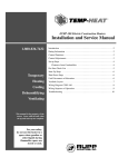
THP-750
Gas, Direct-Fired Temporary Heater
Installation and Service Manual
1-800-836-7432
Warning . . . . . . . . . . . . . . . . . . . . . . . . . . . . . . . . . . . . . . . . . . . . . . . . . . . . . .3
Introduction . . . . . . . . . . . . . . . . . . . . . . . . . . . . . . . . . . . . . . . . . . . . . . . . . . .4
Rating Information . . . . . . . . . . . . . . . . . . . . . . . . . . . . . . . . . . . . . . . . . . . . . .5
Control Functions . . . . . . . . . . . . . . . . . . . . . . . . . . . . . . . . . . . . . . . . . . . . . . .6
Fuel Supply System — Bulk-Tank System . . . . . . . . . . . . . . . . . . . . . . . . . . .7
Natural-Gas Installations . . . . . . . . . . . . . . . . . . . . . . . . . . . . . . . . . . . . . . . . .8
Set-Up . . . . . . . . . . . . . . . . . . . . . . . . . . . . . . . . . . . . . . . . . . . . . . . . . . . . . . .9
Preliminary Start-Up Steps . . . . . . . . . . . . . . . . . . . . . . . . . . . . . . . . . . . . . .10
Temporary
Control Vestibule Layout . . . . . . . . . . . . . . . . . . . . . . . . . . . . . . . . . . . . . . . .11
Start-Up Steps . . . . . . . . . . . . . . . . . . . . . . . . . . . . . . . . . . . . . . . . . . . . . . . .12
Heating
Cooling
Shut-Down Steps . . . . . . . . . . . . . . . . . . . . . . . . . . . . . . . . . . . . . . . . . . . . . .13
Short-Term . . . . . . . . . . . . . . . . . . . . . . . . . . . . . . . . . . . . . . . . . . . . . . . .13
Long-Term or Disconnect . . . . . . . . . . . . . . . . . . . . . . . . . . . . . . . . . . . . .13
Dehumidifying
Wiring Sequence of Operation . . . . . . . . . . . . . . . . . . . . . . . . . . . . . . . . . . . .14
Ventilating
Control Adjustments . . . . . . . . . . . . . . . . . . . . . . . . . . . . . . . . . . . . . . . . . . . .19
Troubleshooting . . . . . . . . . . . . . . . . . . . . . . . . . . . . . . . . . . . . . . . . . . . . . . .16
Ignition . . . . . . . . . . . . . . . . . . . . . . . . . . . . . . . . . . . . . . . . . . . . . . . . . . .19
Airflow Control . . . . . . . . . . . . . . . . . . . . . . . . . . . . . . . . . . . . . . . . . . . . .19
Setting Control . . . . . . . . . . . . . . . . . . . . . . . . . . . . . . . . . . . . . . . . . .19
This manual is the property of the
owner. Leave with the unit when
set-up and start-up are complete.
For your safety,
do not use this heater in a
space where gasoline or
other liquids having
flammable vapors are
stored or used.
To Check Setting . . . . . . . . . . . . . . . . . . . . . . . . . . . . . . . . . . . . . . . . .19
TEMP-HEAT ®
Warning
General Hazard Warning
Failure to comply with the precautions provided with this heater can result in death,
serious bodily injury and property loss or damage from hazards of fire, explosion,
burn, asphyxiation, carbon monoxide poisoning, and electrical shock.
Only persons who can understand and follow the instructions should use or service
this heater.
If you need assistance or heater information such as an instructions manual, labels,
etc., contact the manufacturer.
Warning
Fire, burn, inhalation and explosion hazard.
Keep solid combustibles, such as building materials, paper or cardboard, a safe
distance away from the heater as recommended by the instructions.
Never use the heater in spaces which do or may contain volatile or airborne
combustibles, or products such as gasoline, solvents, paint thinner, dust particles
or unknown chemicals.
Warning
Not for home or recreational vehicle use.
This heater is designed and approved for use as a construction heater under ANSI Z83.7-1990.
We cannot anticipate every use which may be made of our heaters. Check with your local fire safety
authority if you have questions about applications.
Other standards govern the use of fuel gases and heat-producing products in specific applications.
Your local authority can advise you about these.
3
Introduction
The following recommendations are not intended to supplement requirements of federal, state, or local
codes having jurisdiction over the application and operation of this heater.
This instruction booklet contains the necessary information, instructions, and guidelines to achieve
maximum efficiency and safety from the TEMP-HEAT construction heater. Please read all instructions
before attempting the set-up and operation of this heater.
The THP-Series Heaters are direct-fired, fresh-air heaters used to provide temporary heat for buildings
under construction, alteration, or repair. The area of fresh air required for safe operation must be equal to
the area of the unit’s intake grill. THP-Series heaters draw fresh, outside air through the unit’s intake
and discharge tempered air controlled by a remote thermostat. The heaters generate 85° F to 170° F
discharge temperatures with models ranging from 300,000 BTU/hour to 4,500,000 BTU/hour operating
on natural gas or propane gas vapor.
Equipment with these characteristics are preferred for enclosed areas because they generate lower moisture and contaminant levels while controlling ventilation and air distribution.
Most models are equipped with a remote thermostat and an adjustable, automatic burner control. This
combination prevents extreme temperature fluctuations that occur when ON/OFF burner controls are
selected.
THP-750 Installation and Service Manual
TEMP-HEAT ®
Rating Information
THP-750
For indoor or outdoor installation
Unit Specifications
CFM
BTU/Hour
Inlet Pressure
Natural Gas
Inlet Pressure
Propane
Electrical Requirements
minimum
maximum
minimum psig
maximum psig
minimum psig
maximum psig
voltage/hertz/phase/amps
4,000
43,200
750,000
1/2
4*
5
10
230/60/1/17.5
230/60/3/10
460/60/3/5
Dimensions
Weight
Minimum distance from
combustible materials
l x w x h, in
68 x 33 x 65
lbs
650
floor, in
0
top, in
6
sides, in
6
discharge, ft
10
Ambient Conditions
minimum F
-40
maximum F
120
* For inlet pressure over 4-psi natural gas, contact TEMP-HEAT.
5
Control Functions
Airflow Switch Verifies that proper airflow through unit is present before ignition can
take place.
First-Stage Regulator Reduces tank pressure to an intermediate pressure, and supplies inlet
pressure to a second-stage regulator.
Flame-Safety Control Senses flame and shuts down the heater in the event of flame failure.
High-Temperature Limit Opens electric circuit to flame-safety control and closes gas valves in the
event of an overheating condition.
Low-Temperature Limit Protects against the possibility of discharging freezing air into the
building in the event the burner fails to ignite. Pre-set at 40 F, this
control shuts the blower down if the temperature through the unit drops
below this setpoint.
Manual Gas Valve Manually shuts off fuel supply at heater. For short-term, shut-down
only.
Manual Bypass Switch Over-rides the automatic shut-down of the blower during start-up if the
temperature through the unit is below the 40 F setting of the LowTemperature Limit control.
Modulating Control Valve Regulates gas supply to the burner controlled by the remote thermostat.
Pilot Valve Supplies fuel to the ignition pilot when starting unit.
Second-Stage Regulator Reduces the outlet pressure from first-stage levels to burner pressure.
Starter Interlock Proves motor-starter is engaged in the normally closed position.
Thermostat Automatically cycles the heater from low- to high-fire to maintain
desired room temperature.
THP-750 Installation and Service Manual
TEMP-HEAT ®
Fuel Supply System — Bulk-Tank System
•
Installation must comply with all state and local codes or, in the absence of local codes, with the
standard for the Storage and Handling of Liquified Petroleum Gases, ANSI/NFPA 58.
•
Locate fuel tanks according to the minimum distances shown in the Rating Information
Table on page 5.
•
The vapor-supply fuel line from the tank or vaporizer must have a first-stage regulator located
at the tank or vaporizer to reduce the tank pressure to the 10-psi needed to supply unit.
•
A vaporizer may be necessary, especially on multiple-heater installations where adequate storage
supply is not attainable or practicable.
•
Vaporizers must be no closer than 10-ft from a container.
•
Locate vaporizers at a minimum of 15-ft from fuel-transfer valves.
Each Storage Capacity
above Ground
Minimum Distance
from Building
one, 500-gal tank
10-ft
one or two, 1000-gal tanks
25-ft
2001-gal or more
50-ft
union
hand valve
tee
tank fill
vapor service valve
POL connector NOTE: left-hand thread
first-stage regulator
reducer
union and UL approved 350 psi gas hose
to temporary heating unit when a vaporizer is not used
first-stage regulator
street elbow
elbow
gauge tee
tee
tee
globe valve
union
elbow
shut-off valve
reducer
Liquid inlet line to vaporizer
must be schedule 80 black iron pipe
or copper tubing of adequate size.
Contact state or local authorities governing
the installation of vaporizers.
dripleg
to temporary heating unit
Typical Vaporizer Installation — Algas 40/40 Vaporizer
7
Natural Gas Installations
•
See Rating Information Table on page 5 for proper inlet pressure.
•
Gas meter and supply system must be able to supply the minimum supply pressures as specified
in the Rating Information Table on page 5.
•
Follow all federal, state, and local codes governing temporary-gas connections.
•
Leak test all gas connections using a 1:3 solution of soap and water.
THP-750 Installation and Service Manual
TEMP-HEAT ®
Set-Up
•
Block heater’s wheels to prevent movement.
•
Keep fresh-air intake and heated-air discharge clear of obstruction.
•
Provide clearance to allow access to vestibule, blower, and motor compartments.
•
Heater must be level and in compliance with minimum-clearance and minimum-distance requirements for combustible materials. See Rating Information Table on page 5.
•
Position heater to draw 100% fresh outside air through its intake grill.
•
Do not use or operate the heater in the presence of combustible vapors of liquids.
•
Maintain a maximum voltage differential of plus or minus 10% while unit is running.
•
Protect the hose from traffic, building materials, and contact with hot surfaces both during use
and while in storage.
•
Do not move, handle, or service heater while hot, running, or connected to power supply.
•
Check for gas leaks and proper functioning during installation, periodically, or when relocating.
discharge-air
hood extension
regulator
manual shut-off valve
regulator
pressure gauge
from gas supply
pressure gauge
meter
Typical Heater Installation
9
Preliminary Start-Up Steps
•
Check for proper fuel-supply application, connections, and pressure.
•
Purge gas line of air, as necessary.
•
Leak test all gas connections with a 1:3 solution of soap and water.
•
Do not operate unit if leaks are present.
•
Determine that unit is drawing 100% fresh outside air through its intake grill.
•
Check for proper electrical connections and supply voltage.
•
Check that the intake and discharge of unit are free from obstructions.
•
Reset flame-safety control by pressing reset button on control.
•
Reset motor overload.
•
Check control settings:
high-temperature limit switch: 240° F
low-temperature limit switch:
40° F
low-temperature light
flame relay light
blower switch
burner switch
THP-750 Switch Panel
THP-750 Installation and Service Manual
TEMP-HEAT ®
Control Vestibule Layout
1
2
4
3
5
6
12
7
11
reset
10
9
8
THP-750 Vestibule Layout
Item Number
1
2
3
4
5
6
7
8
9
10
11
12
Description
ignition transformer
discharge temperature selector
amplifier
high-temperature limit switch
manual-reset, high-temperature limit switch
low-temperature limit switch
power transformer
flame-safety control
motor starter and motor-starter overload
24-V transformer
terminal strip
airflow switch
11
Start Up Steps
1. Connect power supply. See Rating Information Table on page 5 for electrical requirements.
2. Confirm heater is set up for fuel being supplied. See Rating Information Table on page 5 for proper
gas-inlet pressures.
3. Plug remote thermostat into thermostat jack on heater. Mount in an area away from the discharge-air
stream and set at highest setting.
4. Open fuel-supply valve at tank slowly.
5. Open manual gas valve at heater.
6. Reset Flame-Safety control.
7. Check control settings:
high-temperature limit switch: 240° F
low-temperature limit switch:
40° F
8. Turn main disconnect to the ON position.
9. Turn blower and burner switches to the ON position.
For units equipped with electronic low-temperature limit control:
allows unit to run for 3-min. If discharge-sensor bulb located in the discharge-air stream does
not reach the 40° F minimum temperature, the unit shuts down, and the low-temperature bulb
glows.
To reset: turn blower and burner switches OFF. Reset the Flame-Safety Control and turn
switches back to ON.
Do not attempt to light the pilot manually.
10. Observe flame at both high- and low-fire ranges.
High Fire
high-fire flame produces a discharge temperature approximating
160° F with flame extending 14-in beyond burner.
Low Fire
low-fire flame produces a discharge temperature between 85° and 90° F.
11. Set remote thermostat to the desired room temperature.
THP-750 Installation and Service Manual
TEMP-HEAT ®
Shut Down Steps
Short-Term Shut Down
•
Turn burner switch to OFF position.
•
Wait 30-sec.
•
Turn blower switch to OFF position.
•
Look to see that flame is extinguished.
Extended Shut-down or Disconnection of Unit
•
With unit running, close vapor-fuel supply valve at vaporizer.
Caution: Do not close liquid supply valve while vaporizer is ON. See vaporizer for proper
operation of vaporizer. Contact your gas company for further information on safe handling
of propane vaporizers.
•
Allow heater to run until flame-safety light goes ON, indicating that all gas has been burned
from gas lines.
Caution: Check to see that pilot light on vaporizer is extinguished before disconnecting gas lines.
•
Turn burner switch OFF.
•
Continue running blower until no flame exists in the base of the burner.
•
Turn the blower switch OFF.
•
Turn power OFF at source and disconnect electrical lines.
•
Disconnect propane-vapor line from heater.
•
Contact gas company to disconnect vaporizer.
13
Wiring Sequence of Operation
FU-01
L2
FU-01
L3
FU-01
MT-01
OL-01
ST-01
L1
230/460 VOLT
60 HERTZ
3 PHASE
POWER SUPPLY
BK
BK
BK
BK
BK
BK
BK BK
R
BK
ADD JUMPER FOR
SINGLE PHASE
FU-03
TR-01
BK
120V
FU-03
230/460V
BK
G
FU-03
W
SN-01
LI-01
W
R
O
OL-01
Y
BR
ST-01
Y
BR
W
W
SW-05
TS-07
O
R
BL
SW-07
ST-01
BK
BR
O
R
Y
BL
TS-05
TS-04
PS-01
BK
BL
BK
BR
SN-02
W
Y
BK
VA-02
W
Y
R
VA-01
BK
W
TR-03
VA-03
G
W
W
LI-02
RE-07
O
R
W
TR-02
120V
BK
W
BR
24V
Y
BL
AM-01
TS-08
R
G
Y
BL
R
O
BR
BK
VA-05
TS-11
TS-01
Component Identification
AM-01
FU-01
FU-02
LI-01
LI-02
MT-01
OL-01
PS-01
RE-07
SN-01
amplifier
main fuse
control fuse
low-temperature light
burner-reset light
supply-blower motor
starter overload
air-flow switch
flame-safety relay
low-temperature sensor
SN-02
ST-01
SW-05
SW-06
SW-07
SW-08
TR-02
TR-03
TS-01
flame rod
motor starter
blower switch
burner switch
blower-start switch
blower-stop switch
low-voltage transformer
ignition transformer
discharge-air sensor
THP-750 Installation and Service Manual
TS-04
TS-05
TS-07
TS-08
TS-11
VA-01
VA-02
VA-03
VA-05
high-temperature limit switch
cabinet high-temperature limit
low-temperature limit switch
remote-discharge temperature
room-override thermostat
main-gas valve
second main-gas valve
pilot-gas valve
modulating-gas valve
TEMP-HEAT ®
When the main safety switch, SW-01 is turned ON, power is supplied:
— to the line side of the motor starter, ST-01,
— to the primary side of the power transformer, TR-01, and
— from the secondary side of the power transformer to the FU-02 control fuse, located
on the transformer.
F2
to
1
Terminal 1 receives 120-V power from the FU-02 control fuse.
2
Terminal 2 is neutral.
1
to
3
Terminal 3 receives power from Terminal 1 through the blower switch, SW-07
or the blower auxillary switch SW-05.
3
to
5
Terminal 5 receives power from Terminal 3 through the low-temperature limit
control, TS-07.
Note: the low-temperature limit control is a timed thermostat that allows the heater
to run for 3-min. If the discharge sensor bulb, located in the discharge-air stream,
does not meet the 40° F minimum temperature setting of the control, the unit shuts
down and the low-temperature alarm light, LI-01, glows.
To Reset: turn blower switch OFF, wait 45-sec and turn back ON.
5
to
6
Terminal 6 receives power from Terminal 5 through the burner switch, SW-06.
6
to
7
Terminal 7 receives power from Terminal 6 through the supply-fan motor starter.
7
to
8
With proper air flow through unit, Terminal 7 supplies power to Terminal 8 through
the airflow switch, PS-01.
8
to
9
Terminal 9 receives power from Terminal 8 through the high-temperature limit
switch, TS-04.
9
to
10
Terminal 10 receives power from Terminal 9 through the cabinet high-temperature
switch, TS-05.
10
to
6
Terminal 10 supplies power to Terminal 6 within the flame-safety control,
RE-07. Internal circuitry energizes Terminal’s 4, 8, 9 and 10 within the control.
8
to
13
Terminal 8 of the flame-safety control supplies power to Terminal 13, energizing the
pilot-gas valve, VA-03 and the main-gas valve, VA-01.
Note: if pilot flame is not present, the flame-safety control locks out, and the control
must be reset.
10
to
12
Terminal 10 of the flame-safety control supplies power to Terminal 12, energizing the
ignition transformer, TR-03.
9
to
11
Terminal 9 of the flame-safety control supplies power to Terminal 11, energizing the
second-main gas valve, VA-02
15
Troubleshooting
Problem
Probable Cause
Remedy
Blower does not operate
Inadequate or no
voltage present
Check power supply to unit. 230- to 460-V must be
available. Check Rating Information Table on page 5.
Fuse loose or blown
Check control fuse, FU-02.
Blower switch not
in ON position
Turn ON.
Motor overload tripped
Reset.
Blower switch defective
With switch in the ON position, check for 115-V at
Terminal 3. Replace switch if voltage is not present.
Unit shuts down
on flame safety
Press reset button on control.
Low-temperature limit
Timer: 3-min
switch not at proper setting Temperature: 40 F
To Reset: turn burner and blower switches OFF and
then back ON.
Defective low- temperature Check wiring connections. Check for 115-V at
limit switch
Terminal 5. If no voltage is present, replace switch.
Blower runs, burner
does not ignite
Starter overload
defective
Replace.
Defective motor
Check wiring condition and connections from motor
starter to motor. If motor is receiving proper voltage and
wiring is in good condition, the motor is defective and
must be replaced.
Burner switch not
in ON position
Turn ON.
Defective burner switch
With burner switch in the ON position, check voltage at
Terminal 5. If 115-V are present at Terminal 5 and not
at Terminal 6, the burner switch is defective.
Insufficient airflow
Check unit's intake and discharge for obstructions.
Inspect fan blade and motor for proper operation.
Adjust airflow control according to the instructions on
page 19.
Remove airflow tubing and inspect for obstructions.
Reconnect tubing.
If voltage is present at Terminal 7 but not at Terminal 8,
replace the airflow switch.
High-temperature limit
switch out of adjustment
Press reset button on switch. If unit continues to shut
down, the unit is either overfired, or the limit switch is
defective. Contact TEMP-HEAT.
Adjustable hightemperature limit switch
not at proper setting
Set at 240 F. If unit continues to shut down, the unit is
either overfired or the limit switch is defective. Contact
TEMP-HEAT.
THP-750 Installation and Service Manual
TEMP-HEAT ®
Problem
Probable Cause
Remedy
Blower runs, burner
does not ignite
Flame-safety control
lockout
Press reset on control. If resetting does not correct
problem, replace flame safety control.
Gas valve defective
Check wiring connections and condition to and from gas
valves. If wiring is in good condition and voltage is
present, the valves may need replacement.
Fuel supply
Confirm gas supply to unit. See Rating Information
Table on page 5 for inlet gas supply pressures.
Bleed air from gas hose.
Ignition spark rod
improperly gapped
Maintain 1/8-in gap as shown on page 19.
Replace spark rod as needed.
Spark rod defective
Turn blower and burner switches OFF. Check spark-rod
gap and condition. Carefully inspect porcelain insulator
for cracks or moisture. Replace if necessary.
Insufficient airflow
Check unit's intake and discharge for obstructions.
Inspect fan blade and motor for proper operation.
Adjust airflow control according to the instructions on
page 19.
Remove airflow tubing and inspect for obstructions.
Reconnect tubing.
If voltage is present at Terminal 7 but not at Terminal 8,
replace the airflow switch.
Fuel supply
Confirm gas supply to unit. See Rating Information
Table on page 5 for inlet gas supply pressure.
Remote thermostat
Plug remote thermostat securely into thermostat jack on
heater. Set at a temperature higher than the indoor-air
temperature.
Burner ignites, does
not stay lit
Blower runs, burner
ignites, but unit does
not deliver high fire
17
Control Adjustments
Ignition
1. Clean and dry electrodes.
2. Check porcelain insulators for cracks or
moisture. Replace if necessary.
3. Adjust as shown.
4. Secure ignition leads.
5. Replace spark electrode if defective.
Ignition Assembly
Air-Flow Control
adjusting screw
Setting control
1. Turn ON/OFF switch to ON.
2. With unit operating at high-fire, turn
adjusting screw clockwise until burner
goes OFF.
3. Turn adjusting screw counter-clockwise
1/2 turn at a time until burner re-ignites.
To check setting
1. Set remote thermostat on highest setting.
2. Observe that when operating on high-fire,
the switch does not break contact.
THP-750 Installation and Service Manual
airflow tube connections
Airflow Control
TEMP-HEAT ®
19
Boston, MA
Chicago, IL
Cleveland, OH
Columbus, OH
Denver, CO
Detroit, MI
Duluth, MN
Minneapolis, MN
Newark, DE
Watertown, WI
800-666-8133
800-283-2843
800-443-3301
800-444-3481
800-577-7053
800-678-1488
888-539-5438
800-836-7432
800-232-7419
800-558-9209
fax 508-624-0036
fax 847-931-7704
fax 330-721-7742
fax 614-471-1933
fax 303-783-8579
fax 248-526-9527
fax 218-722-6701
fax 612-707-5104
fax 302-369-8022
fax 920-261-4523
RUPP Industries manufactures, sells and rents commercial, industrial
and construction equipment. Our employees — our most valuable
asset, are dedicated to finding innovative solutions that fulfill our
customers’ product and service requirements.
One Rupp Plaza
3700 West Preserve Boulevard
Burnsville, Minnesota 55337-7746
1-800-836-7432
0123.9901
© RUPP Industries, Inc. 1999
Printed in USA