1
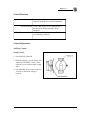
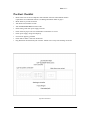
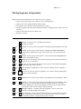
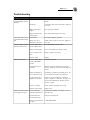
ETHP-100 Electric Construction Heaters
Installation and Service Manual
1-800-836-7432
Introduction . . . . . . . . . . . . . . . . . . . . . . . . . . . . . . . . . . . . . . . . . . . . . . . . . . .2
Rating Information . . . . . . . . . . . . . . . . . . . . . . . . . . . . . . . . . . . . . . . . . . . . . .2
Control Functions . . . . . . . . . . . . . . . . . . . . . . . . . . . . . . . . . . . . . . . . . . . . . . .3
Control Adjustments . . . . . . . . . . . . . . . . . . . . . . . . . . . . . . . . . . . . . . . . . . . . .3
Set-up Steps . . . . . . . . . . . . . . . . . . . . . . . . . . . . . . . . . . . . . . . . . . . . . . . . . . .4
Clearance from Combustibles . . . . . . . . . . . . . . . . . . . . . . . . . . . . . . . . . .4
Pre-Start Check List . . . . . . . . . . . . . . . . . . . . . . . . . . . . . . . . . . . . . . . . . . . . .5
Start-Up Steps . . . . . . . . . . . . . . . . . . . . . . . . . . . . . . . . . . . . . . . . . . . . . . . . .6
Temporary
Shut-Down Steps . . . . . . . . . . . . . . . . . . . . . . . . . . . . . . . . . . . . . . . . . . . . . . .6
Unit Disconnect or Relocation . . . . . . . . . . . . . . . . . . . . . . . . . . . . . . . . . . . . .6
Heating
Cooling
Dehumidifying
Ventilating
This manual is the property of the
owner. Leave with the unit when
set-up and start-up are complete.
For your safety,
do not use this heater in a
space where gasoline or
other liquids having
flammable vapors are
stored or used.
Vestibule Layout . . . . . . . . . . . . . . . . . . . . . . . . . . . . . . . . . . . . . . . . . . . . . . . .7
Wiring Diagram ETHP-100 . . . . . . . . . . . . . . . . . . . . . . . . . . . . . . . . . . . . . . .8
Wiring Sequence of Operation . . . . . . . . . . . . . . . . . . . . . . . . . . . . . . . . . . . . .9
Troubleshooting . . . . . . . . . . . . . . . . . . . . . . . . . . . . . . . . . . . . . . . . . . . . . . .10
Introduction
The RUPP Model ETHP-100 Electric Construction Heaters are temporary electric heaters for use in nonhazardous locations. The unit may be installed indoors or out, and used to bring in 100% outdoor air, or
heat and re-circulate building air.
The control system is intended for space-heating applications. A room sensor is supplied as the main
control. There is a second discharge-temperature control which overrides the room control if the room
control attempts to drive the discharge temperature too high.
Both controllers modulate heat output on proportional cycle-time output generated by the controller. At
low-temperature output, the controller is ON for a small portion of the cycle, 0.10 second in a 1.0 second
cycle. At higher temperature output, the controller output stays ON for a longer portion of the cycle.
For example, if the controller calls for 80% output, the discharge controller runs for 0.80 second during
every 1.0 second cycle. This type of control provides smooth and continuous control of the heater from
zero to 100% output, and can be optimized for use with generators as well as with permanent power
systems. Coils are energized through solid state Silicone Controlled Rectifier relays, SCR, allowing
rapid cycle times without the worry of relay-contract burnout.
Rating Information
Unit Specifications
ETHP-100
CFM
Electrical Requirements
Coil Specifications
Ambient Temperature
Temperature Control Range*
2,100
voltage
amps
phase
hertz
kW
460 +/- 10%
150
3***
60
100
voltage
kW
control
element type
maximum temperature rise
maximum discharge-air temperature
480
10
SCR
fin tubular
120o F
180o F
operating
storage
-10o to 130 o F
-10o to 150 o F
digital space-temperature control
digital discharge-override control
50o to 90 o F
50o to 190o F
1 x w x h (inches)
59 x 26 x 49
floor (inches)
top (inches)
sides (inches)
discharge (feet)
6
6
6
15
(lbs)
650
Motor Horsepower
Dimensions
Minimum distance from
combustible materials
Weight
1
*Based on digital-space
control with digital-discharge
temperature.
***Phase imbalance +/- 3%
ETHP-100 Installation and Service Manual
2
TEMP-HEAT ®
Control Functions
Thermostat Senses room temperature and adjusts heater
output to maintain desired room temperature.
Air-Flow Switch Verifies that proper air flow through unit is
present before heating elements can be
energized.
High-Temperature Limit Shuts power off at unit's main circuit breaker in
an overheating condition.
Control Adjustments
Air-Flow Control
Setting Control
1. Turn ON/OFF switch ON.
2. With unit operating, check voltage with
voltmeter at Terminals 2 and 6. Turn
adjusting screw clockwise until voltage
drops.
3. Turn adjusting screw counter-clockwise
1/2 turn at a time until voltage is
restored.
Airflow Control
ETHP-100 Installation and Service Manual
3
TEMP-HEAT ®
Pre-Start Checklist
•
Heater must be level and in compliance with minimum clearance and minimum distance
requirements for combustible material. See Rating Information Table on page 2.
•
Block wheels to prevent movement.
•
Turn heater-circuit breaker to OFF.
•
Turn OFF-BLOWER-HEAT switch to OFF.
•
Install wiring cable from power supply to heater.
•
Check cable for proper wire size and that these connections are secure.
•
Check power supply voltage and ampacity.
•
Unit must be properly grounded.
•
Check that air intake is free from obstruction.
•
Plug thermostat into thermostat jack on heater. Mount in area away from discharge-air stream.
Typical Switch Panel
ETHP-100 Installation and Service Manual
5
TEMP-HEAT ®
Set-Up Steps
Positioning
•
Installation must comply with all federal, state and local codes.
•
Heater must be level and in compliance and minimum distance requirements for combustible
material.
•
Block wheels to prevent movement.
•
Locate heater away from general traffic while allowing ample area for inspection and service.
•
The inlet and discharge of the unit must be kept free of obstacles. The intake air will draw paper and
other debris to it which interferes with the unit’s operation.
•
Select an area that provides good air circulation and even heat distribution to the area being heated.
Clearance from Combustibles
The discharge temperature of these units may reach 180o F for standard unit and 250o F for high static
unit. Maintain minimum distance from combustible materials as follows:
sides: 6 inches
top: 6 inches
bottom: 6 inches
discharge: 15 feet
ETHP-100 Installation and Service Manual
4
TEMP-HEAT ®
Vestibule Layout
Item Number
Description
1
heating elements
2
air-flow sitch
3
solid-state electric contactors
4
solenoid contactors
5
fuse block
6
motor starter
7
fuse block
8
motor
9
high-temperature limit
10
safety-disconnect
11
transformer
12
terminal strip
13
cam-locR
ETHP-100 Installation and Service Manual
7
TEMP-HEAT ®
Start-Up Steps
1. Turn power ON at source. If ground alarm light comes on, check that unit is properly grounded. If
light continues to glow after unit has been properly grounded, see the Troubleshooting section on
page 10.
2. Check voltage with voltmeter. A minimum of 90% of the rated voltage must be present. Do not
operate the unit if voltage difference between phases exceeds 3%. Correct power supply or wiring to
unit. See Rating Information Table on page 2.
3. Do not operate unit while doors are open or access panels are missing.
4. Turn main heater-circuit breaker ON. Discharge-controller and room-controller displays turn ON.
5. Turn OFF-BLOWER-HEAT switch briefly to the BLOWER position, then back to OFF.
6. Observe blower rotation as blower stops. If rotation is incorrect, turn power OFF and reverse any
two (2) power supply leads and recheck rotation direction.
7. Set room controller at desired room temperature.
8. Plug thermostat into thermostat jack on heater.
9. Set discharge controller at 180o F.
To set controller: Press and hold the * key, set temperature using the arrow up/down keys. See
illustration on page 8.
10. Turn OFF-BLOWER-HEAT switch to HEAT position. The blower will start, and the electric coils
will run at full output until the discharge sensor or room-temperature controller reaches its set-point.
11. Set OFF-BLOWER-HEAT switch for desired operation.
12. To ensure maximum heating capacity, set Discharge Temperature Controller at 180o F.
13. Set Room Temperature Controller at desired room temperature.
Shut-Down Steps
1. Turn OFF-BLOWER-HEAT switch to BLOWER position.
2. Allow blower to run for several minutes to cool the coil element and casing before turning OFFBLOWER-HEAT switch to OFF.
3. Turn unit circuit breaker to OFF.
Unit Disconnect or Relocation
1. Turn main power supply OFF.
2. Disconnect power supply cables from unit.
3. Disconect room thermostat.
4. Secure doors and access panels before moving.
ETHP-100 Installation and Service Manual
6
TEMP-HEAT ®
Wiring Sequence of Operation
When the Main Circuit Breaker CB-01 is turned ON, power is supplied::
— to the line side of the Electric Coil Contactors, AC-01 through AC-03;
— to the line side of the Supply Fan Motor Starter, MT-01;
— to the primary side of the Control Voltage Transformer, TR-01;
— from the secondary side of the Control Voltage Transformer, through the Control Fuse, FU-02 to
Terminal 1;
— to the line side of the motor saver, MS-01, and,
— Terminal 2 is neutral.
1
Terminal 1 provides power to the Motor Saver, MS-01.
2
Terminal 2 is neutral.
Terminal 11 receives power from Terminal 1 through the ground-fault protector, MS01.
1
to
11
11
to
4
Terminal 4 receives power from Terminal 11 through the OFF-BLOWER-HEAT
switch, SW-02 completing the circuit to the blower-motor starter, which starts the
blower.
11
to
5
Terminal 5 receives power from Terminal 11 only when the OFF-BLOWER-HEAT
switch is in the HEAT position.
5
to
6
With proper air flow through unit, Terminal 5 supplies power to Terminal 6 through
the low air flow switch, PS-01.
6
to
7
If proper air flow is present, Terminal 7 receives power from Terminal 6 through the
blower-motor starter interlock, ST-01.
6
to
6a
When discharge air temperature is below set-point on TS-05, power is supplied to
Terminal 7.
7
AC-01
to AC-02 To AC-01, AC-02 & AC-03 Power supplied to coil contactor allowing main heating
circuits to become energized.
AC-03
7
to
8
Terminal 8 receives power from Terminal 7 through Silicon-Controlled Relay, SR-02.
8
to
9
Terminal 9 receives power from Terminal 8 through Silicon-Controlled Relay, SR-01.
These relays cycle ON and OFF controlled by the PID controllers. If either the
discharge temperature or the room temperature reach the set point of the controller,
the controller reduces the heat output to maintain setpoint.
11
to
PID Both PID controllers - discharge and room temperature - receive power from
Terminal 11 through the Motor Saver, MS-01.
9
to
CO When Terminal 9 is energized, solid-state contactors, CO-01 through CO-03 provide
power to the heating coil elements. The solid-state contactors cycle in accordance
with the PID controllers, varying the heat output of the unit.
ETHP-100 Installation and Service Manual
9
TEMP-HEAT ®
Troubleshooting
Problem
Probable Cause
Remedy
Unit will not start.
Controller display does not
illuminate
No power to unit
Check Voltage at main supply power and circuit
breaker.
Blown fuse
Check Motor and control-circuit fuses. Replace if
necessary.
Main circuit breaker
tripped
Reset main Circuit breaker.
High-temperature limit
switch tripped
Reset limit and determine cause of trip.
Unit will not start. Green
ground-fault indicator light
ON
Ground fault
Unit must be properly grounded.
Motor saver out of
adjustment or defective
Adjust voltage trip level to 180 volts. Replace if
necessary.
Controller display working
and bower will not start
OFF-BLOWER-HEAT
switch in OFF position
Select BLOWER or HEAT position.
Motor overload tripped
Reset overload and check voltage at motor.
Loose or broken belt or
drive
Repair or replace as necessary.
Defective motor
Replace.
OFF-BLOWER-HEAT
switch in BLOWER
position
Select HEAT position.
Room thermostat not
cancelled
Plug thermostat into thermostat jack on heater
securely. Mount in area away from discharge-air
stream.
Setting on discharge or
room controller too low
Set discharge controller at maximum 180o F. Set
room controller at desired room temperature.
Air-flow switch out of
adjustment or defective
Check for air-flow obstructions. Check belt
tension. Adjust for 1" deflection. See page 3 for
air-flow switch adjustments. Replace air-flow
switch if required.
Defective controller
Check controller and replace if necessary.
Defective silicon relays
Replace relay.
Room or discharge
controller improperly set
Set discharge controller at maximum 180o F for
high static unit
Room thermostat is
located in warm area
Relocate room thermostat.
Heater not properly sized
for space
Contact TEMP-HEAT.
Blower runs, no heat
Blower runs, unit heats but
not enough to heat space
9
Boston, MA
Chicago, IL
Cleveland, OH
Columbus, OH
Denver, CO
Detroit, MI
Duluth, MN
Minneapolis, MN
Newark, DE
Watertown, WI
800-666-8133
800-283-2843
800-443-3301
800-444-3481
800-577-7053
800-678-1488
888-539-5438
800-836-7432
800-232-7419
800-558-9209
fax 508-624-0036
fax 847-931-7704
fax 330-721-7742
fax 614-471-1933
fax 303-783-8579
fax 248-526-9527
fax 218-722-6701
fax 612-707-5104
fax 302-369-8022
fax 920-261-4523
RUPP Industries, Inc. manufactures, sells and rents commercial,
industrial and construction equipment. Our employees — our most
valuable asset, are dedicated to finding innovative solutions that
fulfill our customers’ product and service requirements.
One Rupp Plaza
3700 West Preserve Boulevard
Burnsville, Minnesota 55337-7746
1-800-836-7432