1
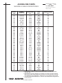
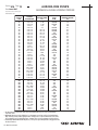
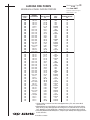
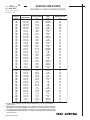
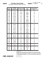
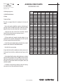
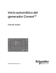
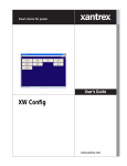
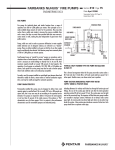
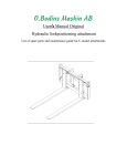
AURORA MODELS 481-483-485
ENGINEERING SPECIFICATIONS
CENTRIFUGAL FIRE PUMPS
Furnish and install where shown on plans__________________
Aurora Fire Pump System(s) complete with pump, driver, controller and
accessories. The pumping unit shall be listed by Underwriters' Laboratories,
Inc. and/or shall be fully approved by the Associated Factory Mutual Fire
Insurance Companies, where applicable. The pumping unit shall meet all
requirements of the National Fire Protection Association Pamphlet No.20. The
Fire Pump shall be designed to deliver__________________G.P.M.
when operating at__________________PSIG. The pump shall also
deliver not less than 150% of rated capacity at a pressure not less than 65%
of rated pressure. The shut off pressure shall not exceed 140% of rated
pressure. Suction pressure is__________________PSIG. The pump
shall
operate
at
a
maximum
synchronous
speed
of__________________ R.P.M.
The Fire Pump shall be (one of the following):
Pentair Water
Section 910 Page
Date April 2003
61
Supersedes Section 910 Page 61
Dated June 1994
(A) AURORA MODEL 481 HORIZONTAL BASE MOUNTED size ____-481____ horizontal split case, bronze fitted, SINGLE STAGE, double suction
centrifugal pump.
(B) AURORA MODEL 485 HORIZONTAL BASE MOUNTED size ____-485____ horizontal split case, bronze fitted, TWO STAGE, single suction,
centrifugal pump.
The driver shall be a horizontal, foot mounted, open drip-proof (or T.E.F.C.),
ball bearing type, AC, induction, squirrel cage motor: wound for ____ volts,
3 phase, 60 (50) Hertz. The motor shall be of such capacity that 115% of the
full-load ampere rating shall not be exceeded at any condition of pump load.
Locked rotor current shall not exceed the values specified in NFPA Pamphlet
No.20.
Section 910 Page
Date April 2003
62
Supersedes Section 910 Page 62
Dated June 1994
AURORA MODELS 481-483-485
ENGINEERING SPECIFICATIONS
CENTRIFUGAL FIRE PUMPS
Pump and motor shall be mounted on a common baseplate of steel (or
optional with drip rim). Pump and motor shall be checked for alignment after
the pump base has been installed and grouted in place.
C. AURORA MODEL 483 VERTICAL BASE MOUNTED size ____-483-____
vertical splitcase, vertical mounted, bronze fitted, SINGLE STAGE double
suction, centrifugal pump.
The driver shall be a vertical, open drip-proof (or T.E.F.C.), ball bearing type,
AC, induction, squirrel cage "P" face motor: wound for ____ volts, 3 phase,
60 (50) Hertz. The motor shall be of such capacity that 115% of the full-load
ampere rating shall not be exceeded at any condition of pump load.
Locked rotor current shall not exceed the values specified in NFPA Pamphlet
No.20.
The mounting feet of the pump shall be machined perpendicular to the shaft.
The pump shall be bolted to an extra heavy cast iron drip rim ring base. The
top of the pump shall be machined to receive the motor mounting bracket.
The mounting bracket shall be machined with registered fits to align pump
and motor.
Casings shall be of cast iron having a minimum tensile strength of 35,000
P.S.I. Bearing housing supports, and suction and discharge flanges shall be
integrally cast with the lower half of the casing. Removal of the upper half of
the casing must allow the rotating element to be removed without
disconnecting the suction and discharge flanges.
Impellers shall be of the enclosed type and shall be of vacuum cast bronze.
Impellers shall be dynamically balanced, keyed to the shaft, and held in place
with threaded shaft sleeves.
The pump shaft shall be made of SAE 1045 Steel or equal, accurately
machined to give a true running rotating element. Shaft shall be protected by
bronze sleeves which are key locked and threaded so that the sleeves
tighten with the rotation of the shaft. An o-ring shall seal between the
impeller hub and the shaft sleeve to protect the pump shaft.
Pump shall be equipped with renewable bronze casing rings so designed that
hydraulic pressure will seat them against a shoulder in the pump case around
the full periphery of the wearing ring. The wearing rings will be locked by
dowelling to prevent rotation. The rotating element uses heavy duty grease
lubricated ball bearings and shall be equipped with water slingers. Bearing
housings shall be so designed to flush lubricant through the bearing.
All pumps where the suction pressure is expected to average 40 P .S.I. or
below, shall be provided with a lantern ring connected to the pressure side of
the pump by a cored passage in the parting flange of the pump. Stuffing
boxes shall be equipped with split bronze packing glands designed for easy
removal for packing inspection and maintenance.
The fire pump unit shall include the following accessories, as required by
NFPA standards (depending on the conditions under which the pumps are to
be installed).
1.
Flow metering device
_____
2.
Eccentric tapered suction reducer
_____
3.
Concentric tapered discharge increaser
_____
4.
Discharge tee
_____
5.
Base elbow
_____
6.
Hose valves
_____
7.
Caps and chains
_____
8.
Hose valve header
_____
9.
Blind flange
_____
10. Pressure gauges
X
_____
11. Main relief valve (mandatory for engine drives)
_____
12. Circulation relief valve
X
_____
13. Relief cone - enclosed (mandatory for engine drives)
_____
14. Automatic air release valve
X
_____
15. Splash shield (electric drive only)
_____
16. Balldrip valve
_____
17. Coupling guard
X
_____
Pentair Water
AURORA MODELS 481-483-485
ENGINEERING SPECIFICATIONS
CENTRIFUGAL FIRE PUMPS
The Fire Pump motor control shall be U .L. Listed and/ or F.M. Approved, where
applicable. It shall be completely assembled, wired and tested by the control
manufacturer before shipment from the factory, and shall be labeled "Fire Pump
Controller." The controller shall be located as close as practical and within sight of
the motor. The controller shall be so located or protected that it will not be injured
by water escaping from the pump or connections. The controller shall be of the
combined manual and automatic, (across-the-line) (primary resistor) (partwind)
(limited service) (wye delta) type, and shall be complete with:
1. Disconnect switch - externally operable, quick-break type.
Section 910 Page
Date April 2003
63
Supersedes Section 910 Page 63
Dated October 1983
than____degrees F.
The engine shall be of the self-contained open type mounted on a suitable
base with the following minimum accessories, plus any others that may be
necessary by local requirements.
1. Dual battery set sized to NFPA Pamphlet No.20 requirements with
X
electrolyte shipped in separate containers, rack and cables
_____
2. Dual battery charger of proper type for batteries used (included in U.L.
X
Listed/F.M. Approved controller)
_____
2. Circuit breaker - time delay type with trips in all phases set for 300% of
the motor full-load current. The interrupting capacity of circuit breaker shall
be____asymmetrical amperes.
X
3. Electric starter with suitable generator and voltage regulator _____
4. Engine water pump
X
_____
3. Motor starter - across-the-line type capable of being energized
automatically through the pressure switch or manually by means of an
externally operable handle.
5. Heat exchanger cooling system
X
_____
6. Water cooled or ceramic blanketed exhaust manifold
X
_____
4. Pressure switch set to cut in at____p.s.i.g. and out at____p.s.i.g.
7. Lubricating oil pump and filter
X
_____
5. Running period timer - set to keep motor in operation, when started
automatically, for a minimum period of one minute for each 10 HP motor
rating, but not to exceed 7 minutes.
8. Speed governor
X
_____
9. Fuel injection system
X
_____
6. Pilot lamp - to indicate circuit breaker closed and power available.
10. Air cleaner
X
_____
7. Ammeter test link and voltmeter test studs.
11. Stubshaft
X
_____
8. Alarm relay - to energize an audible or visible alarm through an
independent source of power to indicate circuit breaker open or power failure.
12. Fuel Pump
X
_____
13. Engine Jacket Pre-heater
X
_____
14. Oil Emersion Heater
X
_____
9. Manual selection station - a two position station shall be provided on the
enclosure marked " Automatic" and "Non-automatic."
10. Means shall be provided on the Controller to operate an alarm signal
continuously while the pump is running.
15. Proper instrument panel complete with engine run warning light, water
temperature gauge, oil pressure gauge, ammeter, totalizing type tachometer
X
and hour meter
_____
Control equipment shall meet all requirements of NFPA No.20.
16. Commercial Grade Muffler
X
_____
17. Cooling water line for the engine heat exchanger assembly
X
_____
18. Flexible exhaust connectors
X
_____
ENGINE DRIVE
The Fire Pump shall be driven by a U .L. Listed and F.M. Approved diesel
engine. The engine shall conform to the requirements of NFPA Pamphlet
No.20 and be approved for Fire Pump use. The rated speed shall not exceed
____RPM and shall develop ____ H.P. to drive the pump. Reserve H.P.
shall be as stipulated in Pamphlet No.20 when the unit is operating
at____ft. above sea level in an ambient temperature not greater
Pentair Water
All engine wiring for automatic operation shall terminate in a proper junction
box to permit field connection to a separate control panel.
Section 910 Page
Date April 2003
64
AURORA MODELS 481-483-485
Supersedes Section 910 Page 64
Dated October 1983
ENGINEERING SPECIFICATIONS
CENTRIFUGAL FIRE PUMPS
FUEL SYSTEM
A suitable fuel system for the diesel engine shall be furnished. It must be in
accordance with NFPA Pamphlet No.20, and shall include a____gallon
above surface storage tank. Flexible fuel connectors, combination vent-flash
arrestor and fill cap shall be included.
Starting the engine by a fire alarm relay, deluge valve relay, or remote pushbutton station shall be included in the controller circuit.
In the event the pump, engine and control are in an unattended area, a
remote alarm panel shall be furnished as per NFPA Pamphlet No.20.
TESTS
AUTOMATIC ENGINE CONTROL PANEL
The automatic engine control panel shall be approved for fire pump service
and shall meet the requirements of NFPA Pamphlet No. 20. The panel shall
be of the floor-mounted type, and enclosed in a moisture and dust tight
housing. A combination manual and automatic type controller with "ManualOff-Automatic" selector switch shall be provided also, a 115 volt single phase
power failure relay or a pressure switch, which will (when the system drops
to ____psig) activate all electrical circuits to automatically start the engine.
Should the engine fail to start after the required cranking cycles, the
controller shall disconnect the starting circuit and activate an alarm system
using lights and buzzer or bell. "Low oil pressure" and "high jacket-water
temperature" shall also be indicated by a suitable alarm system. The engine
shall not shut down if either of these conditions occurs during an operating
cycle.
The engine shall be started automatically by the controller at least once a
week and operate a minimum of 30 minutes. An appropriate timing
arrangement shall determine the day and hour of this test.
The pump and electric motor (or engine) shall be thoroughly shop-tested by
the respective manufacturers as required by NFPA Pamphlet No.20. The
control panel shall also be tested as a unit. All such tests shall be conducted
prior to shipment.
The pump, driver, controller and all accessories shall be purchased under a
unit contract. The pump shall be given a complete performance test with
POSITIVE SUCTION PRESSURE. A certified performance curve shall be
prepared and submitted. Pumps shall also be hydrostatically tested to twice
the shut off pressure, but in no case less than 250 lbs. per sq. inch.
In the case of diesel drives, the pump manufacturer shall perform a second
pump operational test as a unit with the job engine. Test data shall be
furnished.
The pump manufacturer shall assume unit responsibility and shall provide the
services a factory trained representative to supervise and/or be available to
conduct final field acceptance tests.
Pentair Water
AURORA FIRE PUMPS
MAXIMUM ALLOWABLE WORKING PRESSURE
Section 910 Page
Date June 2007
71
Supersedes Section 910 Page 71
Dated June 2002
RATED
CAPACITY
G.P.M.
250
250
250
250
250
250
250
250
250
250
500
500
500
500
500
500
500
500
500
500
500
500
500
500
500
500
500
500
500
500
500
500
500
500
500
500
500
500
500
500
500
750
750
750
750
750
750
750
AP MODEL
DESIGNATIONS
2.5-481-10B
2.5-483-10B
2.5-481-10B
2.5-483-10B
3-481-10
3-481-10/DI
3-483-10
3-481-10
3-481-10/DI
3-483-10
3-481-10
3-483-10
3-481-10/DI
3-491-9A
3-491-9A
3-491-9C
3-492-10A
4-481-11A
4-483-11A
4-481-11C
4-483-11C
4-481-11C/DI
4-481-11C
4-481-11C/DI
4-481-11D
4-483-11D
4-481-15
4-483-15
4-485-15
4-492-10
4-492-14
4-492-18
5-485-12
5-485-12
5-485-12
5-485-15
6-491-12A
6-491-12A
6-491-12A
6-491-12A
6-491-12A
4-481-11A
4-483-11A
4-481-11C/DI
4-481-11C
4-481-11C
4-483-11C
4-481-11C/DI
RATED HEAD
PRESSURE RANGE
P.S.I.
51-115
51-115
52-167
52-167
40-120
40-120
40-120
40-100
40-100
40-100
50-150
50-150
50-150
46 - 101
55 - 125
95 - 140
125 - 165
40-55
40-55
55-134
55-134
55-134
75-180
75-180
61-138
61-138
60-80
60-80
150-210
110 - 170
45 - 75
76 - 125
182-319
188-330
228-476
68-144
97 - 140
149 - 164
157 - 190
163 - 233
191 - 278
40-50
40-50
66-164
66-164
65-192
65-192
65-192
APPROXIMATE
SPEED
R.P.M.
2950/3000
2950
3550/3560
3560
2950/3000
2950/3000
2950
3550/3560
3550/3560
3560
3550/3560
3560
3550/3560
3000
3300
3550/3560
3550/3560
1750/1770
1770
2950/3000
2950
2950/3000
3300
3300
2950/3000
2950/3000
1750/1770
1770
1750/1770
3550/3560
1750/1770
1750/1770
2950
3000
3560
1460/1480
2600
2800
2950/3000
3300
3550/3560
1750/1770
1770
3300
3300
3550/3560
3560
3550/3560
MAXIMUM ALLOWABLE
WORKING PRESSIRE
P.S.I.
250
250
250
250
210
450
210
210
450
210
210
210
450
588
588
588
254
270
270
275
275
500
275
500
275
275
200
200
270
436
175
175
625
625
625
270
425
425
425
425
425
270
270
500
275
275
275
500
1. The data shown above is listed in the current Fire Protection Equipment Directory of U.L. and is consistent with the
requirements of F.M.
2. Maximum Working Pressure (PSI) is defined by U.L. as the maximum pressure that can be developed at the discharge
flange under any operating condition. Applications where working pressures exceed these limits must be referred to the
factory. Maximum pressure at the discharge flange = maximum suction pressure plus maximum total developed head.
3. In determining “Maximum Allowable Working Pressure”, both agencies require initial hydrostatic testing approval at twice
the values shown above.
Pentair Water
DI = Ductile Iron construction
Section 910 Page
Date June 2007
72
AURORA FIRE PUMPS
MAXIMUM ALLOWABLE WORKING PRESSURE
Supersedes Section 910 Page 72
Dated October 2005
RATED
CAPACITY
G.P.M.
750
750
750
750
750
750
750
750
750
750
750
750
750
750
750
750
750
750
750
750
750
750
750
750
750
750
750
750
750
750
750
750
750
750
750
1000
1000
1000
1000
1000
1000
1000
1000
1000
1000
1000
1000
1000
1000
1000
1000
1000
1000
1000
AP MODEL
DESIGNATIONS
4-481-15
4-481-11D
4-483-11D
4-483-15
4-491-11A
4-491-11A
4-491-11A
4-491-11A
4-491-11A
4-491-11C
4-491-11C
4-491-14C
4-491-14C
4-491-14C
4-491-8A
4-492-18
5-481-11C
5-483-11C
5-481-11C/DI
5-481-15
5-483-15
5-491-18A
5-491-18A
5-491-18A
6-485-12
6-485-12
6-485-12
6-485-17A
6-485-17A/DI
6-485-17A
6-485-17A/DI
6-491-12A
6-491-12A
6-491-12A
6-491-12A
4-491-14C
4-491-14C
4-491-14C
5-481-11B
5-481-11B/DI
5-481-11B
5-483-11B
5-481-11B/DI
5-481-11C
5-481-11C/DI
5-481-11C
5-483-11C
5-481-11C/DI
5-481-11C
5-483-11C
5-481-11C/DI
5-481-15
5-483-15
5-481-17
RATED HEAD
PRESSURE RANGE
P.S.I.
71-95
81-190
81-190
71-95
225
100 - 143
100 - 150
100 - 185
144 - 221
140 - 175
145 - 200
55 - 90
60 - 130
75 - 160
67 - 78
100 - 125
105-154
105-154
105-154
50-70
50-70
115 - 240
90 - 140
95 - 200
197-340
205-352
310-506
80-175
80-175
140-245
140-245
132 - 148
142 - 175
147 - 218
180 - 266
95
100 - 120
95 - 150
145-165
145-165
165-200
165-200
165-200
90-135
90-135
97-146
97-146
97-146
90-160
90-160
90-160
50-90
50-90
90-125
APPROXIMATE
SPEED
R.P.M.
1750/1770
3550/3560
3550/3560
1770
3550/3560
3550/3560
2950/3000
3300
3550/3560
3300
3550/3560
1750/1770
2100
2300
2950/3000
1750/1770
2950/3000
2950
2950/3000
1750/1770
1770
2300
1750/1770
2100
2950
3000
3560
1460/1480
1460/1480
1750/1770
1750/1770
2800
2950/3000
3300
3550/3560
2100
2100
2300
3300
3300
3550/3560
3560
3550/3560
3300
3300
2950/3000
2950
2950/3000
3550/3560
3560
3550/3560
1750/1770
1770
1750/1770
MAXIMUM ALLOWABLE
WORKING PRESSIRE
P.S.I.
200
275
275
200
363
363
363
363
363
363
363
396
396
396
225
175
325
325
450
210
210
345
345
345
625
625
625
330
400
330
400
425
425
425
425
396
396
396
325
450
325
325
450
325
450
325
325
450
325
325
450
210
210
210
1. The data shown above is listed in the current Fire Protection Equipment Directory of U.L. and is consistent with the
requirements of F.M.
2. Maximum Working Pressure (PSI) is defined by U.L. as the maximum pressure that can be developed at the discharge
flange under any operating condition. Applications where working pressures exceed these limits must be referred to the
factory. Maximum pressure at the discharge flange = maximum suction pressure plus maximum total developed head.
3. In determining “Maximum Allowable Working Pressure”, both agencies require initial hydrostatic testing approval at twice
the values shown above.
DI = Ductile Iron construction
Pentair Water
AURORA FIRE PUMPS
MAXIMUM ALLOWABLE WORKING PRESSURE
Section 910 Page
Date June 2007
73
Supersedes Section 910 Page 73
Dated February 1, 2005
RATED
CAPACITY
G.P.M.
1000
1000
1000
1000
1000
1000
1000
1000
1000
1000
1000
1000
1000
1000
1000
1000
1000
1000
1000
1000
1000
1000
1000
1250
1250
1250
1250
1250
1250
1250
1250
1250
1250
1250
1250
1250
1250
1250
1250
1250
1250
1250
1250
1250
1250
1250
1250
1250
1250
1250
1250
1250
1250
1250
1250
1250
1250
AP MODEL
DESIGNATIONS
5-483-17
5-491-14A
5-491-18A
5-491-18A
5-491-18A
5-492-10
6-481-11
6-481-11HH
6-481-11HH
6-481-11HH
6-481-11HH
6-481-14HH
6-481-14HH
6-481-14HH
6-481-14HH
6-481-14HH
6-481-14HH
6-481-18C
6-481-18C/DI
6-483-11
6-483-18C
6-485-17A
6-485-17A/DI
4-491-14C
4-491-14C
4-491-14C
4-491-14C
5-491-18A
5-491-18A
6-481-11HH
6-481-11HH
6-481-11HH
6-481-11HH
6-481-14HH
6-481-14HH
6-481-14HH
6-481-14HH
6-481-14HH
6-481-14HH
6-481-15
6-483-15
6-481-18B
6-483-18B
6-481-18B/DI
6-481-18C
6-483-18C
6-481-18C/DI
6-481-18C
6-483-18C
6-481-18C/DI
6-481-20
6-483-20
6-481-20/DI
8-481-12
8-483-12
8-481-21
8-481-21
RATED HEAD
PRESSURE RANGE
P.S.I.
90-125
75 - 125
110 - 240
85 - 135
90 - 200
85 - 120
40-50
69-115
93-155
74-186
188-219
77-133
96-160
75-203
102-287
130-248
154-287
81-108
81-108
40-50
81-108
130-240
130-240
116 - 147
155 - 230
64 - 84
94 - 121
119 - 134
119 - 193
96-110
98-151
111-182
132-216
94-130
87-156
122-301
110-287
122-247
145-287
55-96
55-96
100-140
100-140
100-140
78-105
78-105
78-105
81-108
81-108
81-108
84-168
84-168
84-168
43-52
43-52
90-142
136-200
APPROXIMATE
SPEED
R.P.M.
1770
2100
2300
1750
2100
2950/3000
1750/1770
2600
2950/3000
3300
3550/3560
2100
2300
2600
2950/3000
3300
3550/3560
1460/1480
1460/1480
1770
1480
1750/1770
1770
2300
2500
1750/1770
2100
1750/1770
2100
2600
2950/3000
3300
3550/3560
2100
2300
2600
2950/3000
3300
3550/3560
1750/1770
1770
1750/1770
1770
1750/1770
1750/1770
1770
1750/1770
1460/1480
1480
1460/1480
1750/1770
1770
1750/1770
1750/1770
1770
1750/1770
1750/1770
MAXIMUM ALLOWABLE
WORKING PRESSIRE
P.S.I.
210
396
345
345
345
436
200
500
500
500
500
500
500
500
500
500
500
325
450
200
325
330
400
396
396
396
396
345
345
500
500
500
500
500
500
500
500
500
500
230
230
225
225
450
325
325
450
325
325
450
230
230
450
200
200
325
325
1. The data shown above is listed in the current Fire Protection Equipment Directory of U.L. and is consistent with the
requirements of F.M.
2. Maximum Working Pressure (PSI) is defined by U.L. as the maximum pressure that can be developed at the discharge
flange under any operating condition. Applications where working pressures exceed these limits must be referred to the
factory. Maximum pressure at the discharge flange = maximum suction pressure plus maximum total developed head.
3. In determining “Maximum Allowable Working Pressure”, both agencies require initial hydrostatic testing approval at twice
the values shown above.
Pentair Water
DI = Ductile Iron construction
Section 910 Page
Date June 2007
74
AURORA FIRE PUMPS
MAXIMUM ALLOWABLE WORKING PRESSURE
Supersedes Section 910 Page 74
Dated February 1, 2005
RATED
CAPACITY
G.P.M.
1500
1500
1500
1500
1500
1500
1500
1500
1500
1500
1500
1500
1500
1500
1500
1500
1500
1500
1500
1500
1500
1500
1500
1500
1500
1500
1500
1500
1500
1500
1500
1500
1500
2000
2000
2000
2000
2000
2000
2000
2000
2000
2000
2000
2000
2000
2000
2000
2000
2000
2000
2000
2000
2000
2000
AP MODEL
DESIGNATIONS
5-481-11D
6-481-11HH
6-481-11HH
6-481-14HH
6-481-14HH
6-481-14HH
6-481-14HH
6-481-15
6-483-15
6-481-18B
6-483-18B
6-481-18B/DI
6-481-18C
6-483-18C
6-481-18C/DI
6-481-20
6-483-20
6-481-20/DI
6-492-10
6-492-10
6-492-10U
6-491-14C
6-491-14C
6-491-14C
6-491-14C
6-491-14A
6-491-14A
6-492-15
6-492-18
8-481-12
8-481-21
8-481-21
8-483-12
6-481-15B
6-481-20/DI
6-481-15B
6-481-18C
6-483-15B
6-481-18C/DI
6-481-20
6-483-18C
6-483-20
6-491-14A
6-491-14A
6-491-18C
6-491-19A
6-491-19A
6-491-19A
8-481-17B
8-483-17B
8-481-17B
8-483-17B
8-481-21
8-481-21
8-492-15
RATED HEAD
PRESSURE RANGE
P.S.I.
90-120
121-144
142-209
142-196
153-285
137-240
158-283
50-90
50-90
95-134
95-134
95-134
75-102
75-102
75-102
80-165
80-165
80-165
95-135
100 - 175
82 - 115
88-151
85-125
90-100
76-86
99-164
95-135
70-90
90 - 145
40-50
88-141
135-200
40-50
80-100
123-150
100-125
100-140
80-100
100-140
123-150
100-140
123-150
90 - 125
90 - 150
105 - 170
210
115 - 155
135 - 200
52-94
52-94
53-127
53-127
82-135
130-195
63 - 87
APPROXIMATE
SPEED
R.P.M.
3300
2950/3000
3550/3560
2600
2950/3000
3300
3550/3560
1750/1770
1770
1750/1770
1770
1750/1770
1460/1480
1480
1460/1480
1750/1770
1770
1750/1770
3300
3550/3560
2950/3000
2300
2100
1900
1750/1770
2300
2100
1750/1770
1750/1770
1750/1770
1460/1480
1750/1770
1770
1750/1770
1750/1770
2100
1750/1770
1770
1750/1770
1750/1770
1770
1770
2100
2300
2100
2200
1750/1770
2100
1460/1480
1480
1750/1770
1770
1460/1480
1750/1770
1750/1770
MAXIMUM ALLOWABLE
WORKING PRESSIRE
P.S.I.
250
500
500
500
500
500
500
230
230
225
225
450
325
325
450
230
230
450
440
440
440
482
482
482
482
478
478
191
200
200
325
325
200
200
450
200
225
200
450
230
225
230
482
482
362
332
332
332
208
208
208
208
325
325
194
1. The data shown above is listed in the current Fire Protection Equipment Directory of U.L. and is consistent with the
requirements of F.M.
2. Maximum Working Pressure (PSI) is defined by U.L. as the maximum pressure that can be developed at the discharge
flange under any operating condition. Applications where working pressures exceed these limits must be referred to the
factory. Maximum pressure at the discharge flange = maximum suction pressure plus maximum total developed head.
3. In determining “Maximum Allowable Working Pressure”, both agencies require initial hydrostatic testing approval at twice
the values shown above.
DI = Ductile Iron construction
Pentair Water
Section 910 Page
Date June 2007
AURORA FIRE PUMPS
74.1
MAXIMUM ALLOWABLE WORKING PRESSURE
RATED
CAPACITY
G.P.M.
2500
2500
2500
2500
2500
2500
2500
2500
2500
2500
2500
2500
2500
2500
2500
3000
3000
3000
3000
3000
3000
3000
3000
3000
3000
3000
3000
3500
3500
3500
3500
3500
4000
4000
4000
4000
4000
4000
4500
4500
4500
5000
5000
5000
5000
5000
AP MODEL
DESIGNATIONS
8-481-17B
8-483-17B
8-481-17B
8-481-21A
8-481-21A
8-491-14A
8-491-14A
8-491-14A
8-491-14A
8-491-14A
8-491-14A
8-491-18A
8-492-19
10-481-18
10-481-18D
8-491-14A
8-491-14A
8-491-18A
8-491-18A
8-491-18A
8-491-18A
10-481-15C
10-481-18
10-481-18
10-481-18D
10-481-18D
10-492-18
10-481-18
10-481-18
10-481-18D
10-481-18D
10-492-18
10-481-18
10-481-18D
10-481-18D
10-491-20
10-491-20
12-481-18A
10-481-18D
10-491-20
10-491-20
10-481-18D
10-491-20
10-491-20
10-491-20
10-491-20
RATED HEAD
PRESSURE RANGE
P.S.I.
75-130
75-130
115-144
100-125
123-190
50
125 - 135
55 - 75
75 - 85
90 - 115
90 - 120
135
90 - 125
65-100
63-96
60 - 80
95 - 115
130
104 - 115
120 - 125
130 - 165
100-110
61-99
99-145
61-95
90-138
94 - 151
60-97
98-140
59-94
88-135
100 - 153
95-100
64-92
85-134
94 - 98
110 - 225
67-102
81-132
90 - 195
106 - 223
91-130
88 - 109
110 - 195
110 - 221
102 - 109
APPROXIMATE
SPEED
R.P.M.
1750/1770
1770
2100
1460/1480
1750/1770
1750/1770
2300
1750/1770
2100
2100
2300
1750/1770
1750/1770
1460/1480
1460/1480
1750/1770
2100
1750/1770
1750/1770
1750/1770
2100
2300
1460/1480
1460/1480
1460/1480
1750/1770
1750/1770
1460/1480
1750/1770
1460/1480
1750/1770
1750/1770
1750/1770
1460/1480
1750/1770
1750/1770
1900
1460/1480
1750/1770
1750/1770
1900
1750/1770
1750/1770
1750/1770
1900
1900
MAXIMUM ALLOWABLE
WORKING PRESSIRE
P.S.I.
208
208
208
325
325
321
321
321
321
321
321
330
184
200
237
321
321
330
330
330
330
200
200
200
237
237
185
200
200
237
237
185
200
237
237
335
335
200
237
335
335
237
335
335
335
335
1. The data shown above is listed in the current Fire Protection Equipment Directory of U.L. and is consistent with the
requirements of F.M.
2. Maximum Working Pressure (PSI) is defined by U.L. as the maximum pressure that can be developed at the discharge
flange under any operating condition. Applications where working pressures exceed these limits must be referred to the
factory. Maximum pressure at the discharge flange = maximum suction pressure plus maximum total developed head.
3. In determining “Maximum Allowable Working Pressure”, both agencies require initial hydrostatic testing approval at twice
the values shown above.
Pentair Water
DI = Ductile Iron construction
Section 910 Page
Date June 2007
74.2
THIS PAGE LEFT INTENTIONALLY BLANK
Section 910 Page
Date April 2003
AURORA FIRE PUMPS
ENGINEERING DATA
75
Supersedes Section 910 Page 75
Dated March 1982
FIRE PUMPS
Fire pumps for industrial plants and similar locations have a range of
capacities from 500 to 4,500 gallons per minute. Their principal use is to
make available large amounts of water for fire protection. They may take
suction from a public main simply to increase the pressure available from
such a source, but they are more often provided with their own reservoirs,
suction tanks or wells, making the plant independent of piped water from
public systems.
Pumps, which are used to make up pressure deficiencies in water supplies
(which otherwise are of adequate volume), are referred to as "booster"
pumps. These are often installed in a by-pass so that the city or other supply
may be used directly when desired. Such booster pumps have commonly been
of 500 to 1,000 gallons per minute capacity.
Small pumps known as "special fire service" pumps are sometimes used in
situations where a limited amount of water is available (as from a city main)
and it is necessary to avoid drafting too heavily from it. At zero lift, their
maximum capacity should not exceed 130 percent of rated capacity .The
capacities of such pumps are ordinarily 150, 200, 300 or 450 gallons per
minute. Such special fire service pumps may also be used as booster pumps
where local conditions make such small pumps acceptable.
Currently, most fire pumps installed are centrifugal types because these lend
themselves readily to electric; steam turbine or internal combustion engine
drive, and may be readily arranged for automatic operation.
PUMP CHARACTERISTICS
Permanently installed fire pumps may be designed to deliver their rated
capacity against a specified head. This is usually 231 feet or l00 pounds per
square inch, but in any case may be set according to the expected service
demands. Fire pumps are required to deliver 150 percent of rated capacity at
not less than 65 percent of the rated pressure. This produces a "flat"
characteristic curve for these pumps. This is in contrast to the performance
characteristics used for automobile pumpers and industrial pumps.
Pentair Water
(1) UL Listed Only
REMOVABLE PANEL
SCREEN RAISED
HIGH WATER
LOWEST STANDING
WATER LEVEL
BOTTOM OF
RESERVOIR
STRAINER
RACK
SCREENS
YARD
SYSTEM
VERTICAL SHAFT TURBINE-TYPE FIRE PUMP INSTALLATION
IN WET PIT
This is favored arrangement when the fire pump must take suction under a
lift. Trash rack has 1/2-inch flat or 3/4-inch round steel bars spaced 2 to 3
inches apart. Double screens, one shown raised, one in position.
PUMP SUCTION (HORIZONTAL PUMP WITH WATER
SUPPLY UNDER A POSITIVE HEAD)
Including allowance for velocity and friction loss through all suction pipe and
fittings, the size of the suction pipe shall be such that the total equivalent
operating suction lift will not exceed 15 feet. The suction pipe must be tight
and not be excessively long. The inspector will find that many pump troubles
are traceable to improper suctions. Workmen do not always make suction
pipes tight. An uneven grade may leave high spots where an air pocket may
break the suction. A long suction pipe introduces excessive friction loss. Each
pump should have a separate suction pipe.
Section 910 Page
Date April 2003
76
AURORA FIRE PUMPS
ENGINEERING DATA
Supersedes Section 910 Page 76
Dated March 1982
PRIMING
The suction pipe and pump casing must be full of water for the pump to work.
The pump casing must be provided with an automatic air release valve or
umbrella cock to allow evacuation of air.
1
4
6
3
2
7
5
8
9
10
14
11
13
17
B. Inspect the pump house or pump room. Note combustible construction
or any storage of combustible materials in the pump room. Consider the
location of pump house or pump room noting if it might
be made inaccessible or the power supplies made unreliable by a fire or by
flood waters. Determine adequacy of pump room ventilation to help prevent
dampness.
C. Note size and type of pump and arrangement of control devices. Note
size of suction and discharge connections and pipes. Give length of suction
pipe and the head in feet under which water is received by
the pump, or the lift in feet.
6
16
18
12
D. Ask for any records kept of weekly running tests made both to check
operation of the pump and the operation of manual and automatic starting,
stopping and general control equipment provided as part of the installation.
See the results of the last annual full capacity test.
18
15
ARRANGEMENT OF CENTRIFUGAL FIRE PUMP WITH WATER
ALWAYS UNDER A HEAD
1. Aboveground suction tank. 2. Entrance elbow and square vortex plate, 4
by 4 feet, 4 inches above bottom of tank. 3. Suction pipe. 4. Frostproof
casing. 5. Flexible couplings. 6. Valves, indicating type. 7. Eccentric reducer.
8. Suction gage. 9. Horizontal fire pump. 10. Umbrella cock or automatic air
release. 11. Discharge gage. 12. Reducing tee. 13. Discharge check valve.
14. Relief valve, if required. 15. Discharge pipe. 16. Drain valve or ball drip.
17. Hose valve manifold with hose valves. 18. Pipe supports.
INSPECTION OF FIRE PUMPS
A. Trace water from its source to the pump. Water meters on supplies from
mains should not be type with excessive friction loss. Meters, or any fish traps
with them, should not be obstructed. Wells on vertical pumps should be
straight and of adequate diameter. Suction pipe from a large uncovered
reservoir, or from a pond or river supply, should get only
water free from sediment and foreign material. Examine screens at intakes
and inquire what arrangements are for their periodic cleaning.
E. Fire pumps are designed for relatively infrequent use, but must be able
to perform satisfactorily even after standing idle for some time. Note whether
the conditions generally make this possible. The pump should not be used for
any other pumping service. It should be possible for an excited and perhaps
unskilled person to start the pump. Note the extent to which employees show
familiarity with the operation of the pump.
CENTRIFUGAL FIRE PUMPS
Following are some of the important features to cover in an inspection.
There are many other details and for these consult CENTRIFUGAL FIRE PUMPS,
NFPA No.20, which covers the common method of driving; electric motors,
steam turbines, gasoline (installations prior to adoption of 1974 edition of
NFPA No.20) and diesel engines.
In general, pump and driver should be provided as a unit together with all
needed control equipment. There should be acceptable evidence available for
the inspector that the entire assembly is properly designed, such as listing of
the assembly by Underwriters’ Laboratories, Inc.. Underwriters’ Laboratories
of Canada or Factory Mutual Research Corporation.
CENTRIFUGAL FIRE PUMP INSTALLATIONS
PUMP SIZE, GPM
SIZE OF DISCHARGE PUMP, INCH (MIN)
SIZE OF SUCTION PUMP, INCH (MIN)
SIZE OF RELIEF VALVE, INCH
NUMBER OF HOSE VALVES
500
5
5
3
2
750
6
6
4
3
1,000
6
8
4
4
1,500
8
8
6
6
2,000
10
10
6
6
2,500
10
10
6
8
3,000
12
12
8
12
3,500
12
12
8
12
4,000
12
14
8
16
Pentair Water
4,500
14
16
8
16
Section 910 Page
Date April 2003
AURORA FIRE PUMPS
ENGINEERING DATA
77
Supersedes Section 910 Page 77
Dated March 1982
A. Check manufacturer’s head-delivery, efficiency and brake horsepower
curves against the conditions of service to determine general suitability of the
pump.
D. Look for suitable disconnecting means for electric circuits and proper
overcurrent protection. Inspect the transformer installation.
VENT
HAND PUMP
FOR FILLING
GRAVITY TANK
END OF PIPE
C. Investigate reliability of the electric power supply. There should be at
least one reliable source from stations not subject to fire damage and
preferably two independent circuits to the pump house. Underground circuits
are best, but in any case arrangements should be such that possible
interruptions by fire, wind or high water are minimized.
2-QUART
GRAVITY TANK
12 FT MINIMUM
B. Note nameplate data on electric motors to determine suitability.
12"
ELEVATION
OF ENGINE
FUEl PUMP
3/8"
SUCTION
PIPES
IN TANK
FILL
PIPE
F. Location of control equipment should be within sight of the pump.
Electrical apparatus should be protected against leakage from the pump and
other moisture. Control equipment should be in cabinets. Backs of cabinets
should be easily accessible.
G. Investigate the steam supply to turbines driving pumps.
H. If internal combustion engine drive is provided, investigate ventilation
of the pump room. Gasoline engines should not be installed in depressed
pump rooms where gasoline vapors, which are heavier than air, may
accumulate. Inspect the storage of main supply of gasoline or oil fuel. Ask if
gasoline supply is fresh -not more than a year old. Note if exhaust pipe is run
to a safe place outside. Flexible connection in exhaust pipe at engine should
allow for pipe expansion. Storage batteries should be properly maintained
and necessary spare parts kept on hand.
1-1/2"
1/2"
OVERFLOW
PIPE
VENT
STRAINER
TO
CARBURETOR
ENGINE
PUMP
CARBURETOR MUST BE ABOVE
HIGHEST LIQUID LEVEL IN
GASOLINE STORAGE TANK
CHECK VALVE
STORAGE
TANK
2" FILL PIPE
E. Examine starting and stopping and general control arrangements. Note
whether manual, or combined automatic and manual. Where a motor driven
centrifugal pump is the sole sprinkler supply, record any central station
supervisory service providing positive indications at the central station that
the pump has operated normally.
3 FT MINIMUM
STICK
GAUGE
ELEVATION OF ENGINE
FUEL PUMP NOT TO BE
OVER 6 FT ABOVE BOTTOM
OF GASOLINE STORAGE TANK
GASOLINE ENGINE FUEL SYSTEM
Schematic diagram of suitable pump feed for fuel. The valve in the line
from the 2-quart tank to the carburetor is normally kept closed.
up at all times. Turbines may require pressures 40 to 70 pounds. Very high
pressures are not desirable and superheated steam should not be used on
reciprocating type pumps. In general, reducing valves should be avoided, but
see NATIONAL STANDARD STEAM FIRE PUMPS, NFPA
No.21, for description of an arrangement which may be used for the fire
pump supply when steam with high superheat is the supply normally
available.
C. Investigate reliability of supply of water for boiler feed, which should be
separate from the main water supply when possible.
D. Investigate dependability of fuel supplies to boilers, noting total amount
stored on the premises. Minimum storage should be about 48 hours supply.
STEAM SUPPLIES FOR PUMPS
A. Note location of boiler house or boiler room. It should be cut off from
remainder of property and from probable interference by fire. The location
should be above high flood water .
B. Note number and horsepower of boilers. There should be a minimum of
two boilers providing steam for fire pumps. Horsepower of boilers on which
steam is regularly maintained should be sufficient to
operate all fire pumps to capacity.
For reciprocating steam pumps the boiler should be able to keep 50 pounds
Pentair Water
E. Steam piping in the boiler house should be so arranged that anyone or
all boilers may be reserved for steam pump supply only.
F. Steam line to the pumps should be an independent line from header on
the boiler. The main should run to the pump as directly as possible. If
there are two fire pump lines, each should have a valve at the boiler and
pump. Throttle valve should be of globe pattern.
G. Investigate possibility of steam main or mains being broken by falling
walls or burning buildings. Mains should be installed to take care of
expansion and contraction and be provided with proper traps.
Section 910 Page
Date April 2003
78
AURORA FIRE PUMPS
ENGINEERING DATA
Supersedes Section 910 Page 78
Dated March 1982
H. Valves in steam lines should be open and steam should be up to the
throttle valves on the pumps.
H. If pump is arranged for automatic as well as manual starting, have the
pump started by opening a test connection.
2. TESTS OF FIRE PUMPS
ELECTRICALLY DRIVEN CENTRIFUGAL PUMPS
In even a brief or routine inspection the inspector should request that pumps
be operated a few minutes at rated speed with water discharging through
some convenient opening. Steam reciprocating pumps may run until water is
discharging freely through the relief valve. The management of a property
with a fire pump should make similar running tests weekly. It
should have employees to make tests for the inspector. The inspector should
not operate equipment.
Electric pump controllers may have detailed instructions given on the
controller and these should be followed. Manual starting should be repeated
a number of times at each set.
On acceptance and at annual intervals, the pump should be given a complete
test. The annual tests are set up to provide a complete check on the
performance of the whole assembly: suction connections, pump, prime
mover, steam and electric supplies. In making such tests, several lines of 21/2” hose, 50 to 200 feet long, are laid out from hydrants or from the pump
manifold. Water is pumped and discharged through the hose lines, the
amount being calculated from pitot tube gage reading at the nozzles.
Inspectors should insist that nozzles be lashed at some convenient location to
make the work of testing easier and avoid injuries to men holding nozzles.
CENTRIFUGAL PUMPS
A. Determine that pump is primed and casing is full of water. Interior
wearing rings may be damaged by operation without water.
B. Have the pump started” observing proper method of starting for various
types of drive.
C. Observe bearings for signs of overheating.
D. Observe alignment of pump and driver. Note tightness of foundation
bolts.
STEAM TURBINE DRIVEN PUMP
A. To start pump, have steam admitted slowly at first to permit warming
up of turbine casing before allowing full head of steam on turbine.
B. If pop safety valve on casing blows, have steam shut off and examine
exhaust piping for closed valve or obstructed portion of piping.
C. Observe that governors maintaIn proper speed. Have the emergency
governor valve tested by tripping it.
D. To vary speeds below rated speeds, have main throttle valve used.
INTERNAL COMBUSTION ENGINE DRIVEN PUMP.
To start pump, follow manufacturer’s instructions as to starters.
FIRE PUMP START-UP AND FIELD ACCEPTANCE TEST
The following is a general outline for starting and field testing Fire Pump
Systems. It is understood that requirements and methods vary depending on
the location (city). Anyone becoming involved In fire pump sales, must fully
understand all local requirements, within his designated territory, the NFPA20 Pamphlet and the Factory Mutual Fire Protection Manual. A general
method to follow is outlined below.
E. Observe stuffing boxes of pump. With water seal supplied with water” a
small leak at stuffing box glands is necessary.
I. Be specific and complete when ordering Fire Pumps and accessories so that
the necessary and correct items can be supplied.
F. Watch pressure gages. Signs of suction leaks may be indicated by
flickering of gages or knocking in pump. Gage readings also may suggest that
there are obstructions in the suction line” such as ice” or that screens are
clogged, that well supply is inadequate” or that intakes are insufficiently
immersed.
2. Trouble can not be tolerated on the day of the field acceptance test,
therefore
G. Have all outlets closed, including relief valve, and note that pump shuts
off at the proper pressure (for horizontal shaft pumps usually not over 120
percent of rated pressure; for vertical shaft pumps 140 percent)
A. Visit the jobsite after the equipment has been delivered and check for
completeness and correctness and answer any questions the contractor may
have.
B. Visit the jobsite after installation and check for correctness of
installation.
Pentair Water
AURORA FIRE PUMPS
ENGINEERING DATA
Section 910 Page
Date April 2003
79
Supersedes Section 910 Page 79
Dated March 1982
3. After the installation is complete and the Fire Pump System is pressurized
and checked by the contractor” an initial test should be conducted. This is
to check the controller and motor. The test should be conducted (with
contractor present if possible on engine drive systems, engine
representative will be present for start-up) as follows:
C. Tachometer.
D. Pitot tube and gauge.
E. *Calibrated suction and discharge gauges with a range accuracy of
1/4%. (First three items are in your APCO-MATIC kit)
A. Close all valves on discharge outlets. Check pump and motor alignment.
B. Open suction valve.
C. Check motor controller service manual and perform any necessary steps
outlined, in the manual, prior to putting controller into operation. Also, read
manual to understand how to operate the controller. Set controller to manual
position.
*The gauges furnished with the pump are 3% accurate and could lead to
problems if used for the field acceptance test. Equipment which is necessary
for the test and should be supplied by the local authorities:
1) 50 ft. of 2-1/2' hose for each hose connection on the outside hose
header.
2) Play pipe with 1-3/4" nozzle for each hose.
D. With controller in manual position, the pump can be started. Check
relief valves, be sure they are not completely closed. Start pump.
E. Adjust packing (if necessary), note if pump bearings are heating
excessively; check pump RPM.
F. Completely close all relief valves. Check shut-off pressure of pump and
see if the total dynamic head agrees with factory certified head/capacity
curve.
G. Stop pump.
6. Field acceptance tests will vary in all locations. The following steps are
general and for electric drives. You will have to add any other requirements
which might be particular to your territory:
A. Hose and play pipe should be connected to each opening of outside hose
header.
B. Close discharge valve leading to building fire system.
C. Open discharge valve leading to outside hose header.
H. The jockey pump should be on line and proper system pressure
maintained.
D. Suction valve should be open.
E. Close all relief valves.
I. Set the motor controller to the automatic position.
F. Open one (1) outside hose valve.
J. Drop system pressure to below normal with test valve. The fire pump
should start automatically.
4. After all is checked and equipment is operating properly arrangements can
be made to perform the field acceptance test. People required to be present
and forms necessary for recording the test can be obtained from the local
insurance authorities.
5. Equipment necessary for field testing varies considerably in different
localities. The maximum that you, as a supplier of the fire pump, should
supply is:
G. Using pitot tube and gauge with 1-3/4" nozzle, valve should be
adjusted until gauge on pitot tube reads 30 PSI, this is equal to 500 GPM.
By opening additional valves and measuring the flow to equal 500 GPM, the
proper flow (500, 1000, 1500, 2000, 2500, 3000, 3500, 4000 or 4500) can
be obtained. Chart 1 lists nozzle pressures and flows for various nozzle sizes.
H. Open the necessary hose valves to obtain the rated flow. Check all
nozzles making sure the correct flow is maintained. Changing one valve
usually changes the flow in the other hoses. When the proper flow is assured,
check and record the following data:
A. Calibrated ammeter.
1) Suction gauge pressure.
B. Volt meter.
Pentair Water
Section 910 Page
Date April 2003
80
AURORA FIRE PUMPS
ENGINEERING DATA
Supersedes Section 913 Page 80
Dated March 1982
2) Discharge gauge pressure.
3) Check RPM with tachometer.
4) Voltage.
5) Amps (on all legs).
The panels are equipped with jacks for connecting the volt meter and
ammeter.
I. Return to the nozzles and check flow to make sure it did not change. If
any change is noted, re-establish the proper flow, recheck and record data.
Repeat this until you are sure all necessary data is correct and recorded.
J. Adjust hose valves until a flow of 150% of rated flow is obtained.
Proceed as before and record necessary data. Again, accuracy is
very, very important and necessary.
K. This step applies only if required by the local authorities. It is not
required by U.L. but is required by F .M. Open all hose valves full or just short
of extreme cavitation by the pump. Record all data.
L. Close all hose valves completely. Make sure all relief valves are closed.
Check and record all data at this shutoff (0 GPM) condition.
M. Set relief valves to proper setting.
I) System relief valve should be set slightly over maximum system pressure.
2) Casing relief valve should be set slightly under shutoff pressure of the
pump.
NOZZLE
PRESS.
10
20
30
35
40
45
50
55
60
62
64
66
68
70
72
74
76
78
80
85
90
95
100
105
110
115
120
1-1/8
l00
160
206
222
238
252
266
279
291
296
301
305
310
315
319
323
328
332
336
347
357
366
376
385
394
403
412
GPM AT VARIOUS NOZZLE SIZES
1-1/4
1-3/8
1-1/2 1-5/8
130
160
195
235
203
245
290
348
254
308
366
430
275
332
395
464
294
355
423
496
311
377
448
525
328
397
473
555
344
417
496
582
360
435
518
608
366
442
526
618
371
449
535
628
377
456
543
637
383
463
551
647
388
470
559
656
394
477
567
666
399
483
575
675
405
490
583
684
410
496
590
693
415
502
598
702
428
518
616
723
440
533
634
744
452
547
651
765
464
562
668
784
476
575
685
804
487
589
701
823
498
602
717
841
509
615
732
859
Q. Data obtained should match the certified performance test from the
factory (at 0 GPM, rate GPM, and 150% rated GPM). Average value of the
highest amps recorded should not exceed the nameplate amps of motor by
more than 115% (due to normal variations of test equipment, 120% may be
considered acceptable).
R. If data does not agree with test, recheck your data and if necessary,
retest pump. Be sure you figure total dynamic head correctly.
(1) UL Listed Only
Pentair Water
1-3/4
285
410
498
538
575
610
643
675
705
716
728
739
750
761
772
783
793
803
814
839
863
887
910
932
954
976
997