1
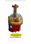
SNORK SERVICE MANUAL Table of Contents Introduction .................................................................................................................................... 1 1. Brief Description......................................................................................................................... 2 2. Caution ........................................................................................................................................ 2 2-1.Notice for Installation ........................................................................................................... 2 2-2. Notice for Operation ............................................................................................................ 2 3. Accessories ................................................................................................................................... 3 4. How to Play ................................................................................................................................. 3 5. Technical Parameter................................................................................................................... 5 6. Appearance.................................................................................................................................. 6 7. All Parts Description and Location ........................................................................................... 7 7-1. Rear View of Cabinet Assembly: ........................................................................................ 7 7-2. Instruction for Up-Down and Left-Right-Center Detect: ................................................ 9 8. The Structure of All Parts ........................................................................................................ 10 9. Marquee Installation Guide..................................................................................................... 17 10. Component .............................................................................................................................. 19 10-1. Counter [Meter] Board ................................................................................................... 19 10-2. Power Supply Input Panel .............................................................................................. 20 10-3. Coin Selector .................................................................................................................... 20 10-3-1. Mechanical Coin Selector......................................................................................... 20 10-3-2. Electronic Coin Selector ........................................................................................... 22 11. Troubleshooting ...................................................................................................................... 23 11-1. Error Codes ...................................................................................................................... 24 11-2. Common Problems .......................................................................................................... 25 12. Appendix.................................................................................................................................. 26 12-1. PIN Connection on Main Board [Ver: 03] ..................................................................... 26 12-2. Function & Testing Standard [Ver: 03] ......................................................................... 30 SNORK Introduction INTRODUCTION 1. This appliance is not intended for use by persons (including children) with reduced physical, sensory or mental capabilities, or lack of experience and knowledge, unless they have been given supervision or instruction concerning use of the appliance by a person responsible for their safety. 2. Children should be supervised to ensure that they do not play with the appliance. 3. Correct Disposal of this product: This marking indicates that this product should not be disposed with other household wastes throughout the EU. To prevent possible harm to the environment or human health from uncontrolled waste disposal, recycle it responsibly to promote the sustainable reuse of material resources. To return your used device, please use the return and collection systems or contact the retailer where the product was purchased. They can take this product for environmental safe recycling. 1 SNORK 1. Brief Description “Snork” [TW.JQ01.29] is a coin-operated, self-merchandising candy and/or prize vending game machine developed by designers of our company. The game “Snork” utilizes a reliable vacuum pick up system which is controlled by the Player to retrieve candy and/or prizes such as small toys or capsules. Within an Operator adjustable timed round of play, the Player will move the “Snork” character by using a 4-way joystick to capture and drop candy and/or prizes down the center prize chute and out to the Player. This machine is of very high quality and an unusual, whimsical design. It is as simple and quick to install as it is for small children to learn how to play. We are confident “Snork” will be a fun, reliable, and long term income generating machine for your location! 2. Caution 2-1.Notice for Installation z This machine is only intended for indoor use. z After installation, we recommend always lowering the four stabilizing levelers down. z Do not take apart, assemble or remove the machine at random while under power. z Before moving or making any internal adjustments, switch the power off, and disconnect the power cord. z Locate the machine on a flat floor. Do not place it on any uneven, unsteady or easily obstructed place. z Avoid placing the machine in locations having very high temperatures. 2-2. Notice for Operation z Inspect whether the power plug and power cord are in good condition before switching the power on. Make sure that the voltage is suitable for the machine. 2 SNORK z The power supply voltage must be consistent with the specifications on the back of the machine. z Switch the power off before any maintenance or repair. z Only qualified persons can examine and repair the electric control units. z Only use authentic, authorized components to replace the old ones. z When you pull out the power cord, hold the plug. Do not hold the line. z Do not plug or unplug the plug with wet hands. Do not pull or twist the line cord heavily. 3. Accessories Check that the following accessories are supplied. Name Qty Manual 1 Power cord 1 Key 3 Optical sensor 4 Micro switch 3 Alt. Nose Screen “B” 1 Remark Low level Nose Screen “A” is installed 4. How to Play Insert coin[s] to start the game. The adjustable timed round begins and is displayed counting down. Use the 4-way joystick to position Snork’s nose left or right, over the desired candy and/or prize you wish to capture. By moving the joystick forward, you will control Snork’s nose in the downward direction until it reaches the surface of the candy and/or prizes as they slowly revolve around the center prize chute. Pulling the joystick back after capturing your prize will lift Snork’s nose out of the prize bin. 3 SNORK Then move the joystick left or right to move the captured prize over and above the center prize chute. You can now press the DROP button, (which turns off the vacuum system temporarily), and continue to hold it down to drop your prize- or, you can simply let go of the joystick at this point and at the end of the timed round, Snork will automatically return to the center and drop any captured candy and/or prizes into the prize chute for you! The game is Operator adjustable to either end the game at any candy and/or prize detected in the prize chute- or, you may have time left and return to try and capture even more candy and/or prizes before the time runs out! When the time runs out, the game is over. An alternate Nose tip “A” and “B” [“A” is installed at the factory] is included with the game and allows Operators to easily control the number of candy pieces and/or prizes able to be picked up at any time by having more or less holes for the vacuum suction to pass through. Wrapped candy, toy capsules [up to 2.5” in diameter], and many small toys may be operated separately or combined to offer a wide range of choices to Players. Additionally, an Operator adjustable setting within the Menu automatically lifts Snork’s nose out of the prize bin half way if the nose is held down too long to prevent piling up of candy and/or prizes and to reduce the risk of damage. Upon any power up of the game, the game will enter a self-diagnostic switch test to confirm the correct functions of the game. This test will determine if there are any switches within the game play system which have become disconnected or faulty and if so, a subsequent corresponding error code will be displayed in the time display on the control panel. Refer to the Troubleshooting guide in this manual for any error conditions. 4 SNORK 5. Technical Parameter Model Number………………: TW.JQ01.29 Environment Requirement: Temperature from–10 ℃ ~ +40 ℃ , low radiation, low humidity and no serious vibration. Dimension..........................…: W 1040 × D 1220 × H 1440 (mm) Weight………………………: 135KG Power Supply…………….: The power supply voltage must be consistent with the specifications on the back of the machine. Maximum Power……………: 1600W No. of Players ………………: One player 5 SNORK 6. Appearance Marquee Marquee Graphic Snork’s Nose Upper Cover Funnel Tip Prize Bin Prize Chute Vacuum “OFF” Button Coin Entry Head Lights 4-Way Joystick Time LED Display Front Lights DBV option Fiberglass Cabinet Cash Box Door Base Cabinet Prize Outlet Coin Reject Outlet Speakers 6 SNORK 7. All Parts Description and Location 7-1. Rear View of Cabinet Assembly: See Figure 7-1 Exhaust Fan Power Supply Input and Switch Plate 7 SNORK Controller Turntable Motor Speaker Vacuum Hose Vacuum Main PC Board Small Filter Rotating Shaft Large Filter Power Supply Cage Value Figure 7-1 8 SNORK 7-2. Instruction for Up-Down and Left-Right-Center Detect: Use a micro switch and an opto sensor for up/down detect signal. If the opto sensor fails to work, the micro switch will assume the function to prevent damage and display an error code. On the right side: an EOL, (end of limit) micro switch and an opto sensor controls the left boundary signal. The opto sensor in the middle is for midpoint detect. The EOL micro switch and opto sensor on the right is for right boundary signal. The EOL micro switches determine the signal control for the left-right boundary when the opto sensor signal for left-right boundary is abnormal. 9 SNORK 8. The Structure of All Parts SNORK Mechanism General Assembly Drawing 01. Snork Head Mechanism Turntable Mechanism See SNORK Mechanism Exploded View-4 See SNORK Mechanism Exploded View-5 02. Main Shalf Mechanism See SNORK Mechanism Exploded View-2&3 Turntable Motor Mechanism See SNORK Mechanism Exploded View-5 Vacuum Mechanism See SNORK Mechanism Exploded View-6 10 SNORK SNORK Mechanism Exploded View-1 03 02 01 05 06 04 10 08 09 07 12 13 11 14 15 16 17 32 18 19 20 21 22 26 27 25 28 Qty No. SK-1-37 Light Pressure Plate 4 SK-1-01 SK-1-38 Fiberglass Base 1 SK-1-02 M6 Hexagon Nut with Flange 4 SK-1-39 Snork's Eye 1 SK-1-03 Energy-Saving Lamp 1 SK-1-40 Base Fiber Glass 1 SK-1-04 Energy-saving Lamp Holder No. 23 24 Parts Name Snork Head Ball SK-1-41 (Snork Head Spring) Wooden Base Cabinet 1 SK-1-07 Fiberglass Upper Cover 1 1 SK-1-09 Control Panel Acrylic Lamp Bar SK-1-10 Hold Down Strip 1 SK-1-11 Plexiglass Cover Joystick 1 Coin Reject Bar Circlip 1 SK-1-08 SK-1-12 33 SK-1-13 Metal Fan Grill (Fan) Power Supply Input and SK-1-45 Switch Plate 4'' Rigid Caster 44 2 1(1) SK-1-18 1 Stainless Steel SK-1-19 M4x12 Countersunk Head Screw SK-1-50 Meter Board 1 SK-1-20 M4 Nylon Locking Nut 4 2 SK-1-21 Lock Catch Rank A 1 2(2)(2) SK-1-22 ¦ 8 Õ¡ Á 0.6 Pad 2 2 2 SK-1-23 M3 Nylon Locking Nut SK-1-54 1 SK-1-24 Lock Catch Rank B SK-1-55 Prize Chute 1 SK-1-25 Drop Button Assembly SK-1-56 1 SK-1-26 Countersunk Head Screw 12 SK-1-57 Fake Coin Chute Front Door Chain 1 SK-1-27 M4 Hexagon Nut with Flange 12 SK-1-58 DBA Cover Board 1 SK-1-28 1 SK-1-59 Front Door Lock Assembly(3172) Coin Box 1 SK-1-29 1.2 Hinge Lamp Board 2 SK-1-30 Red Cover For Front Light 3 1 SK-1-31 M3x20 Round Head Screw 12 1 SK-1-32 Hold Down Strip For Cover 1 2 SK-1-33 M3x35 Round Head Screw 24 SK-1-63 49 50 51 52 53 54 58 4 Copper Hinge Prize Door SK-1-53 SK-1-62 48 1 Door Frame SK-1-61 47 Display Tube Board SK-1-49 SK-1-60 45 46 SK-1-16 Supply Cage Bracket SK-1-48 Power (Power Supply) Speaker Cover(Speaker Plate) 42 43 2 1 1 1 SK-1-52 (Speaker) 56 57 SK-1-15 Coin Reject Bar Set Screw Coin Slot SK-1-51 4'' Swivel Caster with Brake 55 1 1 1(1) SK-1-17 M4x14 Truss Head Screw Prize Bin Strip Light Holder 41 1(1) SK-1-14 1 SK-1-47 (LED Strip Light) SK-1-46 63 4 SK-1-43 SK-1-44 re Installed he 1 M4x15 Inner Hexagon Screw SK-1-06 30 40 1 Marquee Acrylic 4 36 37 39 1 Fiber Glass Joint Rod 31 38 Qty SK-1-42 29 34 35 2(2) SK-1-05 Parts Name Marquee Fiber Glass 59 60 Lock Assembly(3157) Gas Cylinder M4x10 Stainless Steel 62 1 5 SK-1-34 White 16-Bulb Lamp Board (LED) 61 1 SK-1-35 M3 Nylon Locking Nut SK-1-36 White Light Cover 11 4 36 4 SNORK SNORK Mechanism Exploded View-2 Parts Name No. SK-2-01 M5X16 Screw & Washer Assemble See 06 SN OR Exp K Mec h lod ed anism Vie w-3 05 04 27 18 02 03 10 16 Snork Nose Lever Drive Flame Back Shaft 1 SK-2-03 M5 Nylon Locking Nut 10 SK-2-04 Snork Nose Up / Down Connection Fixed-Pin 1 SK-2-05 M8 Nylon Locking Nut 1 SK-2-06 M8 Plain Washer 2 29 11 1 SK-2-08 Main Pipe Structure 1 SK-2-09 Circlip 1 SK-2-10 M5 Plain Washer 1 SK-2-11 Up/Down Sensor Joint Plate 1 SK-2-12 M4X16 Truss Head Screw 1 SK-2-13 28 6 SK-2-02 SK-2-07 Snork Nose Damping Fixed Shaft 03 Qty M4 Nylon Locking Nut SK-2-14 Up/Down Sensor Lever 1 1 SK-2-15 Bearing 608 2 SK-2-16 Coupling 2 SK-2-17 Stepper Motor Joint Shaft 1 01 SK-2-18 M5X8 Inner Hexagon Screw 6 07 13 12 14 SK-2-19 M5X16 Round Head Screw 15 SK-2-21 Step Motor Base Bracket SK-2-20 Direction A Step Motor 2 SK-2-23 Synchronizing Wheel 1 20 41 Synchronous Belt 18 03 1 SK-2-28 Step Motor Rotating Rod 1 19 20 21 Split Cotter Pin 1 1 SK-2-31 M4X8 Truss Head Screw 4 SK-2-32 M5X12 Inner Hexagon Screw 1 SK-2-33 Sensor Clamp 1 SK-2-34 Up Micro Switch 1 SK-2-35 Sensor 1 SK-2-36 SK-2-37 Sensor Moving Arm Rear Sensor Plate 1 SK-2-38 Front Sensor Plate 1 SK-2-39 Sensor 3 SK-2-41 38 24 23 33 1 1 31 36 35 12 1 10 31 Direction A Exploded View 2 SK-2-44 M4 Hexagon Nut with Flange 30 25 1 SK-2-43 Left Micro Switch Plate 34 32 26 Central Sensor Plate SK-2-42 Right Micro Switch Plate 42 4 SK-2-30 Up-down Sensor & Switch Bracket SK-2-40 Left / Right Micro Switch 39 1 SK-2-27 Step Motor Screw Mandrel SK-2-26 M5X12 Truss Head Screw 09 40 1 16 17 SK-2-29 22 1 Bearing 6909 SK-2-25 Direction B 44 43 37 2 SK-2-22 SK-2-24 Big Synchronizing Wheel 08 8 Direction B Exploded View SNORK SNORK Mechanism Exploded View-3 06 No. 05 04 08 03 09 07 1 Nose Tip Screen 1 SK-3-03 Snork Funnel Tip 1 SK-3-04 Snork Funnel Tip Socket 1 M4 Nylon Locking Nut 4 SK-3-06 M4X12 Truss Head Screw 4 SK-3-07 Snork Nose Support Frame 1 SK-3-08 02 Qty SK-3-02 SK-3-05 01 Parts Name M4X60 Stainless Steel SK-3-01 Countersunk Head Screw Anti-vibration Pad 1 SK-3-09 M4X10 Screw & Washer Assemble 5 Snork Nose Lever Drive SK-3-10 Front Joint Shaft 1 SK-3-11 Snork Lever Drive Bracket 1 SK-3-12 Snork Nose Fixed Plate 2 10 11 12 13 SNORK SNORK Mechanism Exploded View-4 01 Tu Black Rubber ( t =3) A. SNORK Head Assembly Funnel Tip Installation 04 04 se kwi loc e wis ock i-cl an t tc rn i n Tur B. Adjust SK-4-01(Snork Nose C. Fit the SNORK head assembly over Up / Down Connection Part) the mechanism,and then adjust the to the top. SK-4-01 in horizontal position. it D. Turn SK-4-02(Snork Nose Fixed Plate) E. Fix SK-4-03(Snork Lever Drive after fastening a truss head screw Bracket) on SK-4-01,then fasten (M5 X16) on it as shown [prepare the other screws on SK-4-02. for the next step:mount the SK-4-03]. 10 09 11 08 05 05 06 Lubricating Regularly 07 F. Mount SK-4-04(Nose Rubber Hose) and SK-4-05 (Nose Rubber Hose A) on nose frame in turn. 14 03 02 G. Mount SK-4-06 (Snork Funnel Tip), and then secure SK-4-04 and SK-4-05 with SK-4-08 (2''Hose Clamp) ,SK-4-09(4''Hose Clamp ) and SK-4-07(Tyre Strap). H. Finally fit over SK-4-10 (Snork Nose Cloth). J. Release the 6 screws (M4¡ Á 10) from SK-4-11 (Head Rear Access Door); Screw rod and screw cap need to be lubricated every 60 days' use.The connection of SK-4-11 must be firm and airproof. SNORK SNORK Mechanism Exploded View-5 No. Parts Name Qty 16 SK-5-01 M5X20 Truss Head Screw SK-5-02 01 8 SK-5-04 Prize Bin Band 1 SK-5-05 M5 Nylon Locking Nut 4 SK-5-06 Bearing Bracket A Prize Bin Plate 1 Bearing 6826 Bearing Bracket 1 1 SK-5-11 Prize Bin Seat B Main Panel SK-5-12 M4X10 Set Screw 2 SK-5-08 SK-5-09 SK-5-10 02 1 SK-5-03 ST4X16 Self Tapping Screw SK-5-07 03 Prize Bin 1 1 1 SK-5-13 M5X16 Screw & Washer Assemble 2 SK-5-14 M5X45 Truss Head Screw 1 SK-5-15 Tension Spring 1 2 SK-5-16 M4X12 Countersunk Head Screw SK-5-17 SK-5-19 SK-5-20 SK-5-21 05 06 08 09 1 SK-5-18 Prize Bin Drive Axlebox 04 07 Fixing Plate SK-5-22 1 M4X15 Set Screw Driving Shaft 1 Prize Bin Fixed Plate Motor 1 1 1 SK-5-23 M6X25 Countersunk Head Screw 4 12 13 01 16 17 14 11 18 04 19 20 10 15 21 11 22 23 01.Turntable Mechanism Exploded View 02.Turntable Motor Mechanism Exploded View 15 SNORK SNORK Mechanism Exploded View-6 C on o ct t nne Co No. ne 6-02 SKo t ct 2 -6-0 SK Parts Name Qty SK-6-01 Vacuum Hose 1 SK-6-02 2''Hose Clamp 3 SK-6-03 M6 Hexagon Nut with Flange 4 SK-6-04 Vacuum Seat 1 SK-6-05 Vacuum Cover 1 SK-6-06 Washer 1 SK-6-07 Filter Pad 1 SK-6-08 Vacuum Filter Cover SK-6-09 M4x12 Round Head Screw 1 SK-6-16 4 SK-6-17 No. Parts Name Qty M4x8 Truss Head Screw 4 Vacuum Hose Flange Base 1 1 SK-6-18 Circlip SK-6-11 Vacuum Motor 1 SK-6-19 Thumb Nut SK-6-10 Motor Shroud Vacuum Incenter Base 1 SK-6-20 Vacuum Hose Inlet Cover Board SK-6-13 M4 Hexagon Nut 4 SK-6-21 Small Filter Pad (Wire Mesh,Fibre Floss Sheet) SK-6-14 Upper Vacuum Hose SK-6-15 Vacuum Hose Flange 1 SK-6-22 Filter 1 SK-6-23 Valve SK-6-12 16 1 No. 1 SK-6-24 1 SK-6-25 1(1) SK-6-26 Parts Name Vacuum Hose Inlet Main Support Large Filter Pad (Fibre Floss Sheet,Wire Mesh) Vacuum Hose Inlet Pipe 1 SK-6-27 Washer Qty 1 1(1) 1 1 1 SK-6-28 Large Thumb Nut 1 SNORK 9. Marquee Installation Guide 1. Release these 4pcs screws and take out the Acrylic. 2. Find the Marquee shipped in the Prize Bin. Connect the power cable and install on the top of the cabinet in this manner, using the enclosed hardware. 17 SNORK 3. Put the Marquee on the top of the machine. Secure the lamp and marquee base with these 4 nuts and washers. 4. Fasten these 4 screws to install the Snork Acrylic on the Marquee. 5. Finish the Marquee installation! 18 SNORK 10. Component 10-1. Counter [Meter] Board Total Coin: Records the total quantity of inserted coins since the machine has been used. Menu: This button enters the Menu state for game settings and adjustments. Pressing MENU, the first LED on the control panel display indicates the Menu Item. Pressing MENU will advance to each different Menu setting and then return the game to Normal. Clear JP/ Standby: Press it and hold over 4 seconds and the data in the memory chip will be cleared; press this button to enter standby state when in Menu state. Test/Option: Press this button to enter the Test state; or in the free play or standby mode enter the Menu, and press this button to enter the various Option settings. The second LED indicates the Option setting chosen within that Menu. All game set up options are displayed by these Menu and Option settings on the Control Panel 2 Block LED Display. 19 SNORK 10-2. Power Supply Input Panel Power Supply Switch: For power ON/OFF. Power Supply Jack: Input AC power according to the instruction of the machine. Fuse: There is an AC fuse in the fuse holder. Its specification is φ 6mm × 30mm. OFF ON Power Supply Switch Power Supply Jack Fuse holder 10-3. Coin Selector 10-3-1. Mechanical Coin Selector Coin Exit Button Coin Entrance Coin Path Mouth Adjuster Block Magnet Annular Tester Block Continued on the next Page; 20 Coin Guide Funnel SNORK This coin mechanism is a mechanical type. It is with high precision and steady performance. It has the function of super magnet for guarding against coin cheat such as anti-false coin, (“slug”) anti-fishing, tampering or machine inclination. Acceptable Coin Size:φ24mm~φ26mm in diameter, 1.6mm~2.0mm in thickness, every country has different size of coins depending on the coin mechanism. Coin Exit Button: If the inserted coin gets blocked in the coin selector, press it, the coin will come out of the exit. Coin Exit: If the inserted coin is wrong denomination, it will usually come out of the coin exit automatically. Coin Path Mouth Adjuster Block: Adjust the diameter of the coin. If you have to set inserting minor coin, move it right. In general situation, you do not insert minor coins, so move the block left. It can control the diameter of suitable coins by 0.1mm. Annular Tester Block: Control floor level of diameter of acceptable coin. Used together with blocking stick limitation adjuster piece, adjusts the diameter of the coin to varies within a limitation of 0.1mm. Coins of different specifications are suitable for different types of annular tester block. As for test block of the same specification, the larger it is, the tighter it is and the smaller is, the looser it is. Magnet: Select coins with suitable iron-contained quantity. Those containing a large iron quantity easily get absorbed, while those containing a small iron quantity get through easily; if iron- all-over coins are used, remove the magnet. 21 SNORK 10-3-2. Electronic Coin Selector This is an upright electronic coin selector with high precision and stable capability. Coin Exit: If the inserted coin is wrong denomination, it will usually come out of the coin exit automatically. Rated Voltage: DC+12V, Working current: 30mA, CONUTER: connect to the coin counter, GND: to ground, COIN: signal of coin insertion output. Acceptable Coin Size:φ23mm~φ28mm in diameter, 1.5mm~2.6mm in thickness, every country has different size of coins. Coin-in Time Adjustment: FAST(20mS FAST). MIDDLE(40mS MIDDLE). SLOW (60mS SLOW),three section of pulse. It has been defaulted to MIDDLE. Output Current Level Adjustment: NO or NC, it has been defaulted to NO. 22 SNORK 11. Troubleshooting To assist in troubleshooting the main logic board has a green LED for each input. When the green LED is on this indicates the input is high (blocked) for that input position. For example, the game displays an E5 error indicating the left sensor is blocked or has failed. With the nose in the home position you would expect to see only 2 green LEDS lit on the board, one indicating the nose is in the vertical home position and the other indicating the nose is in the horizontal home position. Using a piece of paper make the sensor change state (open and block the sensor), you should see the corresponding led on the main board blink as you block and open the sensor. If it does not, replace the sensor. At power up, a self-diagnostic test occurs. Normal operation is as follows; Nose goes up past sensor, touches upper micro and returns down to sensor. The height of the nose should be approximately ¾” to 1” above the prize chute. To adjust the height, move the sensor plate holding the up/dn sensor and the micro switch. Caution: It only takes a very small change in position to have a very large effect on the nose height. Call for technical service if you have any questions before you make this adjustment. Following the up/dn test and no error state occurs, the nose moves to the far left contacting the EOL (end of limit) micro switch past the left opto sensor, then changes direction (right) and moves to check the right EOL micro switch and sensor, then returns to the home position opto sensor in the mid-point. When all of these switch positions have been verified and no error has been found- the game then goes to normal operation. At any time you should desire to perform this diagnostic test, or to determine a specific switch failure (error condition), simply turn the power off and back on again. Any error will be listed and shown by specific Error Code in the LED time display on the control panel. Refer to the Error Code table in this manual for further identification and solutions. 23 SNORK 11-1. Error Codes NO. CODE 0 E0 DESCRIPTION Two switches or sensors are active Clean sensor or replace sensor / micro (blocked) at the same time 1 E1 Coin Selector error 2 E2 Prize Sensor Board error 3 E3 Center Home Sensor error 4 5 6 7 8 9 E4 E5 E6 E7 E8 E9 Up / Dn Sensor Error Left Sensor error Right Sensor error Left Micro Switch Error Right Micro Switch Error Up Micro Switch error Both Up Micro Switch and Up / Dn 10 EE Sensor are active (blocked) at the same time 24 CORRECTIVE ACTION See 7.2 for illustrations Coin switch blocked (closed) remove blockage or replace switch Clean sensor or replace sensor Clean sensor or replace sensor See 7.2 for illustrations Clean sensor or replace sensor See 7.2 for illustrations Clean sensor or replace sensor See 7.2 for illustrations Clean sensor or replace sensor See 7.2 for illustrations Clean sensor or replace micro See 7.2 for illustrations Clean sensor or replace micro See 7.2 for illustrations Clean sensor or replace micro Clean sensor or replace sensor / micro See 7.2 for illustrations SNORK 11-2. Common Problems PROBLEM POSSIBLE CAUSE SOLUTION 1. Check power supply AC voltage. 1. The power is not on. No power at startup 2.Power supply box failure 3. Crystal oscillator stops. 4. The chip for main program is damaged. 2. Check +5 and +12 DC output. Replace power supply cage if there is no output. 3. Replace the 24M crystal oscillator on the main PC board, the grounding voltage for two pins should be in the range from 2.1 to 3.1. 4. Replace the chip for main program. LED is not full brightness (dim). 1. This section has been burnt out. 2. No IC6B595 output. 1. Replace LED 2. Replace IC6B595 1. Disconnect the power and check D.C. resistance for speaker. Replace speaker. 1. Speaker damage No sound 2. Replace the fore signal terminal if the 2. Amplifier IC is burnt out. power supply is OK, or amplifier IC is 3.6295 IC is burnt out. damaged. Speaker is OK if it buzzes. 4. No +12V power reaches amplifier IC. 3. If item 1, 2, 4 work well, it is may be 6295 IC failure or the speech chip failure. 4. Make sure that the +12V power supply is provided for TDA1557. Nose bangs against the canopy. Signal sensor for left / right boundary works improperly. Up/down Nose signal error or up/ dn movement of nose failure Nose swings No head movement at power up motor failure Stepper driver error Check micro switch for boundary signal. Check sensor signal and micro for nose. Check the voltage of driver. Up / Dn Stepper motor or Verify dip setting of stepper motor driver problem controllers are correct 25 SNORK 12. Appendix 12-1. PIN Connection on Main Board [Ver: 03] Update: April 29th , 2009 PLUG CODE J1 [Power Input Connector] J4 [#2 Serial Output Connector] J5 [Ticket Out Connector] PIN CODE PIN COLOR FUNCTION I/O NO. Power Input; PIN 1 4*0.5-Red +5V Input; ----- PIN 2 4*0.5-Black GND; ----- PIN 3 4*0.5-Black GND; ----- PIN 4 4*0.5-Yellow +12V Input; ----- PIN 1 6*0.3-Green CLK; ----- PIN 2 6*0.3-White DAT; ----- PIN 3 6*0.3-Brown LTH; ----- PIN 4 6*0.3-Yellow +12V Output; ----- PIN 5 6*0.3-Black GND; ----- PIN 6 6*0.3-Red +5V Output; ----- PIN 1 4*0.3-White #1 Ticket Out Drive; OUT #22 Ticket Out Connector; PIN 2 4*0.3-White #2 Ticket Out Drive; OUT #21 [#2 Ticket Out Not Used] PIN 3 4*0.3-Yellow +12V Output; ----- PIN 4 4*0.3-Yellow +12V Output; ----- PIN 5 4*0.3-Black GND; ----- PIN 6 4*0.3-Black GND; ----- PIN 7 4*0.3-Green #1 Ticket Feedback; IN #30 PIN 8 4*0.3-Green #2 Ticket Feedback; IN #25 PIN 1 10*0.3-Yellow +12V Out; ----- PIN 2 Null +5V Out; ----- PIN 3 10*0.3-Black GND; ----- PIN 4 Null GND; ----- PIN 5 10*0.3-Blue No Connect; ----- PIN 6 Null Menu; IN #27 PIN 7 Null No Connect; ----- PIN 8 Null No Connect; ----- PIN 9 10*0.3-Purple Test; IN #28 PIN 10 10*0.3-Orange Clear JP; IN #29 PIN 11 10*0.3-White #1 Coin Signal; IN #31 PIN 12 10*0.3-Green Clear Alarm For No Ticket; IN #32 PIN 13 10*0.3-Gray Ticket Qty; OUT #23 PIN 14 10*0.3-Brown Coin Qty; OUT #24 J6 [Base Function connector] 26 FUNCTION OF I/O Digital LED Board Output Connection turns: 1. TIME[2 digits, 1.5 inches]. Base Function connector; SNORK PLUG CODE PIN CODE PIN COLOR FUNCTION I/O NO. FUNCTION OF I/O Volume Ctrl; PIN 1 4*0.15-Green Right Signal Input; ----- PIN 2 4*0.15-White Left Signal Input; ----- J11 PIN 3 4*0.15-Red Right Signal Output; ----- [Volume Ctrl] PIN 4 4*0.15-Yellow Left Signal Output; ----- PIN 5 Shielded line GND; ----- PIN 6 Shielded line GND; ----- PIN 1 2*0.75-White Left Speaker +; ----- J12 PIN 2 2*0.75-Black Left Speaker -; ----- [Speaker] PIN 3 2*0.75-Red Right Speaker +; ----- PIN 4 2*0.75-Black Right Speaker -; ----- PIN 1 0.3-Brown Input; IN #1 SNORK Release Signal PIN 2 0.3-Pink Input; IN #2 Prize test signal PIN 3 0.3-Orange Input; IN #3 Joystick left signal PIN 4 0.3-SkyBlue Input; IN #4 Joystick right signal PIN 5 0.3-Green Input; IN #5 Joystick up signal PIN 6 0.3-Blue Input; IN #6 Joystick down signal Speaker; The test of the midpoint PIN 7 0.3-Purple Input; IN #7 “home” position between left and right InCON1 [#1~#15 Input] InCON2 [#16~#27 Input] US test PIN 8 0.3-Gray Input; IN #8 PIN 9 0.3-White Input; IN #9 PIN 10 0.3-SkyBlue Input; IN #10 PIN 11 0.3-Brown Input; IN #11 LS boundary signal PIN 12 0.3-Pink Input; IN #12 RS boundary signal PIN 13 0.3-Orange Input; IN #13 LEOL boundary signal PIN 14 0.3-SkyBlue Input; IN #14 REOL boundary signal PIN 15 0.3-Green Input; IN #15 UEOL test PIN 16 0.3-Black GND; ----- PIN 17 0.3-Red +5V Output; ----- PIN 18 0.3-Yellow +12V Output; ----- PIN 1 0.3-Brown Input; IN #16 PIN 2 0.3-Pink Input; IN #17 PIN 3 0.3-Orange Input; IN #18 PIN 4 0.3-Sky Blue Input; IN #19 PIN 5 0.3-Green Input; IN #20 27 SNORK PLUG CODE PIN CODE PIN COLOR FUNCTION PIN 6 0.3-Blue Input; IN #21 PIN 7 0.3-Purple Input; IN #22 PIN 8 0.3-Gray Input; IN #23 PIN 9 0.3-White Input; IN #24 PIN 10 0.3-Sky Blue Input; IN #25 PIN 11 0.3-Brown Input; IN #26 PIN 12 0.3-Pink Input; IN #27 PIN 13 0.3-Orange Input; IN #28 PIN 14 0.3-Black GND; ----- PIN 15 0.3-Red +5V Output; ----- PIN 16 0.3-Yellow +12V Output; ----- PIN 1 0.3-Brown Output OUT #1 PIN 2 0.75-Yellow +12V Output; ----- PIN 3 0.3-Pink Output OUT #2 PIN 4 0.75-Yellow +12V Output; ----- PIN 5 0.3-Orange Output OUT #3 PIN 6 PIN 7 PIN 9 0.3-SkyBlue Output 0.3-Green Output 0.3-Blue Output 0.3-Purple Output indicator Front light #1 OUT #4 Front light #2 OUT #5 Front light #3 OUT #6 Left and right head lights OUT #7 Left and right rear lights ----- PIN 15 0.3-Gray PIN 16 0.3-Yellow PIN 17 0.3-White PIN 18 0.5-Yellow PIN 19 0.3-SkyBlue Output OUT #8 Bin red LED ----Output OUT #9 Bin blue LED ----Output PIN 20 OUT #10 Bin green LED ----0.3-Brown Output PIN 22 28 button ----- PIN 14 PIN 21 DROP light ----- PIN 12 PIN 13 Vacuum motor ----- PIN 10 PIN 11 FUNCTION OF I/O ----- PIN 8 OutCON1 [#1~#11 Output] I/O NO. OUT #11 Prize light , test light ----- PIN 1 0.3-Brown PIN 2 0.5-Yellow Output OUT #12 ----- Tail light, spot light SNORK PLUG CODE OutCON2 PIN CODE PIN 3 [#12~#21 PIN 4 Output] PIN 5 PIN COLOR FUNCTION 0.3-Pink Output OUT #13 0.3-Orange Output OUT #14 0.3-SkyBlue Output OUT #15 0.3-Green Output OUT #16 0.3-Blue Output OUT #17 0.3-Purple Output OUT #18 0.3-Gray Output OUT #19 0.3-White Output Down motor direction signal OUT #20 ----- 0.3-SkyBlue Output OUT #21 PIN 20 Instruction for Manufacture of Main Board Up motor pulse signal ----- PIN 18 PIN 19 Right motor direction signal ----- PIN 16 PIN 17 Left motor pulse signal ----- PIN 14 PIN 15 #3 background light ----- PIN 12 PIN 13 #2 background light ----- PIN 10 PIN 11 #1 background light ----- PIN 8 PIN 9 FUNCTION OF I/O ----- PIN 6 PIN 7 I/O NO. ----- 1 Adopts Golden Dragon V3.0C[or more advanced downward toleration version]main board; 2 Y1 uses 24 MHz crystal oscillator. Note: Do not change the Step Motor Controller DIP Setting at random! 1. Left / Right Step Motor Controller DIP Setting: PIN 8 7 6 ON ON ON ON 5 4 3 2 ON ON ON OFF OFF OFF 1 2. Up / Down Step Motor Controller DIP Setting: PIN 8 7 ON ON ON OFF 6 OFF 5 OFF 4 OFF 3 2 ON ON 1 OFF 29 SNORK 12-2. Function & Testing Standard [Ver: 03] Game System Operator Parameters Settings: Press the MENU button to access system parameters setting during non-game play. The Control Panel Time Display LEDs will show the game settings. The left LED displays the MENU item. The right LED displays the current Menu OPTION. When pressing the OPTION button, the right LED displays the desired OPTION setting. Pressing the MENU button will advance the left LED to change the MENU item. Again, pressing the OPTION button will change the OPTION desired. Also, at any time, pressing Clear JP, the game returns to Normal operation state and enters the parameters settings.* Snork Menu /Option Table: MENU 0 1 1 2 2 2 2 3 3 4 4 5 5 5 5 5 5 5 5 6 6 7 7 7 7 8 8 8 8 9 9 The options with“*”denote factory default. OPTION ACTION [Function Test Button] 0 Standby State 0 Free Play 1* Need insert coin(s) to play 0 1 Coin/Credit 1* 2 Coins/Credit 2 3 Coins/Credit 3 4 Coins/Credit 0 Not to save parameter when power off 1* Save parameter when power off 0 Music off when machine is in attraction state. 1* Music on when machine is in attraction state. 0 Playtime = 10 seconds 1 Playtime = 15 seconds 2 Playtime = 20 seconds 3* Playtime = 25 seconds 4 Playtime = 30 seconds 5 Playtime = 35 seconds 6 Playtime = 40 seconds 7 Playtime = 45 seconds 0* Winning prize is available at any playtime. 1 The game is over once a prize is won. 0 Snork nose does not lift automatically in playtime. 1* Snork nose lift up automatically in every 6 seconds 2 Snork nose lift up automatically in every 8 seconds 3 Snork nose lift up automatically in every 10 seconds 0 The lowest location =3400 steps 1* The low location = 3300 steps 2 The medium location = 3200 steps 3 The proper location = 3100 steps 0* Not enter the test to check all Nose Sensors and Micro Switches 1 Enter the test to check all Nose Sensors and Micro Switches *Note:You must reset the Main PC Board or restart the power after change the Menu Setting! Notice: Contents subject to change without notice. 30