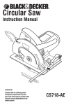
1
Service
Service Manual
Manual
Model
: LCDM-1000
(Cash Dispensing Unit)
Total Page : 41 pages (including cover)
Date
:
Version :
November, 2005
V3.53(INT)
PULOON Technology Inc.
LCDM-1000
Revision Record
Rev. No
Date
Description of Change
Page
V3.0(INT)
02.04.01
V3.51(INT)
04.12.10
Over-Reject Action Added
P.30~33
V3.52(INT)
05.11.23
Rated consuming current
P.4
V3.53(INT)
07.02.05
Add Motor Stop Error Cause
P.29
1
PULOON Technology Inc.
LCDM-1000
= Contents =
1. Functional Description
1-1. Introduction
1-2. Specification
1-3. Cash Cassette Structure
1-4. Feed Module Structure
2. H/W Constitution
2-1. Main Board Parts Layout
2-2. Main Board Connector Layout
3. Error Code & Recommended Actions
3-1. Error Code
3-2. Recommended Actions
4. Operating the LCDM-1000
2
PULOON Technology Inc.
LCDM-1000
1. Functional Description
1-1. Introduction
This Specification is related to LCDM-1000 which is applied to
ATM for Retail Market & other Bill Exchanger.
LCDM-1000 consists of Feed Module,Cash Cassette,Reject Tray
& Main Controller.Features is below
CASH OUT
MAIN CONTROLLER
REJECT TRAY
CASH
CASSETTE
AUTO CASH FEEDER
3
DOUBLE FEEDING
DETECTION
PULOON Technology Inc.
LCDM-1000
1-2. Specification
No
Term
1
Denomination
2
Cassette Capacity
Approx. 1,000 notes (123mm)
3
Dispensing Speed
3 note/sec.
4
Usage Notes Size
height : 62mm~78mm ,
width : 100mm~162mm
5
Double Feeding Detection
6
Reject Tray Capacity
7
Access Type
Front Type
8
Input Voltage
DC 24V
9
Interface
RS 232C
10
Dimension
11
Near-End Detection
12
Bill-End Detection
Specifications
1 denomination
Included (Mechanical Method)
Approximate 30 notes
310.2(D) x 225(H) x 270.5(W)
( Unit:mm)
Approx. 30 ~50 notes
0 or Approx. 10~30 notes
(by setting dip switch,
refer to product spec chapter 4.4)
Load current, continuous
MIN - 0.16A
MAX - 1.4A
Load current, peak
Max - 3.6A
13
Rated Consuming Current
14
Operation Temperature
15
Storage Temperature
-10 °C ~ 60 °C
16
Operation Humidity
20% ~ 80% RH
17
Storage Humidity
10% ~ 90% RH
5 °C ~ 40 °C
4
PULOON Technology Inc.
LCDM-1000
1-3. Cash Cassette Structure
Cash cassette do the role of transporting inserted bill one by
one to next module and consists of Cassette Door,Cassette Body
& Cassette base
Cassette Door
Door Open Direction
Insert Locker
Cash Plate
Cassette Handle
Cash Plate Stopper
Cash Plate Handle
5
PULOON Technology Inc.
LCDM-1000
1-3-1. Capacity & Currency of Cash cassette
Capacity is approximately 123 mm( I.E about 1,000 bills can be
stacked base on new note) & usable currency dimension is as below diagram
Minimum
Maximum
Height
Width
Height
Width
62mm
100mm
78mm
162mm
1-3-2. Cash cassette door
Cash cassette door is magnetically closed & can be opened
If pushed label direction without special locker
1-3-3. Cash Cassette Body
Cash cassette body consists of frame,pushing plate & stopper.
Pushing plate moves bill to “Pick-up roller” along with side- slot by power of spring.
Hook & Axle of stopper is in the rear of “pushing plate & frame” respectively.
Stopper is automatically closed & opened by backing pushing plate and
opening door respectively.
1-3-4. Cash Cassette Base
When cash cassette is inserted, the part of transporting open automatically
by the function of Cash cassette base which is located in the part
of transporting part.
6
PULOON Technology Inc.
LCDM-1000
1-3-5. Bill-End Detection
The Bill-End detection can be decided by dip switch (the 1st switch on the S2).
If you set the switch “ON”, the unit continues to dispense until approximately
10~30 bills remains, and then Bill-End sign will displayed with stopping the unit.
Else if you set the switch “OFF”, the unit continues to dispense until none of bills
remain, and then Bill-End sign will displayed with stopping the unit.
There is hole in the front of “Cash Cassette” and detection process is done
by this hole. ( Please refer to the layout of sensor for location)
7
PULOON Technology Inc.
LCDM-1000
1-4. Feed Module Structure
Feed Module consists of auto cash feeder part , double feeding detection part ,
diverting mechanism part , cash delivery part and Feature is shown below.
Feed motor
Note Path
(Delivery)
Diverter
Pick-up Roller
One-way Roller
Double Detect Roller
8
PULOON Technology Inc.
LCDM-1000
1-4-1. Auto Cash Feeder Part
(1)
Reverse Roller
Feed Roller
Feed Gear
Idle Roller 1
Idle Roller 2
(2)
(6)
(3)
(5)
(4)
< Auto Cash Feeder >
9
PULOON Technology Inc.
LCDM-1000
(1) Features
- Friction roller feeding
- Feeding speed : 3 bills/sec
- Force transportation by clutch on/off
(2) Description
NO
Description
Function
(1)
SHAFT PICK-UP ROLLER ASS’Y
Pick-up & moving bills in the cash
cassette
(2)
SHAFT SPACE CONNECTION ASS’Y
Force transportation of (1) & (4) parts
(3)
ROLLER IDLE
Moving bills by spring force
(4)
SHAFT FEED ROLLER ASS’Y
Separation & moving bills which was
picked up
(5)
BEARING R-1030
Moving bills by spring force
(6)
SHAFT ONEWAY ROLLER ASS’Y
Separation of bills which was pick-up
10
PULOON Technology Inc.
LCDM-1000
1-4-2. Double Feeding Detection Part
(6)
(7)
(1)
(3)
(4)
(2)
(5)
< Constitution of Thickness Recognition >
11
PULOON Technology Inc.
LCDM-1000
(1) Features
- Thickness recognition by Mechanical Amplification
- Thickness recognition by RVDT segment for rotation
(2) Description
NO
Description
Function
(1)
SHAFT FEED ROLLER ASS’Y
DATUM ROLLER of thickness recognition
Outer dimension is important
(2)
BEARING R 1240
DETECT ROLLER, amplification role
with rotation as the center of (4) part
(3)
RVDT segment (LP06M3R)
Recognize rotation displacement
Minute & fast speed of recognition
(4)
ARM D/D HINGE
DETECT ROLLER’ rotation LINK
and transporting rotation power to (7)
(5)
SPRING RVDT TENSION
Push power to DETECT ROLLER
(6)
PLATE D/D SENSOR
RVDT’ rotation STOPPER and transporting
exact displacement using Elasticity
(7)
LEVER D/D HINGE
Transporting (4) rotation power with
amplification using RVDT
12
PULOON Technology Inc.
LCDM-1000
1-4-3. Diverting Mechanism Part
(2)
(5)
(3)
(1)
(4)
(8)
(6)
(7)
< Constitution of divergence part >
13
PULOON Technology Inc.
LCDM-1000
(1) Features
- A sheet resentment by DC Solenoid
- Simplification of Transportation part by Single PATH Method
(2) Description
NO
Description
Function
(1)
SOLENOID 1040 JUWON
SOLENOID for Divergence
(2)
SOLENOID PLUNGER
PULL TYPE method PLUNGER
(3)
LINK SOLENOID STAMP
Transporting SOLENOID’ round trip
movement
(4)
SHAFT DIVERTER ASS’Y
(normal location)
GUIDE of transportation part & move
according to SOLENOID’ movement
Decision of EJECT & REJECT
(5)
SHAFT DIVERTER ASS’Y
(REJECT movement location)
(6)
SHAFT ASS’Y CASH FEED 3
Bill moving ROLLER
(7)
ROLLER ASS’Y IDLE 13
Bill moving ROLLER
(8)
SOL SENSOR
Checking the Diverter solenoid
14
PULOON Technology Inc.
LCDM-1000
1-4-4. Transportation part
(1)
Features
- This part consists of working ROLLER & subordinate ROLLER
- Transportation GUIDE is MOLD GUIDE and embodiment of JAM FREE
- Upper part can be easily separated for Maintenance
(2) Constitution
(h)
(p)
(q)
(g)
(o)
(e)
(k)
(j)
(n)
(i)
(d)
(f)
(a)
(l)
(c)
(b)
(m)
< Constitution of Transportation part >
15
PULOON Technology Inc.
LCDM-1000
- Segment Name
NO
Name
(a)
SHAFT ASS’Y PICK-UP ROLLER
(b)
SHAFT ASS’Y FEED ROLLER
(c)
SHAFT ASS’Y ONEWAY ROLLER
(d)
SHAFT ASS’Y CASH FEED 1
(e)
SHAFT ASS’Y CASH FEED 2
(f)
SHAFT ASS’Y CASH FEED 3
(g)
SHAFT ASS’Y CASH FEED 4
(h)
SHAFT ASS’Y CASH FEED 5
(i)
SHAFT ASS’Y CASH FEED 6
(j)
SHAFT ASS’Y CASH FEED 6
(k)
SHAFT ASS’Y CASH FEED 6
(l)
GUIDE CASH FEED 1
(m)
GUIDE CASH FEED 2 ASS’Y
(n)
GUIDE CASH FEED 3 ASS’Y
(o)
GUIDE CASH FEED 5 ASS’Y
(p)
GUIDE CASH FEED 6 ASS’Y
(q)
GUIDE CASH FEED 7 ASS’Y
16
PULOON Technology Inc.
LCDM-1000
1-4-4. Function & Layout of SENSOR
The number of Sensor is 12. The function & Layout is shown below.
(1) Layout of SENSOR
(12)SOL SENSOR
(3)(4)DIV SENSOR 1 / 2
(6)EXIT SENSOR
(5)EJT SENSOR
(10)WHEEL SENSER
Note Path
(Delivery)
(8)REJECT TRAY S/W
(9)CASSETTE SENSOR
(7)NEAREND SENSOR
(1)(2)CHK SENSOR 1 / 2
17
(9)RVDT SENSOR
PULOON Technology Inc.
LCDM-1000
(2) Function of SENSOR
NO
SENSOR Name
Function
(1)
CHK SENSOR 1
Recognition & Length,Width & Slope checking of
bill from Cash cassette(motor side)
(2)
CHK SENSOR 2
Recognition & Length,Width & Slope checking of
bill from Cash cassette(solenoid side)
(3)
DIV SENSOR 1
Recognition of bill location & role of divergence
movement(motor side)
(4)
DIV SENSOR 2
Recognition of bill location & role of divergence
movement(solenoid side)
(5)
EJT SENSOR
Recognition of normal bill location
(6)
EXIT SENSOR
Recognition of the location & the number of
normal bill
(7)
NEAREND SENSOR
Recognition the number of remaining in the CASH
CASSETTE
(8)
REJECT TRAY S/W
Checking the status of REJECT TRAY
(9)
RVDT SENSOR
Recognition of thickness of transported bill
(10 WHEEL SENSOR
)
(11) CASSETTE SENSOR
Checking the CASH CASSETTE
(12)
Checking the Diverter solenoid
SOL SENSOR
Control of transporting MOTOR speed
18
PULOON Technology Inc.
LCDM-1000
1-4-5. Power Transportation part
[1] Features
• Transportation part work by single MOTOR and power for Bill separation
part is transferred & controlled by CLUTCH
[2] Constitution
G1 T3
P4
G1
G1
G2
P3
G1
G2
P3
MOTOR
G2
P2
P1
P3
T1
T2
P4
CLUTCH
P4
P7
P5
P6
T4
19
PULOON Technology Inc.
LCDM-1000
- Segment Name
NO
Name
Function
G1
GEAR FEED
(Z:27, M:1)
GEAR for transporting ROLLER
G2
GEAR DFDM DRIVE
(Z:27, M:1)
GEAR for transporting POWER
P1
PULLEY MOTOR
(XL16, ¢6)
PULLEY MOTOR
P2
PULLEY CASH FEED 1
PULLEY for reduction of speed
P3
PULLEY CASH FEED 2
PULLEY for transporting ROLLER
P4
PULLEY FEED
(XL15,¢8)
PULLEY for transporting ROLLER
P5
PULLEY FEED
(XL20, ¢8)
PULLEY for FEED ROLLER working
P6
PULLEY DRV MXL17
For reduction speed of ONEWAY ROLLER
P7
PULLEY REVERSE
(MXL42,¢8)
For reduction speed of ONEWAY ROLLER
T1
BELT TIMING 108XL
(W=6.4)
For MOTOR running & Speed reduction
T2
BELT TIMING 140XL
(W=6.4)
For transporting torque to PULLEY
( driving belt )
T3
BELT TIMING 108XL
(W=6.4)
For transporting torque to PULLEY
( driving belt )
T4
BELT TIMING 56MXL
(W=3.2)
For ONEWAY ROLLER running & Speed
Reduction
(3) MOTOR
- MAKER : Fuji Micro
- TYPE : Brushless DC Motor
TYPE
Voltage
FB-806
DC 24V
No Load
Load
Current
Speed
Torque
Current
Speed
180mA±1
00mA
4800rpm
±250rpm
1kgf-cm
2400mA±
200mA
3500rpm
±200rpm
20
Rot
CW/
CCW
PULOON Technology Inc.
LCDM-1000
2. H/W Constitution
2-1. Layout of MAIN BOARD
DIP SWITCH
SENSOR Circuit
CPU,ROM,RAM
RVDT
Circuit
EEPROM
Solenoid,Clutch
BLDC MOTOR
RS232
Communication
Circuit
24V 5V
Conversion
Circuit
21
PULOON Technology Inc.
LCDM-1000
2-2. Connector Layout of MAIN BOARD
J4
J5
J18
J7
J8
J1
JP1
J2
J9
J3
J10
J6
JP3
J4
CHK1,DIV1 Sensor for accepting & emitting sensor
J5
EJT,EXIT emitting sensor
J18
Reject tray switch , Cassette Sensor,SOL sensor
J7
EJT,EXIT accepting Sensor
J8
CHK2,DIV2 accepting & emitting Sensor
J9
Diverter Solenoid
J10
Clutch
JP3
RS232 Communication
J6
Power
J3
Brushless DC Motor
J2
Wheel Sensor
JP1
RVDT
J1
Near-end Sensor
22
PULOON Technology Inc.
LCDM-1000
3. Error Code & Recommended Actions
3-1. Error code
Code
Meaning
Recommended
Action
30H
GOOD
31H
Normal stop
32H
Pickup error
TABLE 1
33H
JAM at CHK Sensor
TABLE 2
34H
Overflow bill
TABLE 3
35H
JAM at EXIT Sensor or EJT Sensor
TABLE 3
36H
JAM at DIV Sensor
TABLE 4
37H
Undefined command
38H
Bill-End
TABLE 10
3BH
Note request error
TABLE 11
3CH
Counting Error(between DIV Sensor and EJT
Sensor)
TABLE 3
3DH
Counting Error(between EJT Sensor and EXIT
Sensor)
TABLE 3
3FH
Reject Tray is not recognized
TABLE 5
41H
Motor stop
TABLE 6
43H
Timeout(From DIV Sensor to EJT Sensor)
TABLE 3
44H
Over Reject
TABLE 7
45H
Cassette is not recognized
TABLE 8
47H
Dispensing timeout
TABLE 1
49H
Diverter solenoid or SOL Sensor error
TABLE 9
4AH
SOL Sensor
TABLE 9
4EH
Purge error(JAM at DIV Sensor)
TABLE 4
23
PULOON Technology Inc.
LCDM-1000
3-2. Recommended Actions
TABLE 1
CODE
32H, 47H
Meaning
Pickup error
Check
Point
- Is CASH CASSETTE located properly?
- Is Bill inserted proper in the CASH CASSETTE ?
- Is Push plate work smoothly in CASH CASSETTE?
- Is any bill out from CASH CASSETTE?
Action
- Re install CASH CASSETTE after checking above
< Normal loading >
< Abnormal loading >
24
PULOON Technology Inc.
LCDM-1000
TABLE 2
CODE
33H
Meaning
JAM at CHK Sensor
Check Point
- Is CHK SENSOR 1& 2 normal?
- Is the assembling condition of GUIDE CASH FEED 1& GUIDE
CASH FEED 3 ASS’Y normal ?
- Is idle roller rotation in the GUIDE CASH FEED 2 ASS’Y
normal?
- Is fixing screw in GUIDE CASH FEED 1 / 2 / 3 ASS’Y normal?
Action
- Try again after checking above situation.
- In case of Jam, Turn a knob shown below
25
PULOON Technology Inc.
LCDM-1000
TABLE 3
CODE
34H, 35H, 3CH, 3DH, 43H
Meaning
- Overflow bill
- JAM at EXIT Sensor or EJT Sensor
- Counting Error(between DIV Sensor and EJT Sensor)
- Counting Error(between EJT Sensor and EXIT Sensor)
- Timeout(From DIV Sensor to EJT Sensor)
Check
Point
- Are EXIT SENSOR & EJT SENSOR normal?
- Is LOCKING device in GUIDE CASH FEED 7 ASS’Y
locked normally?
- Is idle roller rotation status in GUIDE CASH FEED 7 ASS’Y
normal?
Action
- Try again after checking above situation.
- Replace ASS’Y in case of roller rotation problem in GUIDE
CASH FEED 7 ASS’Y.
26
PULOON Technology Inc.
LCDM-1000
TABLE 4
CODE
36H, 4EH
Meaning
- JAM at DIV Sensor
- Purge error(JAM at DIV Sensor)
Check Point
- Is DIV SENSOR 1 / 2 normal?
- Is GAP between SHAFT DIVERTER ASS’Y and SHAFT ASS’Y
CASH FEED proper?
- Is idle roller rotation in GUIDE CASH FEED 5 ASS’Y normal?
Action
- Try again after checking above situation.
- In case of interference between SHAFT DIVERTER ASS’Y &
SHAFT ASS’Y CASH FEED 3, Adjust location of SOLENOID
PIN( Please refer to below picture)
- Replace ASS’Y in case of idle roller rotation problem in GUIDE
CASH FEED 7 ASS’Y.
Solenoid and
Solenoid pin should
be adjusted in
arrow direction
27
PULOON Technology Inc.
LCDM-1000
TABLE 5
CODE
3FH
Meaning
REJECT TRAY is not recognized
Check Point
- Is the location of REJECT TRAY normal?
- Is the location of J18 CONNECTOR normal?
Action
- Insert REJECT TRAY to main body.
- Connect J18 CONNECTOR in the MAIN PCB.
28
PULOON Technology Inc.
LCDM-1000
TABLE 6
CODE
41H
Meaning
Motor stop
Check
Point
- Is any obstacle in Power Transportation part?
- Is the location of J3 CONNECTOR correct?
- Is the location of J2 CONNECTOR correct?
- Is the wheel sensor normal or not?
- Is the wheel assembled on its center point properly?
(Is the wheel assembled with biased position?)
Action
-Try again after checking above situation.
- Check J3 CONNECTOR.
- Check J2 CONNECTOR
- Replace with new wheel senor (Interrupt sensor)
- Assemble the wheel on the center position.
J4
J5
J18
J7
J8
J1
JP1
J2
J9
J3
J10
J6
JP3
29
PULOON Technology Inc.
LCDM-1000
TABLE 7
CODE
44H
Meaning
Over Reject
Check
Point
- Are the banknotes normally loaded in the CASH CASSETTE ?
- Are the DIP SWITCHES properly set to your banknotes?
- Check the reject code referred to the below Table 7-1.
( To catch the reject code on TEST PROGRAM, you should
set the dip switch #3 to OFF like the Table 7-2. )
Action
- Please do the proper service action for each case referred to
the Table 7.
< Table 7-1 : Reject Code>
Reject
Code
Suspected Cause
33
The distance between banknotes is too close.
3F
One more banknote is picked and followed in the final
pickup trial.
36
One more banknote is picked up during the processing the
dispense command.
38
The banknote is skewed too much on the diverter sensor.
3C
The banknotes suspected as double are detected.
3D
The thickness of banknote is abnormally thin.
35
The banknote length is so long that it may be the overlapped
banknotes.
3E
The banknote length is so short that it may be the damaged
or folded banknote.
9C 80
Either check sensor could not detect the banknote.
9C 9E
9C 9F
The length measured on check sensors is not out of limit.
9C 9D
The banknote passed on check sensors is considered as too
much skewed.
9C 03
9C 00
The banknote are not normally passing on the check sensor
because of fast consequential pickup.
30
PULOON Technology Inc.
LCDM-1000
TABLE 7
CODE
44H
Meaning
Over Reject
< Table 7-2 Dip Switch Setting for Display of Reject Code >
ON
OFF
S2 : 1
2
3
4
S1: 1
2
3
4
< Choice of Currency >
ON : Height of Note 73mm ~ 78mm
OFF: Height of Note 62mm ~ 72mm
< Operation Mode >
ON : On-Line Operation
OFF: Auto Test in Lab.
< Baud Rate >
ON : 9600 bps
OFF: 38400 bps
<Thickness Criterion >
ON : 0.10 ~ 0.12 (ex. USD)
OFF: 0.13 ~ 0.15 (ex. CAD)
<Display of Reject code >
ON : Non-Display
OFF: Display
< Definition of Bill-End (option) >
ON : 10~30 remain
OFF: No bill remains
!! Please turn on power again after changing the Dip Switch !!
31
PULOON Technology Inc.
LCDM-1000
TABLE 7
CODE
44H
Meaning
Over Reject
< Table 7-3 Over Reject by Double Detect Problem (Code: 3C) >
Case 1. PLATE D/D SENSOR deflected by external force.
: It should be positioned like the picture and attached to RVDT SENSOR
BLOCK and PIN properly.
: If the deflection is too serious, you should replace with new ones.
Case 2. Abnormal RVDT Sensor, Shaft Error in Production
: It is rare case but sometimes the sensor or shaft error in production
causes such a over-reject. It should be very serious and difficult
to fix that in customer’s house. It is recommended the RVDT should
be replaced with new one.
32
PULOON Technology Inc.
LCDM-1000
TABLE 7
CODE
44H
Meaning
Over Reject
< Table 7-4 Abnormal Clutch or Pick-up Roller (Code: 9C 03, 9C 00) >
It may be caused by the out-of-quality clutch, which is sticking to the power
transmission all the time. So the clutch should be replaced with new one.
Otherwise, the abnormal pick-up roller may cause the over-reject. It needs
replacement with new one, in order to fix the problem.
< Table 7-5 Skew, Obstacle on Path (Code: 9C 80, 9C 9D, 9C 9E, 9F) >
In case of piece cut from the bad banknote or improper material on the path,
it enables to cause the skew amplification, which can occur over-reject.
The note be changed with new one or the path should be cleared by dispensing
the thick note size paper.
33
PULOON Technology Inc.
LCDM-1000
TABLE 8
CODE
45H
Meaning
Cassette is not recognized
Check
Point
- Is Cassette fully inserted to main body?
- Is the location of J18 CONNECTOR correct?
Action
-Try again after checking above situation.
- Check J18 CONNECTOR
34
PULOON Technology Inc.
LCDM-1000
TABLE 9
CODE
49H, 4AH
Meaning
- Diverter solenoid or SOL Sensor error
- SOL Sensor error
Check
Point
- Is the location of J18 CONNECTOR correct?
- Is the location of J9 CONNECTOR correct?
Action
-Try again after checking above situation.
- Check J18 CONNECTOR.
- Check J9 CONNECTOR
J4
J5
J18
J7
J8
J1
JP1
J2
J9
J3
J10
J6
JP3
35
PULOON Technology Inc.
LCDM-1000
TABLE 10
CODE
38H
Meaning
- Bill-End
Check
Point
- Is enough notes in the CASH CASSETTE?
Action
- Loading notes in the CASH CASSETTE
36
PULOON Technology Inc.
LCDM-1000
TABLE 11
CODE
3BH
Meaning
-Note request error
Check
Point
- Is requested dispensing notes of one transaction correct?
Action
- Dispensing notes of one transaction is from 1 note to 20
notes
37
PULOON Technology Inc.
LCDM-1000
4. Operating the LCDM-1000
I. SETUP
1) Start the test program “LCDMTP”
2) Maintain default value like below.
(If you need to choose another port, check the other
port number)
3) Press “OK” button
< Fig 1 : SETUP PAGE >
38
PULOON Technology Inc.
LCDM-1000
II.
MENU
1)
Choose LCDM-1000 or LCDM-2000
< Fig 2 : MENU PAGE >
39
PULOON Technology Inc.
LCDM-1000
2)
DISPENSE
(1) Check UPPER
(2) Fill in the blank of “Upper Request Count” and “Repeat
Count” (Recommended Values are from 1~20 for the XXX
Request Count, and 1~999 for the Repeat Count)
(3) Press the button of “DISPENSE”
<Fig 3 : Ten bills are dispensed 1time from cassette>
40
PULOON Technology Inc.
LCDM-1000
(4) If Near-End occurs, V mark is checked at “Upper Empty”
<Fig 4 : Near-End occurs>
41
PULOON Technology Inc.
LCDM-1000
3)
PURGE
If you want to clear the note in the path, press the button of “Purge”
<Fig 4 : Purge>
42
PULOON Technology Inc.
LCDM-1000
III.
STATUS
1)
Press “STATUS” button and all sensors are rechecked.
This shows system status for you.
2)
If sensor error occurs, V mark is checked at each column
accordingly.
< Fig 5 : STATUS PAGE >
43
PULOON Technology Inc.
LCDM-1000
IV.
1)
TP
This page is about test program for checking each function and element
of the unit.
2)
Motor Speed, Bill Length, Test Dispense, Diverting, RVDT Value, ROM
Version and Clutch Tests can be performed and examined.
3) The recommended values are shown in the Fig. 7 of next page.
< Fig 6 : TP PAGE >
44
PULOON Technology Inc.
LCDM-1000
No.
Command
Element
Check Points
Rec. Range (TP)
1
BLDC
SPEED
Motor
Rotation Speed
6800 ~ 7800
2
RVDT
No Load
-5 ~ +5
(Allowance)
Optical
Sensor
(Length)
USD, CAD, etc
(app. 63~70 mm )
29 ~ 3E
KRW, JPY, etc
( app. 73~80 mm )
2F ~ 47
Normal
Higher than 0500
Double
Lower than 0500
Normal
Higher than 0430
Double
Lower than 0430
Normal
Higher than 04C0
Double
Lower than 04C0
USD
3
BILL LEN
RVDT
Sensor
(Thickness
)
CAD
AUD
NZD
4
CLUTCH
Clutch
Operation Test
On/Off
5
DIVERT
Solenoid
Operation Test
On/Off
45
PULOON Technology Inc.