Transcript
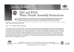
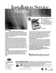
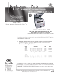
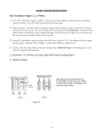
Service Bulletin
ES 5M Series Steamer
Pump Handle Replacement Installation Kit # 1400-20
CAUTION: Read and understand this service bulletin thoroughly before starting. Only
a trained, experienced service technician should attempt this service procedure.
Item #
1
2
3
4
5
Kit # 1400-20 contains the following:
Part #
Description
1400-25
Pump Handle Weldment
1400-30
Pin Punch
Hardware
5/32” x 7/8” long Spring Pin
8699-25
Sleeve Tube (1″)
8471-62
Service Bulletin
Qty
1
1
1
1
1
1
Front Control
Panel Screw
Figure 1
Front Control
Panel Screw
ITEMS NEEDED FOR REPLACEMENT OF HANDLE
Phillips screwdriver
Hammer (brass faced or soft faced hammer recommended)
4
3
CAUTION: BEFORE ATTEMPTING SERVICE, SHUT
OFF ALL POWER TO THE STEAMER AND ALLOW THE
STEAMER TO COOL. PUT ON SAFETY GLASSES.
1.
2.
3.
4.
5.
Pin
Figure 2
Sleeve Tube Assembly
6.
INSTRUCTIONS FOR REPLACEMENT OF HANDLE
Unplug the steamer and remove the two screws from front
control panel. (Fig. 1)
Release the spring tension by removing the spring ends
from the spring seats. (Fig 4)
Remove pin from handle shaft using supplied pin punch.
with a brass or soft faced hammer. (Fig. 3) Discard old pin.
Pull handle out.
Insert the new handle through the crank assembly and
the coils of the spring.
Figure 3
2
With the handle in the correct orientation position (see
Fig 3), align the hole in the handle shaft to the crank
assembly hole.
7. Place plastic sleeve on punch tip approximately 1/2 the
way on the shaft. Insert and seat spring pin into the
plastic sleeve to hold the pin during installation
8. Insert new pin through the handle shaft hole and crank
assembly hole. (Fig 3)
9. Re-set the tension in the spring by compressing the
spring ends and position them in the correct groves on
the spring seats. (Fig 4)
10. Replace the control panel and tighten the two screws. (Fig 1)
11. Re-connect the power supply to the steamer.
Spring Seat
(Back)
Spring Location
(Behind Crank
Assembly)
Spring
Coil
Spring Ends
Spring Seat
(Front)
Shaft of
Handle
Figure 4
Spring and Spring Seats - Top View
AVOID ERROR IN PARTS SELECTION. When ordering use complete EmberGlo Part Number
and Description. Furnish the Product Model Number, Bill of Material Number and Serial Number
(if available) from the specification plate found on the product.
IMPORTANT: Availability of parts as well as specifications are subject to change without notice.
Please consult factory for item availability.
EmberGlo
A Div of Midco® International Inc.
4140 West Victoria Street
Chicago, Illinois 60646
toll free 866.705.0515
tel
773.604.8700
fax
773.604.4070
web
www.emberglo.com
e-mail [email protected]
SAFETY INFORMATION TERMS: The following terms are used to identify hazards, safety precaution of
special notations and have standard meanings throughout this manual. They are printed in all capital letters
using a bold type face as shown below, and preceded by the exclamation mark symbol. When you see the
safety alert symbol and one of the safety information terms as shown below, be aware of the hazard potential.
DANGER:
Identifies the most serious hazards which will result in severe personal injury or
death.
WARNING: Signifies a hazard that could result in personal injury or death.
CAUTION: Identifies unsafe practices which would result in minor personal injury or product and
property damage.
Quality Designed for Proven Performance
711
8471 62
Printed in USA