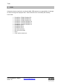
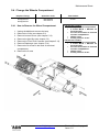
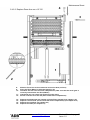
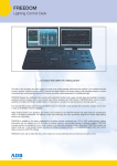
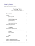
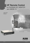
1
WARP Zoom Profile Spotlights Service Manual Issue 1.0 M 5093 1106.55.093 Foreword Foreword This version 1.0 of the Service Manual for WARP precedes the complete manual for the WARP. The latest version of ADB Service Manuals is available from the ADB website. www.adblighting.com For WARP and Motorised WARP www.adblighting.com > ADB Products > Theatre Luminaires > WARP Motorised Zaventem, 8 February 2010. www.adblighting.com Service Manual - page 1 Issue 1.0 Index 1 Index Foreword ................................................................................................................................. 1 1 Index ................................................................................................................................ 2 2 Introduction..................................................................................................................... 3 ABOUT THIS GUIDE ................................................................................................................................ 3 3 Tools ................................................................................................................................ 4 4 Spare Parts...................................................................................................................... 5 4.1 4.2 5 CODE DESCRIPTION ...................................................................................................................... 5 SPARE PARTS FOR THE MANUAL WARP ........................................................................................ 6 Maintenance Sheet ......................................................................................................... 9 5.1 HOW TO CHANGE THE LAMP ASSEMBLY .......................................................................................... 9 5.2 REMOVE / CHANGE THE LIGHT BOX .............................................................................................. 11 5.3 REPLACE THE REFLECTOR .......................................................................................................... 12 5.4 CHANGE THE WHEELS COMPARTMENT ........................................................................................ 13 5.4.1 How to Remove the Wheel Compartment ....................................................................... 13 5.4.2 How replace the Wheel Compartment on a 12°-30° ...................................................... 14 5.4.2.1 Replace Focus Arm on a 12°-30°.............................................................................................. 14 5.4.2.2 Replace Zoom Arm on a 12°-30° .............................................................................................. 15 5.4.3 How replace the Wheel Compartment on a 22°-50° ...................................................... 16 5.4.3.1 Replace Focus Arm on a 22°-50°.............................................................................................. 16 5.4.3.2 Replace Zoom Arm on a 22°-50° .............................................................................................. 17 5.5 REPLACE THE BACK LENS ON 12°-30° WARP ............................................................................. 18 5.6 REPLACE THE FRONT LENS ON 12°-30° WARP ........................................................................... 19 5.7 REPLACE THE BACK LENS ON 22°-50° WARP ............................................................................. 20 5.8 REPLACE THE FRONT LENS ON 22°-50° WARP ........................................................................... 21 5.9 CHANGE GEARS & BELTS ON 12°-30° & 22°-50° ......................................................................... 22 5.10 REPLACE TEFLON RING .......................................................................................................... 23 5.11 REMOVE / CHANGE FRONT FILTER CASSETTE .......................................................................... 24 5.12 REPLACE LENSES COVER ....................................................................................................... 25 5.13 REPLACE DIAPHRAGM ............................................................................................................ 26 5.14 REPLACE WHEEL HANDLE ...................................................................................................... 27 5.14.1 Lens wheel ....................................................................................................................... 27 5.14.2 Shutter wheel ................................................................................................................... 28 5.15 HOW TO ADJUST BRAKE ON LENS WHEEL ................................................................................ 29 Service Manual - page 2 Issue 1.0 www.adblighting.com Introduction 2 Introduction About This Guide This manual is for the service and maintenance of WARP. It is intended to serve as a reference for personnel who are trained in the service and repair of the WARP. WARP is warranted for one (1) year from the date of purchase. ADB assumes no responsibility for damage to units occurring from improper service or being adjusted contrary to these instructions. These units will not be covered by this warranty. The following procedures are designed to be performed by a qualified service technician. This document is intended as a guide and does not provide the detail necessary for a novice to make repairs. “Spare Parts Kit” list contains the parts required to make repairs described in this document. Always disconnect the power to the system before dismantling any component to avoid shorts and possible component damage. www.adblighting.com Service Manual - page 3 Issue 1.0 Tools 3 Tools Adequate tools are required to service the WARP. ADB assumes no responsibility for damage to units occurring from improper tools. These units will not be covered by this warranty. List of tools: • • • • • • • • • • • • • Screwdriver Philips Standard # 0 Screwdriver Philips Standard # 1 Screwdriver Philips Standard # 2 Screwdriver Positive Standard # 0 Screwdriver Positive Standard # 1 Screwdriver Positive Standard # 2 Screwdriver Flat 1 Screwdriver Flat 2 Screwdriver Flat 3 Nut driver set metric Hex. driver set metric Pliers Cutter, pliers wrench set Service Manual - page 4 Issue 1.0 www.adblighting.com Spare Parts 4 Spare Parts 4.1 Code Description The chart below describes how the “Spare part numbers” are build-up. 1001 . 6X . XXX Spare Part Code 60: Conventional WARP 61: Motorised WARP Head 65: Motorised Yoke 1001.60. XXX to 1001.61.XXX: 000-190: Light Box 200-290: Wheel Compartment 300-590: Lenses 800-990: Mechanic 1001.65.XXX: 000-190: Top Box 200-390: Boards 400-590: Wiring 600-790: Motors 800-990: Mechanic Example: 1001.61.000 1001 => spare part 61 => Motorised WARP Head 000 => Light Box www.adblighting.com Service Manual - page 5 Issue 1.0 Spare Parts 4.2 Spare Parts for the Manual WARP Sub Assembly WARP Lamp Assembly Reflector Complete Light Box Code Number 1001.60.000 1001.60.010 1001.60.020 Chapter 5.1 5.4 5.3 Sub Assembly Complete Wheel Compartment 12°-30° Complete Wheel Compartment 22°-50° Brake Lense Wheel Kit Code Number 1001.60.200 1001.60.210 1001.60.220 Chapter 5.5 5.5 5.16 Sub Assembly Back Lens 12°-30° Kit Front Lens 12°-30° Kit Back Lens 22°-50° Kit Front Lens 22°-50° Kit Belt Kit for WARP/M 12°-30° Belt Kit for WARP/M 22°-50 Teflon Ring Kit Diaphragm 12°-30° Diaphragm 22°-50° Code Number 1001.60.300 1001.60.310 1001.60.320 1001.60.330 1001.60.340 1001.60.350 1001.60.360 1001.60.370 1001.60.380 Chapter 5.6 5.7 5.8 5.9 5.10 5.10 5.11 5.14 5.14 Sub Assembly Focus Arm 12°-30° Zoom Arm 12°-30° Focus Arm 22°-50° Zoom Arm 22°-50° Code Number 1001.60.400 1001.60.410 1001.60.420 1001.60.430 Chapter 5.10 5.10 5.10 5.10 Sub Assembly Filter Cassette Lenses Cover 12°-30° Lenses Cover 22°-50° Code Number 1001.60.500 1001.60.510 1001.60.520 Chapter 5.12 5.13 5.13 Sub Assembly Code Number 1001.60.800 1001.60.810 1001.60.820 1001.60.830 Chapter 5.2 5.2 5.15 5.15 Yoke Yoke Handle Lens Wheel Handle Shutter Wheel Handle Service Manual - page 6 Issue 1.0 www.adblighting.com Spare Parts Spare part code for WARP 12°-30° 1001.60.800 (Chapter 5.2) 1001.60.810 (Chapter 5.2) 1001.60.000 (Chapter 5.1) 1001.60.010 (Chapter 5.4) 1001.60.200 (Chapter 5.5) 1001.60.020 (Chapter 5.3) 1001.60.300 (Chapter 5.6) 1001.60.510 (Chapter 5.13) *** 1001.60.340 (Chapter 5.10) **** ** * 1001.60.410 (Chapter 5.10) 1001.60.370 (Chapter 5.14) 1001.60.400 (Chapter 5.10) 1001.60.310 (Chapter 5.7) * 1001.60.360 (Chapter 5.11) ** 1001.60.820 (Chapter 5.15) *** 1001.60.830 (Chapter 5.15) **** 1001.60.220 (Chapter 5.16) www.adblighting.com 1001.60.500 (Chapter 5.12) Service Manual - page 7 Issue 1.0 Spare Parts Spare part code for WARP 22°-50° 1001.60.800 (Chapter 5.15) 1001.60.810 (Chapter 5.15) 1001.60.000 (Chapter 5.1) 1001.60.010 (Chapter 5.4) 1001.60.020 (Chapter 5.3) 1001.60.210 (Chapter 5.5) 1001.60.320 (Chapter 5.8) *** 1001.60.420 (Chapter 5.10) **** ** 1001.60.520 (Chapter 5.13) * 1001.60.430 (Chapter 5.10) 1001.60.350 (Chapter 5.10) 1001.60.380 (Chapter 5.14) 1001.60.330 (Chapter 5.9) * 1001.60.360 (Chapter 5.11) ** 1001.60.820 (Chapter 5.15) *** 1001.60.830 (Chapter 5.15) **** 1001.60.220 (Chapter 5.16) Service Manual - page 8 Issue 1.0 1001.60.500 (Chapter 5.12) www.adblighting.com Maintenance Sheet 5 Maintenance Sheet 5.1 How to change the lamp assembly Required Tool(s) Spare Part Code Time needed Flat Screw Driver Screw Driver PZ1 1001.60.000 15 min. Before Change the lamp Assembly Unplug the WARP and remove the lamp: 1001.60.000 includes: 1 complete lamp assembly 4 M3 * 10 Taptite+ 1 M3*6 2 Finger screws + springs 1 - Open the Lamp Holder 2 - Keep the security cable on the peak and flat cylinder 3 - Remove it from the old lamp assembly (screw which fix the earth wire). 4 - Pass the safety cable through the Lamp Cable hole of the new lamp handle. Spring 65 - Fix the safety cable on the new lamp Assembly, using the Screw M3*6 (put the washer between lamp plate and earth wire). 7- www.adblighting.com Finger Screw Unclose the New Lamp Assembly using the 4 black taptite screws. Screw the 2 Finger Screws with the 2 springs. Service Manual - page 9 Issue 1.0 Maintenance Sheet Required Tool(s) Spare Part Code Time needed Metric Wrench 13 1001.60.800 1001.60.810 5 min. 1. Unplug the WARP 2. Remove the break Handle 3. Remove nuts and washer using Wrench 13, on the two sides. 4. Open the yoke (bend arms) to extract WARP 1001.60.800 includes: 1 Yoke 2 brake Disk All nuts, spacers and washers 1 Handle 1001.60.810 includes: 1 Handle 1 Washer 1 Screw 1001.60.810 Bend the yoke to extract WARP 1 3 2 Service Manual - page 10 Issue 1.0 www.adblighting.com 2 Maintenance Sheet 5.2 Remove / Change the light Box Required Tool(s) Spare Part Code Time needed Hexagonal H4 1001.60.020 5 min. 1. Unplug the WARP and remove the lamp: 2. Remove the 2 screws into the wheels compartment using H4 3. Remove / Replace the Light Box and the 4 Plastic spacers WARNING: Don’t forget the 4 plastic spacers when you replace the light Box m: 1001.60.020 includes: 1 complete light box 2 Screws M5 * 40 + 2nuts 4 plastic Spacers Plastic Spacer 2 1 2 1 www.adblighting.com Service Manual - page 11 Issue 1.0 Maintenance Sheet 5.3 Replace the Reflector Required Tool(s) Spare Part Code Time needed Hexagonal H4 Pozidrive PZ2 1001.60.010 20 min. 1. Unplug the WARP and remove the lamp: 2. Remove the Light Box from the WARP (see Chapter 5.3) 3. 4. 5. 6. 7. Remove the 2 Cones for heat Remove screws M3 on the Front of the cone (PZ2) Remove Screws H4 on the back (near the Peak and Flat) Open the Light box Replace the Reflector 1001.60.010 includes: 1 reflector 4 reflector Springs 2 Screws M 3 * 12 + 2 washers 2 Nuts M3 auto block 3 4 WARNING: First Time you change the reflector, you have to replace taptite screws (front of the sink) by screws M3*12 (provided with spare parts 1001.60.010) Cone for Heat Reflector Spring 5 1 2 Service Manual - page 12 Issue 1.0 www.adblighting.com Maintenance Sheet 5.4 Change the Wheels Compartment Required Tool(s) Spare Part Code Time Needed Screw Driver PZ2 Hexagonal H4 Hexagonal H5 1001.60.200 1001.60.210 30 min. 5.4.1 How to Remove the Wheel Compartment 1. Unplug the WARP and remove the lamp 2. 3. 4. 5. 6. 7. Remove the Yoke (see chapter 5.2) Remove Lenses Covers (see chapter 5.13) Remove the light Box (see chapter 5.3) Remove the Front Filter Cassette (see chapter 5.12) Remove Diaphragm (see chapter 5.14) Remove the 4 screws in the back of the wheel compartment 8. Remove the 2 arms 1001.60.200 includes: 1 complete Wheel Compartment 2 screws M6*30 + Washers for Front Cassette 4 screws and washer to fix Arms on wheel compartment 3 Black rivets 2 safety cable for 12-30° 1001.60.210 includes: 1 complete Wheel Compartment 2 screws M6*30 + Washers for Front Cassette 4 screws and washer to fix Arms on wheel compartment 3 Black rivets 2 safety cable for 22-50° 4 2 6 1 5 www.adblighting.com 3 Service Manual - page 13 Issue 1.0 Maintenance Sheet 5.4.2 How replace the Wheel Compartment on a 12°-30° 5.4.2.1 Replace Focus Arm on a 12°-30° 4 3 2 1 123- 4567- Service Manual - page 14 Issue 1.0 Slide the Back Lens to the mechanical End on the Arm (on front) Place the focal Wheel as indicated (position G + 1 increment) Introduce the Arm into the wheel compartment (Take care that the small gear is correctly connected to the focal Wheel) Check that you can control the focal using the wheel Put the 2 screws to fix the arm (back of the wheel compartment) Slide the Focal until 0 position Introduce the diaphragm (see chapter 5.14) www.adblighting.com Maintenance Sheet 4 5.4.2.2 Replace Zoom Arm on a 12°-30° 3 1 2 8910 11 12 - Slide the Front lens to the mechanical end on the Arm (on front) Place the Zoom Wheel as indicated (position 12) Introduce the Arm into the wheel compartment (Take care that the small gear is correctly connected to the Zoom Wheel) Check that you can control the Zoom using the wheel Put the 2 screws to fix the arm (back of the wheel compartment) 13 14 15 16 - Replace the diaphragm (see chapter 5.14) the Filter Cassette (see chapter 5.12) Replace Lenses Cover (screw inside the wheel compartment) (see chapter 5.13) Replace the Light Box (see chapter 5.3) Replace the Yoke (see chapter 5.2) www.adblighting.com Service Manual - page 15 Issue 1.0 Maintenance Sheet 5.4.3 How replace the Wheel Compartment on a 22°-50° 5.4.3.1 Replace Focus Arm on a 22°-50° 5 4 3 2 1 12345678- Slide and Remove the Back Lens from the arm. Put the Belt Clip near the front gear. Place the focal Wheel as indicated (position D) Introduce the Arm into the wheel compartment (Take care that the small gear is correctly connected to the focal Wheel) Introduce the lens support into the arm profile and screw it on the belt clip Check that you can control the focal using the wheel (0-Full) Put the 2 screws to fix the arm (back of the wheel compartment) Slide the Focal until 0 position Introduce the diaphragm (see chapter 5.14) Service Manual - page 16 Issue 1.0 www.adblighting.com Maintenance Sheet 5.4.3.2 Replace Zoom Arm on a 22°-50° 4 3 2 910 11 - 1 12 13 - Slide the Front lens to the mechanical end on the Arm (on front) Place the Zoom Wheel as indicated (position 7) Introduce the Arm into the wheel compartment (Take care that the small gear is correctly connected to the Zoom Wheel) Check that you can control the front lens using the wheel Put the 2 screws into the arm 14 15 16 17 - Replace the diaphragm (see chapter 5.14) the Filter Cassette (see chapter 5.12) Replace Lenses Cover (screw inside the wheel compartment) (see chapter 5.13) Replace the Light Box (see chapter 5.3) Replace the Yoke (see chapter 5.2) www.adblighting.com Service Manual - page 17 Issue 1.0 Maintenance Sheet 5.5 Replace the Back Lens on 12°-30° WARP Required Tool(s) Spare Part Code Time Needed Screw Driver PZ2 1001.60.300 10 min. 1. Unplug the WARP 2. 3. 4. 5. 6. 7. Open the two lenses cover Remove the Diaphragm (see chapter 5.14) Put Front and back lenses at Full Remove the 3 taptite screws from the Lens plate Remove the 3 Isolations and the ADB Clip. Change the Lens Service Manual - page 18 Issue 1.0 www.adblighting.com 1001.60.300 includes: Back Lens 12-30° 3 New screws 3 Isolations 3 ADB Clip. Maintenance Sheet 5.6 Replace the Front Lens on 12°-30° WARP 1. 2. 3. 4. 5. 6. 7. Required Tool(s) Spare Part Code Time Needed Flat Screw Driver Screw Driver PZ2 1001.60.310 10 min. Unplug the WARP Open the two lenses cover and remove the diaphragm (see chapter 5.14) Put Front and back lenses at 0 Remove the 9 Taptite Screws and the front lens plate 1001.60.310 includes: Remove the 2 screws and the 2 spacers Front Lens 12-30° Remove the 4 isolations and Clips 10 New screws for Lens plate Change the Lens 4 Isolations www.adblighting.com 4 ADB Clip. 2 Screws Service Manual - page 19 Issue 1.0 Maintenance Sheet 5.7 Replace the Back Lens on 22°-50° WARP Required Tool(s) Spare Part Code Time Needed Screw Driver PZ2 1001.60.320 10 min. 1. Unplug the WARP 2. 3. 4. 5. 6. 7. Open the two lenses cover Remove the Diaphragm (see chapter 5.14) Put Front and back lenses at Full Remove the 3 taptite screws Remove the 3 Isolations and the ADB Clip. Change the Lens Service Manual - page 20 Issue 1.0 www.adblighting.com 1001.60.320 includes: Back Lens 22-50° 3 New screws 3 Isolations 3 ADB Clip. Maintenance Sheet 5.8 Replace the Front Lens on 22°-50° WARP Required Tool(s) Spare Part Code Time needed Screw Driver PZ2 1001.60.330 10 min. 1. Unplug the WARP 2. 3. 4. 5. 6. Open the two lenses cover Put Front and back lenses at 0 Remove the 3 screws Remove the 3 isolations and Clips Change the Lens www.adblighting.com 1001.60.330 includes: Front Lens 22-50° 3 New screws 3 Isolations 3 ADB Clip. Service Manual - page 21 Issue 1.0 Maintenance Sheet 5.9 Change Gears & Belts on 12°-30° & 22°-50° Required Tool(s) Spare Part Code Time Needed Screw Driver PZ2 Metric Wrench 10 1001.60.340 1001.60.350 1001.60.400 1001.60.410 1001.60.420 1001.60.430 45 min. Important: On the WARP you have to remove Arms to change all gear and belt. To replace Arms correctly, please see chapter 5.5.2 for 12°-30° and chapter 5.5.3 for 22°-50°. 1. Unplug the WARP 2. Remove arms from WARP (see chapter 5.5.1) 3. Use wrench 10 to remove gear shafts 1001.60.410 1001.60.340 & 1001.60.350 include: 2 Belts T3 * 420 2 Belt Clip Screw washer and nut for Belt Clip 4 Lens Gears and Washer 2 gear Shaft 8 Washers M8 1001.60.400 1001.60.340 1001.60.430 1001.60.350 Service Manual - page 22 Issue 1.0 www.adblighting.com 1001.60.420 Maintenance Sheet 5.10 Replace Teflon Ring Required Tool(s) Spare Part Code Time None 1001.60.360 30 min. Important: After a few years of operation, it could be necessary to change the Teflon ring to facilitate the sliding of the lenses. 1. Unplug the WARP 2. 3. 4. 5. 6. 7. 8. Open Covers and remove Filter Cassette (see chapter 5.12) Remove Diaphragm (see chapter 5.14) Unlink the 2 lenses from belts (remove screws and nuts from the belt clip) Slide and remove completely lenses support from arms Change all Teflon parts as initially assembled on each lens support Replace lenses into arm profile. 1001.60.360 includes: 10 Lens Stears Replace Diaphragm Filter Cassette and covers 5 Lens Opened Stears 3 Lens Gliders 1001.60.360 Glider www.adblighting.com Service Manual - page 23 Issue 1.0 Maintenance Sheet 5.11 Remove / Change Front Filter cassette 1. 2. 3. 4. Required Tool(s) Spare Part Code Time needed Screw Driver PZ2 Hexagonal H5 1001.60.500 10 min. Unplug the WARP Open the two lenses cover Remove the 2 screws M6 on the front Remove the Filter Cassette 1001.60.500 includes: 1 Complete Filter Cassette 2 screws M6 * 30 2 Locking Washers 2 Safety Wire Attachment WARNING: Due to mechanical adjustment, some WARP were manufactured with a small sheet spacer between the filter cassette and arms. Before you remove the cassette, make note of the spacer position, to replace it correctly. Don’t forget the Safety Wire Attachment Service Manual - page 24 Issue 1.0 www.adblighting.com Maintenance Sheet 5.12 Replace Lenses Cover 1. 2. 3. 4. 5. Required Tool(s) Spare Part Code Time Needed Screw Driver PZ2 1001.60.510 (12°-30°) 1001.60.520 (22°-50°) 10 min. Unplug the WARP Open the two lenses cover Put the Back Lens at 0 and the Front Lens at Full Drill the 2 rivet on covers Remove covers and replace new one www.adblighting.com 1001.60.510 includes: 2 complete 12°-30° Covers 4 black rivets 1001.60.520 includes: 2 complete 22°-50° Covers 4 black rivets Service Manual - page 25 Issue 1.0 Maintenance Sheet 5.13 Replace Diaphragm Required Tool(s) Spare Part Code Time Needed None 1001.60.370 1001.60.380 2 min 1. Unplug the WARP 2. Open the two lens covers 3. Press on diaphragm arms and remove it from wheel compartment. Diaphragm 12°-30° 1001.60.370 Press here 1001.60.370 includes: 1 Diaphragm 12°-30° 1001.60.380 includes: 1 Diaphragm 22°-50° Press here Diaphragm 22°-50° 1001.60.380 Service Manual - page 26 Issue 1.0 www.adblighting.com Maintenance Sheet 5.14 Replace Wheel Handle 5.14.1 Lens wheel Required Tool(s) Spare Part Code Time Needed Screw Driver PZ1 1001.60.820 10 min 1. Unplug the WARP 2. Remove the 2 screws into handles 1001.60.820 includes: 4 Big blue handle zoom-focus 8 screws M3*12 www.adblighting.com Service Manual - page 27 Issue 1.0 Maintenance Sheet 5.14.2 Shutter wheel Required Tool(s) Spare Part Code Time Needed Flat Screw Driver 1001.60.830 5 min 1. Unplug the WARP 2. Insert the flat screwdriver between the wheels and remove the blade handle 3. Replace the blade handle 1001.60.830 includes: 9 Blade handle Insert the flat screwdriver here Service Manual - page 28 Issue 1.0 www.adblighting.com Maintenance Sheet 5.15 How to adjust Brake on Lens Wheel Required Tool(s) Spare Part Code Time Needed Flat Screw Driver Metric Wrench 7 1001.60.220 5 min 1. Put the WARP Downwards 2. Release lock nut A (use 8 Metric Wrench) 3. Adjust the friction with screw B (use screw driver) Don’t block the ball inside the screw Good adjustment: the wheel could manually turn the lens can’t fall when WARP Downwards 4. Tighten the lock nut A Notice: 1001.60.220 includes: 2 Pression Screws 2 Nuts If the ball is out of the screw, you must change the complete screw B A B www.adblighting.com Service Manual - page 29 Issue 1.0 Maintenance Sheet Notes Service Manual - page 30 Issue 1.0 www.adblighting.com France ADB S.A.S. Sales Office: 92, Avenue Jean Jaurès F-92120 Montrouge Tel : +33.1.41.17.48.50, Fax : +33.1.42.53.54.76, E-Mail : [email protected] Factory & Group Logistics Centre: Zone industrielle Rouvroy F-02100 Saint-Quentin Tel : +33.3.23.06.35.70, Fax : +33.3.23.67.66.56, E-Mail : [email protected] www.adblighting.com Subject to modifications N.V. ADB-TTV Technologies S.A. (Group Headquarters) Leuvensesteenweg 585, B-1930 Zaventem Tel : +32.2.709.32.11, Fax : +32.2.709.32.80, E-Mail : [email protected] M-5093-E-03r ADB - Your Partner for Light Belgium