1
tighting and Signaling
Circuit Operation
and Diagnosis
OBtrXCf IVES: After studying Chapter
18,
the reader
should be able to:
l.
Prepare for ASE Electrical/Electronic Systems (46)
certification test content area "E" (Lighting System
#*HE; This flickering on and off is misunderstood by
many drivers and technicians. Because the flickering is
rapid, many people believe that the problem is caused
by a loose headlight or by a defective voltage regulator.
Diagnosis and Repair)
2.
Determine which replacement bulb to use on
a
given vehicle.
3. Describe how turn signals work.
4" Use a bulb chart.
5. Discuss troubleshooting procedures for
This feature allows the headlights to function, as a
safety measure, in spite of current overload. The
headlight switch controls the following lights on
most vehicles:
lighting and
1. Headlights
2. Taillights
3. Side marker lights
4. Front parking lights
D. Dash lights
6. Interior (dome) Iight(s)
signaling circuits.
Ell
E he lighting and signaling circuits represent two of
the most frequently serviced automotive electrical
areas.
ffi LIGHTIT*G
Exterior lighting
is
controlled by the headlight
switch, which is connected directly to the battery on
most vehicles. Therefore, if lights are lefb on, it can
drain the battery. Most headlight switches contain a
built-in circuit breaker. If excessive current flows
through the headlight circuit, the circuit breaker
will momentarily open the circuit, then close it
again. The result is headlights that flicker on and off
rapidly.
$\6ffiTffi1 Because these lights can easily drain the battery if accidentally left on, many newer vehicles control
these lights through the vehicle's computer. The computer keeps track of the time the lights are on and can
turn them offif the time is excessive. The computer can
control either the power side or the ground side ofthe
circuit.
ffi
EUtB NI.'MBERS
The number used on automotive bulbs is called the
bulb trade numbe4 as recorded with the American
National Standards Institute (ANSI), and the number
is the same regardless of the manufacturer. Ambercolor bulbs that use natural amber glass are indicated
4tl
412
CHAPTER
18
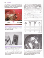
with an "NA' for naturq,l amber at the end of the number (for example, #1157NA). A less expensive amber
bulb that uses painted glass is labeled'.lt''for amber
(for example, #1157A). See Figure 18-1.
*ffi*
3t s?
/;
*t*rfx/
Typical Automotive Lighl Bulbs
3t57NA
/*t:t:{ffA,
l8-l
Bulbs that have the same trade number have
the same operating voltage and wattage. The NA means
that the bulb uses a natural amber glass ampoule for use
with clear turn signal lenses.
Figure
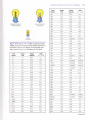
The trade number also identifies the size, shape,
number of filaments. and amount of light produced.
The amount of light produced is measured in candlepower. For example. the candlepower of a #1156
bulb, commonly used for backup lights, is 32. A #194
bulb, commoniy used fol dash or side marker lights,
is rated at only 2 candlepori-er. The amount of light
produced by a bulb is deternined b1- the resistance
of the filament wire, rn'hich also afiects the amount of
current (in amperes) required b., ihe bulb. See Figures 18-2 and 18-3.
It is important that the correct tlade number of
bulb always be used for replacement to crei-ent circuit or component damage. The con"ect rep:acenent
bulb for your vehicle is usually iisted in :1. o\\-ner's
manual or service manual. See Fizur'e 1E--1 and the
bulb chart.
Trade
Number
37
37E
3l
53
55
57
57X
Design Design Watts:
Volts AmPeres P:lxE
.3
0.09
14.0
.3
0.09
14.0
1.7
0.22
7.5
1.7
0)2
14.4
2.9
0.41
7.0
3.4
0.24
140
3.4
0.24
14.0
1
1
(continued)
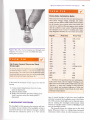
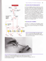
Figure lS-2 This single-filament bulb is being tested with
to read resistance in ohms. The
reading of | .3 ohms is the resistance of the bulb when
a digital multimeter set
cold. As soon as current flows through the filament,the
resistance increases about l0 times. lt is the initial surge of
current flowing through the filament when the bulb is cool
that causes many bulbs to fail in cold weather as a result of
the reduced resistance. As the temperature increases, the
resistance increases.
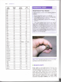
Figure l8-3 Close-up of a dual-filament (double filament)
bulb (# | 157) that failed. Notice that one filament (top)
brol<e from its mounting and melted onto the lower
filament. This bulb caused the dash lights to come on
whenever the bral<es were applied.
Lighting and Signaling Circuit Operation and Diagnosis
413
Trade Design Design Watts:
Number Volts Amperes P-lxE
12.8
0.97
12.4
562
13.5
0.74
10 0
563
tJ.c
0.52
70
0.63
8B
30
1
906
14.0
12.8
12.8
13.0
912
0Jl
DOUBLE CONTACT
1
.157/2057
WEDGE
194 BULB
Figure l8-4 Bulbs #l157 or #2057 are typically used for
taillight and front parking lights. These bulbs contain both a
low-intensity filament for taillights or parl<ing lights and a
high-intensity filament for brake lights and turn signals.
67
IJ,J
0.59
8.0
68
tJ.c
0.59
8.0
70
14.0
0.15
2.1
73
14.0
0.08
1.1
AA
14.0
0.10
1.4
81
6.5
1.02
6.6
88
13.0
0.58
7.5
89
13.0
0.58
7.5
90
13.0
0.58
7.5
93
12.8
1.04
IJ.J
94
12.8
1.04
t.t.J
14.0
168
0.24
3.4
'14.0
0.19
2.7
14.0
0.35
4.9
192
13.0
0.33
AE
194
14.0
0.27
3.8
194E-1
194NA
14.0
14.0
0.27
0.27
209
211-2
212-2
4-2
21
6.5
12.8
13.5
3.5
1
1.78
0.97
0,74
.52
0
12.8
1003
1004
1034
1073
076
1129
1133
12.8
12.8
12.8
12.8
12.8
6.4
6.2
0.94
0 94
1.80/0 59
1.80
.80
2.63
3.91
1141
12.8
t.44
18.4
1.44
18.4
2.63t0.75
16.8t4.5
2]0
26.9
1
1142
1154
1156
1157
1157A
1157NA
1176
1195
1196
1445
1816
1BB9
11.6
4.4
161
1.00
2721
0.63
27.0
12.8
3.8
7.0
27.0
90
3.8
63
2.10
2.10
0.69
12.8
6.4
12.8
12.8
12.8
12.8
12.8
12.5
12.5
14.4
I3.0
14.0
891
14.0
892
4.4
1893
14.0
14.0
1895
'13.5
2033
2057
12.8
2057NA 12.8
2322-1 12.0
Trade Design Design Watls:
Number Volts Amperes P:lxE
ICd
880
881
SINGLE CONTACT
1 1 56 BULBS
BULBS
1
1
1
1
2.10/0.59
2.10/0.59
2.10t0.59
1.34/0.59
3.00
3.00
0.13
0.33
0.27
0.24
12.0
12.A
23 0t7 .6
23
0
23.0
16.8
24.2
26.9t7.6
26.9t7 .6
26.9t7.6
17.2t7.6
37 .5
37.5
1.9
4.3
3.8
3.4
0.12
0.33
0.27
4.6
0.22
3.0
1
.7
3.8
2.1010.48
26.9t6.1
2.10t0.48
26.9t6.1
0.16
2.0
12.0
0.10
1.2
2821
12.0
4.00
3.0
12.4
2825
12.0
0.42
5.0
10.0
3057
12.8
0.16
z.l
3157
12.0
1.10
7
.0
12.8
(continued)
4t4
CHAPTER I8
Trade
Number
3796
3893
Design Design Walts:
AmPeres P:lxE
Volts
2.0
6.00
12.0
4.0
3.00
12.0
IYeird Problem-Easy Solution
A General Motors minivan had the following electrical
3894
12.0
4.00
3.0
problems:
3898
12.0
6.00
2.0
3966
12.0
4.00
J.U
r
r
The turn signals flash rapidly on the left side.
With the ignition key of, the lights-on warning chime
5004
12.0
4.00
3.0
1.20
5.0
sounds if the brake pedal is depressed.
When the brake pedal is depressed,the dome light
5006
6.0
o
5.0
5007
12.0
2.40
5008
12.0
1.20
10.0
6418
12.0
0.42
5.0
0.25
3.0
comes on.
All of these problems were caused by iust one defective 2057 dual-filament bulb shown in Figure l8*5.
Apparently,the two filaments were elecrically connected
through the corrosion observed between the terminals
of the bulb. This caused the electrical current to feed
back from the brake light filament into the taillight circuit
causing all the problems. See Figure l&-6 for another example of a weird bulb problem.
6461
7230
12.0
12.0
12.0
/JU
I
12.0
3.75
45,0
7309
12.0
2.92
35,0
7506
12.0
0.60
21.0
7527
0.69
18.0
7533
9004 H.
9005 H*
9006 H^
12.0
12.0
12.0
12.8
12.8
12.8
26736
6428
7528
0.83
2.40
2.40
10.0
5.0
5.0
0.80
15.0
5.00/35.00
65.0/45.0
5.00
65.0
4.30
55.0
12.0
0.83
10.0
12.0
4"50
55.0
12.0
12.0
12.0
12.0
12.0
4.50
8.30
8.30
4.50
8.30
12.0
2.90
12.0
13.5
13.5
5.00
.86
R19/5
13.5
0.37
R19/10
w10/3
13.5
13.5
0.74
0.25
H1
64151 H3
64152 H1
64153 H3
64173 H2
64174 H2
64.185 H4
64193 H4
P25-1
P25-2
64150
1
1
.86
55.0
100.0
100.0
55.0
100.0
35.0
60.0
25j
Figure l8*5 Corrosion caused the two terminals of this
dual-filament bulb to be electrically connected.
25.1
c.
l
10.0
3.4
ffi BTTAKE LI€HTS
Brake lights use the high-intensity frlament of a
double-filament bulb. (The lower intensitl- filament
is for the taillights.) The brake light sri'itch is a normally open (N.O.) switch but is closed rvhen the
driver depresses the brake pedal. Since 1986, all vehicles sold in the United States have a third brake
light commonly referred to as the center high'
mounted stop light (CHMSL). The brake switch
Lighting and Signaling Circuit Operation and
Heavy-Duty Automotive
Diagnosis 4l5
Butbs
Many automotive bulbs have the same operating param-
eters (same wattage, voltage, amperage, and candlepower) yet have different trade numbers. Some numbers
are for standard duty, whereas others have heavier filament wire or additional filament support, which qualifies
them for a different trade number. A fleet-duty designation represents some increase in durability, and a heavyduty designation identifies the most severe service bulb.
#
Regular
-i.
d.'F
-#
Figure l8-6 Cften rhe besr diagnosis is a thorough visual
inspection. This bulb was found to be filled with water,
! No Cruise Controll Check the Third
i Brake Light
182
57
293
67
97
97
68
96
96
69
98
631
90
99
|
1445
|
r58
193
t84
|
003
t05
|
004
104
t98
t94
|
034
|
034A
A common cause of an inoperarive cruise control,especially
|
073
199
on General Motors
il41
I t59
t889/t891
|
chird brake bulb as a ground and shurs offthe cruise if the
bulbs are burned our (openJ, See Figure l8-7.
4000
4040
60t4
60 t5
vehicles. rs a burned out bulb in the
third stop lighr. The cruise conlrol uses rhe filaments of the
is also used as an input srvitch rslsnal) for the following:
1. Cruise control (deactivates when the brake
pedal is depressed)
2. Antilock brakes (ABS)
3. Brake shift interlock (prevents shifting from
"park" position unless the brake pedal is
depressed)
+,
F{EA&L!G*{T
SWETCT-t gS
The headlight switch operates the exterior and interior lights of most vehicles. The headlight switch is
connected directly to the battery through a fusible
link and has continuous power or is "hot" all the
or 53X
895
093
t6l
i
Heavy Duty
53
93
causing weird problems.
Fleet Duty
| 157
il 57NA/ il 57A
893
I t56
|
893
Therefore, if the specification for your vehicle gives a
trade number listed under the "regular" heading, you can
safely switch to the trade number of bulb listed under the
"fleet-duty" or "heavy duty" heading. For best operation
of turn signals and consistent brightness of bulbs, the
switch of trade numbers should include all similar bulbs
of the type being replaced.
time. A circuit breaker is built into most headlight
switches to protect the headlight circuit. See Figure
18-8. The interior dash lights can be dimmed manually by rotating the headlight switch knob, which
controls a variable resistor (called a rheostat) built
into the headlight switch.
The rheostat drops the voltage sent to the dash
lights. Whenever there is a voltage drop (increased
resistance), there is heat. A coiled resistance wire is
I
416
'
CHAPTER
':.:
1 Dx
rliii=:=::?irri:r::-iii
AACI( UP
uclfrs
1 OK BLU
18
BLU
rr:e'::i'
!
::.
75
l
t-1-
l{l r
BRAKE
SwlTCH
CLOSEOWITH
ARAKE PEIAL
DEPRESSED
"
TU&N
,--? FLASTGR
l--.a'
;75
C2G5
{HOr USED}
L=
.8 LT
BLU/i _^^
* 6.v
BLK
I
wHT
m.;:
17
,8
t'
;:- l-'.a. t'-'
t -. t{g.ntll - -t- . -,.. - . 2 - - -l *tt? -. f,
l----;-';:'- {---;'.-- I.
.
O-'ra +
LT
..
x -elu
;"r:.
:
:l
-
.J".-"-/
-=j. ,=e'
i----{
*'o
3
a--'
3
'r.?
A
v<r
' 'it*-'
r
:A
.
.8
-.
wr[
..:
19
*".u!,,
czor
ts
_ _
.r:&r caor
1 -D-{
I
DK GRr{
'DKGRN
,-*
ilgi-'liT^''.
".*
?#fti,'
-
..'T ';;u
3EA GROUNO
DISTRI3UNON
15o
LlGlfT
8==
C318
.8BLXe r50
B€
BLK
ca24
g
150
.ffi..
"ir'
s3l7
c
..0*".u
RH,
6-g
;ffif;.='"'
i,,1,?",,'=,i.1,?,i,..!*5]*ff",.=,,=",{.,?==!!=..,.===:!,.-?!!il,**"*=i3=.t1=.=
s/108
cal8
o
^!/
I
.,cfl
i;'---"-i
.qBN- c325
lill
ca24
820
HIGH L€VEL
STOP
cml
17
820
A€
P
c204
fiII
A$i
Lr BLU
i
'ttr*re
]r*t
"a-a
-,"
I srop-;-mrr" €.3 {dsrf;* €s,,-_.i,i
-.
SWTTCH
.
bL,
.t
-
?l+ Q--t I
-'-"\-i
'--'
\'t
DKGRil
H -'"-..----i
'uot t-t, o* orn
14
:.
BLK
TUR}V
HAZARD
HAZARD SWITCH
Lr
E
BLU/ {fi
t*
s/to4
$,u
g
*--**\r9/
,V.
B,.frHEffi,
,'
''
=::
a2oo
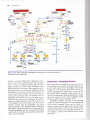
Figure tB-7 Typical brake light and taillight circuit showing the brake switch and all of
the related circuit components.
built into a ceramic holder that is designed to insulate the rest of the switch from the heat and allorv
heat to escape. Continual driving with the dash
lights dimmed can result in the headlight switch
knob getting hot to the touch. This is normal, and the
best prevention is to increase the brightness of the
dash lights to reduce the amount of heat generated
in the switch. The headlight switch also contains a
built-in circuit breaker that will rapidly turn the
headlights on and off in the event of a short circuit'
This prevents a total loss ofheadlights. Ifthe headlights are rapidly flashing on and off, check the entire headlight circuit for possible shorts. The circuit
breaker controls only the headlights. The other
lights controlled by the headlight switch (taillights,
dash lights, and parking lights) are fused separately.
Flashing headlights may also be caused by a failure
in the built-in circuit breaker, requiring replacement
of the switch assembly.
Removing a Headlight Switch
Most dash-mounted headlight switches can be removed by first removing the dash panel. However, to
get the dash panel off, the headlight switch knob
usually has to be removed. Some knobs can be removed by depressing a small clip in a notch in the
knob itself. Other headlight switch knobs are removed by depressing a spring-loaded release, which
allows for removal of the entire headlight switch
knob and shaft as shown in Figure 18-9.
Headlight switches mounted on the steering
column are removed as part of the turn signal and
wiper switch assembly. Many can be easily removed, whereas others require the removal of the
steering wheel and so forth. See the service information for the exact year and model on which you
are working in order to be assured of the correct
procedure.
Lighting and Signaling Circuit Operation and
E.1E
BREAKE
R
c270
--l
HEAD
OFF
]
swrTcH
RIY
c303
DIMMEB
STEERING
COLUMN-
swrTcH
MOUNTED
--
swrTcH
SIALED-BEAM HEADLIGHTS
standardized so that sealed-beam units that can be
purchased at most auto parts stores can replace
them. Because low-beam headlights also contain a
high-beam filament, the entire headlight assembly
must be replaced if either filament is defective.
A sealed-beam headlight can be tested with an
ohmmeter. A good bulb should indicate low ohms between the ground terminal and both power-side (hot)
terminals. If either the high-beam or the low-beam
filament is burned out, the ohmmeter will indicate
infinity (OL). See Figure 18-10.
HEADLIGHT
PARK
MULTIFUNCTION
417
Low-beam headlights contain two filaments: one for
low beam and the other for high beam. High-beam
headlights contain only one filament. Headlights are
BK/O
crRcurT
Diagnosis
LO
F*:
I{EADLIGHT AIMING
According to U.S. federal law, all headlights, regardIess of shape, must be able to be aimed using headlight aiming equipment. See Figures 18-11 through
18-13.
HIGH.BEAM
INOICATOR
LIGHT
s-132
13
R/BK
12
LEFT
RIGHT
DUAL
HIGH
BEAM
BEAM
Figure l8-8 Typical headlight circuit diagram. Note
BK
BK
BK
=
G40l
that the headlight switch is represented by a dotted
outline indicating that other circuits (such as dash lights)
also operate from the switch.
i:'rl'nElEAS:El
Figure l8*9 To remove the headlight switch from a vehicle that uses a knob and shaft,
a release button has to be pushed to release the shaft. After the knob and shaft
assembly has been removed, then the retaining nut can be removed from the headlight switch so it
can be removed from the dash.
4I8
CHAPTEF. IB
TOP ADJUSTING SCREW
2 Lamp system and
circulaf 4 lamp system
S1
DE ADJUSTING SCREW
Lor{
Common
High
Rectangular
4 lamp system
AIMING UNIT
Common
Low
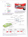
Figure :S-l
I
All vehicles sold in the United States must
have provision for the use of mechanical aiming devices.
Even the halogen bulb units with plastic or glass lenses
High
have locating points and adjustment screws.
Figure N8-10 Typical headlight socket connectlons' Some
vehicles may be different. The high- and low-beam
connections must be determined by visual inspection.
12 FEET
DISTANCE BETWEEN
HEADLAMPS
ADJUSTABLE
VERTICAL TAPES
CENTER LINE OF
SCRTTN
HORIZONTAL CENTER LINE OF LAMPS
------+
ADJUSTABLE
HORIZONTAL
TAPES
VEHICLE AXIS
'-
-'--t"
25 FEET
(7.6 m)
DIAGRAM OF LIGHT SCREEN
PAINTED REFERENCF LINE
ON SHOP FLOOR
VTHICLE
AXIS
VERTICAT
CENTERLINE
AHEAD OF LEFT
HEADLAMP
r
.1-
7
HIGH INTENSITY
AREA
Figure
!8-t?
-
A
VEFTICAL
CENTERLINE
AHEAD OF RIGHT
HFADLAMP
.lz
p
VEHICLE
AXIS
VERTICAL
CENTERLINE
AHEAD OF LEFT
HTADLAMP
HEIGHT OF
LAMP CENTERS
-G
/
\
HIGH
INTTNSITY ABEA
//
HIGH INTENSITY
AREA
Typical headlight-aiming diagram as found in a service manual
p
r
/.
"
/
vEFTICAL
CENTERLINE
AH€AD OF RIGHT
HFADLAMP
HEIGHT OT
LnLap crNrrRs
-4wn rc.
w
\
HIGH
INTTNS1TY AREA
4t9
Lighting and Signaling Circuit Operation and Diagnosis
Diagnose Bulb Failure
Halogen bulbs can fail for various reasons. Some causes for
halogen bulb failure and their indications are as follows:
€
Gray
color-low
voltage
to bulb (check for
corroded socket or connector)
* White (cloudy) color-indication of an air leak
e Broken filament-usually caused by excessive
*
vibration (see Figure l8-15)
Blistered glass-indication that someone
has
touched the glass
Figure
l8-l3
bubble level
Many composite headlights have a built-in
easy and accurate.
to make aiming
i==!*-T"Hi Neyer touch the g/oss ompoule of ony hologen bulb.
The oils from your fingers can cause unequal heating of the
glass during operation, leading to a shorter-than-normal
service life.
Figure l8-14 A typical composite headlamp assembly.
The lens, housing, and bulb sockets are usually included as
a complete assembly.
ffi COMPOSITE HEADLIG*{TS
Composite headlights are constructed using a replaceable bulb and a fixed lens cover that is part ofthe
vehicle. See Figure 18-14. The replaceable bulbs are
usually bright halogen bulbs. Halogen bulbs get very
hot during operation (between 500" and 1300" F [260'
and 700" Cl). It is important never to touch the glass
of any halogen bulb with bare frngers because the
natural oils ofthe skin on the glass bulb can cause the
bulb to break when it heats during normal operation.
'€ HALGGEN SEALED.BEAM
FIEADLIG}ITS
Halogen sealed-beam headlights are brighter and
more expensive than normal headlights. Because of
their extra brightness, it is common practice to have
Figure l8-15 Notice the broken filament in this
headlight bulb.
halogen
420
CHAPTER IB
The temperature of daylight compared to various
types of bulbs includes:
E Daylight-s40O'K
I HID-4100'K
r Halogen-3200'K
I Incandescent (tungsten)-2800'
K
ffi DAYTIME RUNNING LIGHTS
Figure l8-16 HID (Xenon) headlights emit a whiter light
than halogen headlights and usually look blue.
only two headlights on at any one time because the
candlepower output would exceed the maximum
U.S. federai standards if ail four halogen headlights
were on. Therefore, before trying to repair the problem that only two of the four lamps are on, check
with the owner's manual or the shop manual for
proper operation.
CAUTION! Do not attempt to wire all headlights together. The extra current flow could overheat the
wiring from the headlight switch through the dimmer
switch and to the headliehts. The overloaded circuit
could cause a fire.
:.i: E{ I G
H-l ?IITENS|TY
DISE HARGH }IEADTIGFITS
High-intensity discharge (HID) headlights produce a distinctive blue-white light that is crisper,
clearer, and brighter than light produced by a halo-
HID bulb
has no filament. It creates light from an electrical
discharge between two electrodes in a gas-filled arc
tube. It produces twice the light with less electrical
input than conventional halogen bulbs.
The HID lighting system consists of the discharge arc source, igniter, ballast, and headlight assembly. The two electrodes are contained in a tiny
quartz capsule filled with xenon gas, mercury, and
metal halide salts. The lights and support electronics
are expensive, but they should last the life of the vehicle unless physically damaged. See Figure 18-16.
gen headlight. Unlike a halogen bulb, the
Daytime running lights ,DRLs r involve operating
front parking lights or the headlights (usually at reduced cur'r'ent and voltage ) rvhenever the vehicle is
rrrnnino
arrredq hqs renrrirod dor-r.,,,,.r
im, Tunnrng
lights on all nen vehicles since 1990. DRLs have reduced accidents where used.
Dar-time running lights primarily use a control
module that turns on either the low- or high-beam
lamps. The lights on some vehicles come on lvhenever the engine starts. Some vehicles will turn on the
lamps rvhen the engine is running, but delay their
operation until a signal from the vehicle speed sensor indicates that the vehicle is moving.
To avoid having the lights on during servicing,
some sy'stems will turn off the headlights whenever
the palking brake is applied. Others will only light
the headlights when the vehicle is in a drive gear.
see l lsure 16-1 /.
CAUTION: Most factory daytime running lights
op-
erate the headlights at reduced intensity'. These are nol
designed to be used at night. Normal intensitl' of the
headlights (and operation of the other external lamps)
is actuated by turning on the headlights as usual.
-:l=:
DTMMER SIYITCHES
The headlight switch controls the power or hot side
of the headlight circuit. The current is then sent to
the dimmer switch, which allows current to flow to
either the high-beam or the low-beam filament of the
headlight bulb as shown in Figure 16-1E. An indicator light lights on the dash q'hener-er the bright
lights are selected.
The dimmer switch can be eithel foot operated
on the floor or hand operated on the steering column.
The popular steering column su-itches are actually
attached to the outside of the steeling column on
most vehicles and are spring ioaded. To replace most
of these types of dimmer switches. the steering column needs to be lowered slightly to gain access to the
switch itself, which is also adjustable for proper lever
operation.
tI
I
I
l-
I
I
lq---
I
cLosEDrN
NcHTMoDE
I
I
I
HEADLTGHTS
o*.roa..
1
\
II
coNrACr
,'
\(t'
\
-. r- DAr
(lI
-------{
coNrAcr r +
cLosEo I
iN Ncir-i
rrcDE II
FFoflr rAtL I
Lrcrrs oN |
tl
j':"--.{--r
-.u
ET
..*! I'o
*ii rn.
EEI
EI
I
;
.
E
g
;E
i n
E
IUBIU
$f_.,
li;#
I
I
HAZARD
HEADLIGHT
SWITCH
...:
HEAD
I
ASSEi',1BLY
HEAOLIGHT
DIMMFF
i
swrTcH
I'
I
I
r
:
1 TAN
**,
.:.'
16
tt'
"i. t
I
Ef
E
B
E
;;iLL
l!1:
:+pu._^
rArL
LrGHrs
3
1
TAN
5
&
,:^"
12
s1 27
l-'L'o"l''g@sb-
r-;'A---'L
Ld----T\J,::=:=Y_-_-.r::-::":I
,;;;;t;
HHI
fr&o-l
iiffil
-T-x- --J
LO
roxeruunrlsss
iU Jtia
L:-:E-:EE-J
1
"*
2
HEADTIGHT
ASSEMELY
'u'
!
F
I
RH
COMPOSITE
,.^
t
'u'
"1Q
clrs
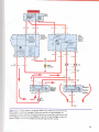
Figure | 8- | 7 Typical daytime running light (DRL) circuit. Follow the arrows from the
DRL module through both headlights. Norice that the left and right headlights are
connected in series, resulting in increased resistance, less current flow, and dimmer than
normal lighting. When the normal headlights are turned on, both headlights receive full
battery volcage, with the left headlight grounding through the DRL modure.
421
422
CHAPTTR I8
Lights
switch
*--*-*rr3-Lead
headlights
Ground
Positive switching
Negative switching
Figa..:re I 8- | I Most vehicles use positive switching of the high- and low-beam
headlights. Notice that both filaments share the same ground connection. Some vehicles
use negative switching and place the dimmer switch between the filaments and the
grouno.
',+
TUffi S{ (Dl
RE€"lOft{At}
SIGNALS
A turn signal flasher unit is a metal or plastic can
containing a switch that opens and closes the turn
signal circuit. See Figure 18-19. This turn signal
flasher unit is usually installed in a metal clip attached to the dash panel to allow the "clicking" noise
ofthe flasher to be heard by the driver. The turn signal flasher is designed to transmit the current to
light the front and rear bulbs on only one side at a
time. The U.S. Department of Transportation (DOT)
regulation requires that the driver be alerted when
a turn signal bulb is not working. This is achieved by
using a series-type flasher unit. The flasher unit requires current flow through two bulbs (one in the
front and one in the rear) in order to flash. Ifone bulb
burns out, the current flow through only one bulb is
not sufficient to make the unit flash; it will be a
steady light. These turn signal units are often called
DOT flashers. When the turn signal flasher unit is
old, the lights will flash more slowly (both sides affected equally). The contact points inside the flasher
Figure I S- i I Two styles of two-prong flashers.
unit may become corroded and pitted, requiring
higher voltage to operate. To restore normal operation, replace the turn signal flasher unit. Other common turn signal problems and possible solutions include the following:
Lighting and Signaling Circuit Operation and Diagnosis
Possible Causes and/
or Solutions
Problem
1. Slow flashing on
both sides equally
1. Replace the worn
flasher unit. Check the
battery and the
charging voltage to be
certain that the
charging circuit and
battery are supplying
high-enough voltage for
proper operation ofthe
frrrn qimqlq
2. Slow or no flashing
on one side only
3.
*
Turn signals not
a flashing on
either side
2. Replace the defective
bulb, or clean poor
connections on the front
or rear bulbs on the side
that does not work.
3. The most likely cause is
defective flasher unit, in
which case replacement
will be necessary.
I{AZARD
Why Does the Side Marker Light
Alternately Flasht
A question that service technicians are asked frequently
is
why the side marker light alternately goes out when the
turn signal is on and is on when the turn signal is off.
Some vehicle owners think that there is a fault with their
vehicle while actually it is normal operation. The side
marker light goes out whenever the lights are on and the
turn signal is flashing because there are | 2 volts on both
sides of the bulb (see points X and Y in Figure l8-20).
Normally, the side marker light gets its ground through
the turn signal bulb.
flashing of the hazard flasher and damage to the
flasher itself.
However, defective bulbs
or connections on both
sides could also be the
= COURTESY LIGI{TS
cause.
Courtesy lights
Most turn signal flasher units are mounted in a
metal clip that is attached to the dash. The dash
panel acts as a sounding board, increasing the
sound of the flasher unit. Most four-way hazard
flasher units are plugged into the fuse panel. Some
two-way turn signal flasher units are also plugged
into the fuse panel. How do you know for sure where
the flasher unit is located? With both the turn signal and the ignition on, listen and/or feel for the
clicking of the flasher unit. Some service manuals
also give general locations for the placement of
flasher units.
€+
423
is a generic term primarily used for
interior lights, including overhead (dome) and underthe-dash (courtesy) lights. These interior lights can
be operated by rotating the headlight switch knob
fully counterclockwise (left) or by operating switches
located in the door jambs of the vehicle doors and.ior
near the dome light. There are two types of circuits
commonly used for these interior lights. Most manufacturers, except Ford, use the door switches to
ground the courtesy light circuit. See Figure 18-27.
Many Ford vehicles use the door switches to open and
close the power side of the circuit.
Many newer vehicles operate the interior
Iights through the vehicle computer or through an
electronic module. Because the exact wiring and
operation of these units differ, consult the service
Iiterature for the exact model on which vou are
working,
FLASHERS
L=::
Hazard flasher units are usually plugged into the fuse
panel and are designed to flash four or more bulbs
safely and at the same flashing speed regardless of
the number of bulbs used in the lighting circuit.
Therefore, if trailer lights are connected to the
taillights, the flasher unit for the four-way hazard
flasher should be used in place ofthe standard turn
signal flasher. However, the regular (DOT) turn
signal flasher cannot be used for the four-way hazard flashers. The result would be the verv ranid
ILLUMINATED ENTRV
Some vehicles are equipped with illuminated entry,
whereby the interior lights are turned on for a given
amount of time whenever the outside door handle is
operated while the doors are locked. Most vehicles
equipped with illuminated entry also light the exterior door keyhole. Some vehicles equipped with body
computers use the door handle electrical switch of
the illuminated entry circuit to "wake up" the power
supply for the body computer.
424
CHAPTER I8
Headlight
swrlch
I
Lelt
turn
1.5 Q
Side
marker
lrght
20!) =
Park
ljght
Figure l8-20 The side marker light goes out whenever there
is voltage at both point
X and Y. These opposing voltages stop current flow through the side marker light. The
left turn light and left parl< light are actually the same bulb (usually a#20s7)
u."
"nd
shown separately to help explain how the side marker light works on many vehicles.
corrected. From the schematic or wiring diagram, the
technician could see where voltage should be at various
parts of the circuit. Not any more! Many of today's vehi_
ctes use a computer to control almost everything, including interior lights. The old switches in the door jamb sim_
ply signal the computer that a door has been opened. The
computer controls the lighting to help control against accidental battery drain. For example, in the event that the
vehicle door has been left open, the computer can open
the circuit and prevent a dead battery.
The schematic rarely shows exactly how the circuit
Figure l8-?
works. However, most service manuals walk you
through the diagnosis. With a service manual, or serv-
|
A typical courtesy light door jamb switch.
Newer vehicles use the door switch as an input to the
vehicle computer and the computer turns on or offthe
interior lights. By placing the lights under the control of the
computer, the vehicle engineers have the opportuniry ro
delay the lights after the door is closed and to shut them
off after a period of time to avoid draining the battery.
i
ice disk if on compact disk with read-only memory (CDROM), the technician is not lost. Always follow the pro-
i
*_
!
f cedures exactly! Even if the service procedure sounds j
I long and involved, the procedure will lead you to the
, correct diagnosis.
!
;
,,..:
Lighting and Signaling Circuit Operation and
ffi FIBER OPTICS
Fiber optics is the transmission of light through special plastic (polymethyl methacrylate) that keeps the
light rays parallel even if the plastic is tied in a knot.
These strands of plastic are commonly used in auto-
motive applications as indicators for the driver that
certain lights are functioning. For example, some \-ehicles are equipped with fender-mounted units that
light whenever the lights or turn signais are operating. Plastic fiber-optic strands, which often look like
standard electrical wire, transmit the light at the
bulb to the indicator on top ofthe fender so rhat the
driver can determine if a certain light is operating.
Fiber-optic strands can also be r.un like rl-ires to indicate the operation of all lights on :he ia-.h or console. Fiber-optic strands are also co:tr::,i:lr- used to
light ashtrays, outside door lc'ck-.. ani ,:,iler areas
where a small amount of ligh: is recrireC. The source
of the light can be anv nor:naih- operating light buib.
A special bulb clip is usualll-used to retain the fiberoptic plastic tube near the bulb.
€ FEEDBACK
When current that lacks a good ground goes backward along the power side of the circuit in search of
a return path (ground) to the battery, this reverse
flow is called feedback or reverse-bias current
flow Feedback can cause other lights or gauges to
work that should not be workins.
\r
Diagnosis
425
Feedback Example
A customer complained that when the headlights
were on, the left turn signal indicator light on the
dash remained on. The cause was found to be a poor
gtound connection for the left front parking light
socket. The front parking light bulb is a dual filament: one filament for the parking tight (dim) and
one frlament for the turn signal operation (bright). A
corroded socket did not provide a good enough
ground to conduct all current required to light the
dim filament of the bulb.
The two filaments of the bulb share the same
glound connection and are electrically connected.
When all the current could not flow through the
bulb's ground in the socket, it caused a feedback or
reversed its flow through the other filament, looking
for ground. The turn signal fiIament is electrically
connected to the dash indicator light; therefore, the
rer-ersed current on its path toward ground could
iight the turn signal indicator light. Cleaning or replacing the socket usually solves the problem if the
ground rvire for the socket is making a secure chassis ground connection.
426
CHAPTER I8
LIGHTING SYSTEM TROUBLESHOOTING GUIDE
.
Burned-out headlight filament. Check the headlight witn an
0hmmeter. There should be a low-ohm reading between the
power-side connection and the ground terminal of the bulb.
Both high- and low-beam headlights out
Burned-out bulbs. Check for voltage at the wiring connecror t0
the headlights (possible open circuit to the headlights or open
Idefective] dimmer switch).
All headlights inoperative
Slow turn signal operation
Turn signals operating on one side only
I
Poor gr0und dim connection on bodv
0ne headlight out (dim or bright)
nterior light(s) inoperative
.
Burned-out filaments in all headlights. Check for proper
charging system voltage
Defective dimmer switch
Defective headlight switch
.
.
. Defective flasher unit
. High resistance in sockets or ground wire connections
. Incorrect bulb numbers
. Burned-out bulb on affected side
. Poor ground connection or defectjve socket on affected side
. Incorrect bulb number on affected side.
. Burned-out bulb(s)
. 0pen in the power-side circuit (blown use)
. 0pen in door jamb switch(es)
. Shorted door jamb switch
. Headlight switch turned fully counterclockwise
. Defective brake switch
. Defective turn signal switch
. Burned-out brake light bulbs
. 0pen circuit 0r p00r ground connection
f
Interior lights on all the time
Brake lights inoperative
Hazard warning lights inoperative
\r
Hazard warning lights blinking too rapidly
Defective hazard flasher uniL
0pen in hazard circuit
.
Incorrect flasher unit
.
Shorted wiring to front or rear lights
lncorrect bulb numbers.
.
l8-l
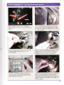
The driver noticed that the taillight fault
indicator (icon) on the dash was on any time the lights
P
were on.
8-2 A visual inspection at the rear of the vehicle
indicated that the right rear taillight bulb did not light.
Removing a few screws from the plastic cover revealed
P|
the taillight assembly.
\r
Pl8-3
The bulb socket is removed from the tailliSht
assembly by gently twisting the base of the bulb
counterclockwise.
P | 8-4 The bulb is removed from the socket by gently
grasping the bulb and pulling the bulb straight out of
the socket. Many bulbs require that you rotate the
bulb 90' (l/4 turn) to release the retaining nibs.
Pf S-5 The new 7443 replacernent bulb is being
checked with an ohmmeter to be sure that it is OK
before installing it in the vehicle.
8-6 The replacement bulb is inserted into the taillight socket and the lights are turned on to verify
proper operation before putting the components back
together. The dash warning light was also off after the
P|
bulb was replaced.
427
CHAPTER I8
ffi SUMMARY
4. Electrical feedback
running or the vehicle is moving.
4. High-intensity discharge (HID) headlights are brighter
and have a blue tint.
5. One defective turn signal bulb causes the turn signal
on the affected side to stop blinking (flashing).
K REVIETY QUESTIONS
1. Explain why the exact same trade number of
bulb should be used as a replacement.
2. Explain why you should not touch a halosen bulb
with your fingers.
3. Describe how to diagnose a turn signal operating
problem.
5. Which bulb is brightest (see the bulb table)?
a. #I94
b. #168
c. #194NA
d.. #57
6. If a #1157 bulb were to be installed in a left front
parking brake socket instead of a #2052 bulb,
what would be the most likely result?
a. The left turn signal would flash faster.
b. The left turn signal would flash slower.
c. The left parking light would be slightly
d.
QUESTTONS
\r
dimmer.
b.
nician is correct?
a. TechnicianAonly
b. Technician B only
c. Both Technicians A and B
d. Neither Technician A nor B
3. Interior overhead lights (dome lights) are operated by door jamb switches that ______*_.
a. Complete the power side of the circuit
b. Complete the ground side of the circuit
c. Move the bulb(s) into contact with the power
and ground
d. Either a or b, depending on application
candlepower is higher.
The amber color of the bulb is a different
shade.
c.
d.
8.
The bulb is dimmer because the #11524.
candlepower is lower.
Both b and c.
A customer complained that every time
he
turned on his vehicle's tights, the left-side turn
signal indicator light on the dash remained on.
The most likely cause is ________.
a. A poor ground to the parking light (or
1. Technician A says that the bulb trade number is
the same for all butbs of the same size. Technician B says that a dual-filament bulb has different candlepower ratings for each filament. Which
technician is correct?
a. Technician A only
b. Technician B only
c. Both Technicians A and B
d. Neither Technician A nor B
2. Two technicians are discussing flasher units.
Technician A says that a DOT-approved flasher
unit should be used only for turn signals. Techni_
cian B says that a variable-load flasher will function for turn signal usage, although it will not
warn the driver if a bulb burns out. Which tech-
brighter.
The left parking light would be slightly
7. A technician replaced a #1157NA with a #11bZA
bulb. Which is the most likely result?
a. The bulb is brighter because the #11574
4. Discuss how to aim headlights on a vehicle
equipped with aerodynamic-style headlights.
ffi ASE CERTIFICATION-TYPE
of
a. Too high a voltage in a circuit
b. Too much current (in amperes) in a circuit
c. Lack ofa proper ground
d. Both a and b
1. Automotive bulbs are identified by trade numbers.
2. The trade number is the same regardless of manufacturer for the exact same bulb specification.
3. Daytime running lights (DRLs) lie'ht the headlights,
usually at reduced intensity, whenever the engine is
is usually a result
taillight) bulb on the left side
b. A poor
ground to the parking light (or
taillight) bulb on the right side causing
current to flow to the left-side lights
(open) parking light (or taillight)
bulb on the left side
A defective (open) parking light (or tailiight)
bulb on the right side
c. A defective
d.
9.
A
defective taillight or front park light bulb
could cause:
a. The turn signal indicator on the dash to light
b.
c.
when the lights are turned on
The dash lights to come on when the brake
lights are on
The lights-on warning chime to sound if the
brake pedal is depressed
All of the above
d.
10. A defective brake switch could prevent proper
operation of the _____
a. Cruise control
b. ABS brakes
c. Shift interlock
d. All of the above