1
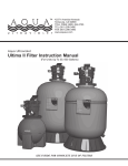
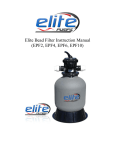
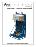
Quick Start Guide
Written and complied by Clayton West with contributions from Scott Armish, Jamie Wagner, Mark Honsowetz and
EFI Technology Inc. Edelbrock LLC. 2011
1
INTRODUCTION:
Thank you for selecting the Edelbrock Pro-Flo EFI System. Engine control in spark ignited engines means
regulating fuel and air intake as well as spark timing to achieve desired performance and economy. Until recently,
fully programmable engine management systems were not available to the typical enthusiast and the ones that
were available, based primarily on OEM systems, were complex and cost prohibitive. Edelbrock's Pro Flo systems
are designed for competition and ultra high performance street vehicles. The systems provide the experienced
installer/tuner with a starting point for any custom application. Pro Flo 2 & XT systems are compatible with high
impedance injectors only or low impedance injectors when used in conjunction with a standalone peak and hold
injector driver box (not included).
CAUTION:
Installation of this product requires detailed knowledge of automotive systems and repair
procedures. We recommend that this installation be carried out by a qualified automotive
technician. Installation of this product requires knowledge of computer systems. It is
recommended that you or someone close to you be fluent in operating a computer or PC.
WARNING:
The fuel system is under pressure. Do not open the fuel system until the pressure has been
relieved. Refer to the appropriate vehicle service manual for the procedure and precautions for
relieving the fuel system pressure. Installation of this product requires handling of gasoline.
Ensure you are working in a well ventilated area with an approved fire extinguisher nearby.
Extinguish all open flames, prohibit smoking and eliminate all sources of ignition in the area of
the vehicle before proceeding with the installation. When installing this product, wear eye
goggles and other safety apparel as needed to protect you from debris and sprayed gasoline.
If you have any questions, do not hesitate to call our
EFI Technical Hotline at (800) 416-8628, 7am-5pm PST, Monday-Friday
Edelbrock EFI system customers can now join others at
http://Forums.Edelbrock.com/Forums/
The forum offers support from current experienced users as well as Edelbrock Tech Reps.
2
NOTICE:
PLEASE REFER TO THE
COMPLETE MANUAL
LOCATED
ON THE INSTALLATION
CD FOR A MORE IN
DEPTH EXPLANATION OF
TUNING,
INSTALLATION AND
FUNCTIONS OF THE
EDELBROCK PRO FLO
EFI SYSTEMS.
UTION
3
Introduction
In this document we will be covering the basic initial set up, start up and high points of interest of the
Pro Flo EFI systems. Please refer to the installation instructions for properly installing your system.
Getting Started
The following section will describe in general. The initial setup and installation of all Pro Flo
EFI systems. Before beginning, please ensure the following:
1. The vehicle's engine is in good mechanical condition. The camshaft and valve train are
properly installed. The engine has good compression and no vacuum leaks or exhaust leaks, etc.
2. The vehicle's electrical system is sufficient for EFI. Edelbrock recommends a good quality lead-acid
cell battery and working alternator for proper voltage.
Installing the Distributor & Setting the Timing
This is an area that can often cause confusion but it is straightforward with a little help. The Pro Flo 2 &
XT systems use Hall Effect style distributors to trigger the ignition and fuel injectors. The ECU needs to
know where the engine is in its cycle so it can properly fire the injectors and spark in sequential mode.
Inside the distributor are a shutter wheel and a sensor, the shutter wheel passes through this sensor
and the sensor sends this information to the ECU which interprets it as engine position. The engine and
ECU need to have a fixed set point to index each other, that set point is 10* BDTC. That means
mechanically the engine is at 10* advanced and any required advance or retard will be added by the
ECU. Once the distributor is in the engine and timed at 10* BTDC, no more adjustment to the distributor
is needed. Use the tips below to install and time your distributor correctly.
The distributors in the Pro Flo EFI systems consist of a shutter wheel that has eight teeth. One of these
teeth is narrower than the other seven; this represents the #1 cylinder of the engine. The shutter wheels
are based on engine rotation, clockwise or counter-clockwise rotation. It is important to make sure your
distributor has the correct shutter wheel for your engine.
Clockwise Rotation
Small & Big Block Chevrolet, Small Chrysler & AMC
Counter-Clockwise Rotation
Small & Big Block Ford, Pontiac & Big Chrysler
4
4
Leading Edge
Leading Edge
As you can see the shutter wheels have a larger gap after the small tooth in relationship to rotation. To
check if you have the correct shutter wheel, compare the shutter wheel in the distributor to the
diagrams. For ProFlo 2, small & big Chevrolet kits the wheel is included in the distributor conversion kit.
For ProFlo XT & other kits that use the Mallory, MSD or Edelbrock distributors you will have to partially
take apart the distributor to accurately verify you have the correct shutter wheel.
1. Start by removing the distributor cap & rotor.
2. Locate the two retaining nuts on the side of the distributor body
3. Turn the nuts counter-clockwise until the retaining tabs inside the distributor rotate upright
4. Push the wire harness into the distributor body and use a 90* pick tool to carefully remove the
circuit board.
Retaining Tab
Shutter Wheel
Retaining Nut
5. The shutter wheel is located beneath the circuit board. Notice on the Mallory distributor that the
shutter wheel is inverted, opposite of the diagrams on the previous page, keep this in mind
when comparing shutter wheels.
6. Compare the shutter wheel with the images to ensure you have the proper shutter wheel.
On some of the other distributors such as the MSD and Edelbrock distributors the process is a little
different. Disassembly is usually not needed except for removing the rotor.
On the circuit board is the Hall Effect sensor that the shutter wheel passes through. The shutter wheel
needs to be located in the Hall Effect sensor correctly so the ECU can properly reference engine
position. The short tooth on the shutter wheel represents the #1 cylinder; this short tooth needs to be
centered in the Hall Effect sensor with the engine at 10* BDTC.
5
Mallory Style Distributor
MSD & Edelbrock Style Distributor
Hall Effect Sensor
Hall Effect Sensor
Above are pictures of the Hall Effect sensors used with Edelbrock ProFlo EFI kits. You can see the slot
in the sensor that the shutter wheel runs through. Once you have determined you have the correct
shutter wheel for your engine, you need to install the distributor.
1. Remove the #1 cylinder spark plug; put your finger over the spark plug hole.
2. Rotate the engine over until the piston comes up the bore and pushes you finger off the hole.
3. While rotating the engine, watch the harmonic balancer & stop when the mark on the balancer
lines up with the 10* mark on the timing pointer.
Now we are ready to install the distributor. When installing the distributor we want to make sure the
leading edge of the small tooth on the shutter wheel is centered in the Hall Effect sensor. With the
Edelbrock & MSD distributors this is fairly easy to do, simply watch the shutter wheel while installing the
distributor and line up the edge of the small tooth in the sensor. If the shutter wheel doesn’t line up
correctly, it is because the oil pump shaft needs to be rotated. Remove the distributor from the engine,
using a long screwdriver; turn the pump shaft the appropriate amount. You may have to repeat this to
get the shutter wheel to line up. You can also rotate the distributor body to get the relationship correct.
If you cannot get it perfect, don’t fret, you can adjust for it later, after fire up.
Center the leading edge of the
narrow tooth in the Hall Effect
sensor of the distributor.
6
Leading Edge
On Mallory distributors, the circuit board needs to be out of the distributor body to properly see the
shutter wheel while installing the distributor. When installing the Mallory distributor, locate the dowel pin
pressed into the distributor body used to locate the cap. Line up the leading edge of the narrow tooth
with this dowel pin. Rotate the oil pump shaft and /or distributor body to line up the tooth properly.
Dowel Pin
Mallory Distributors
Line up the leading edge of the
narrow tooth with the dowel pin in
the distributor body when installing
the distributor.
Narrow Tooth
Once the distributor is installed and the tooth aligned correctly, re-install the circuit board; rotate the
retaining nuts clock wise to secure the retaining tabs. Then re-install the rotor.
All Distributors:
Once the distributor is in the engine
and the rotor is installed, use a
permanent marker to draw a line on
the outside of the distributor body
where the brass tip of the rotor points.
#1 Cylinder Post
Rotor Mark
Install the distributor cap, the line you
drew on the body of the distributor
should line up with a spark plug
terminal or post on the cap. This
terminal is your #1 cylinder spark plug
terminal.
If the rotor does not line up relatively close with a terminal on the cap, make sure engine is not
7
timed 180* out and you have the correct shutter wheel for your engine.
7
Make sure you have the correct spark plugs for your cylinder heads; aftermarket cylinder
require different plugs than stock heads. Improper spark plugs will cause extensive drivability
problems and make tuning very difficult. If you have questions regarding the proper spark plug
for your application, contact your cylinder head manufacturer or call the Edelbrock tech line at
1-800-416-8628.
You can now run your spark plug wires to the proper cylinders in the correct firing order for
your engine.
Timing Tips
When you first start the engine you might notice more ignition advance than you’re used to.
Don’t be alarmed, this is completely normal. This is because with a computer controlled engine
the ECU can alter the timing based on engine load, RPM and throttle opening. With the engine
operating at low load conditions the ECU can advance the timing to improve idle quality and
fuel economy.
It is common to see idle timing as high as 30*or more in high duration, high performance
camshaft equipped engines and 40-50* of timing while cruising, this is equivalent to a vacuum
advance on a distributor. Below is a good guideline for ignition timing at idle:
Stock to mild engines with 15” of vacuum or more: 12-18*
Moderate performance engines with 11” -15” of vacuum: 18-26*
Aggressive engines with radical cams with 11” of vacuum or less: 24-36*
Keep in mind these are just guidelines and not definite for all engines.
Installing & Using the Software
The software package included with the Pro Flo kit is required to load the initial calibration file into your
ECU. An optional software package called bEditor is also included on the supplied CD-ROM. To install
the software, load the supplied CD into your PC’s CD drive. The installation routine should auto run.
Follow the onscreen prompts to install the software and USB to Serial Adapter. eFlash is a standalone
system that can be used to load calibration files or different firmware versions onto an ECU using any
Windows compatible PC. A laptop is not required. The system includes a DC power source that can be
plugged into any standard wall socket. It will provide power to the ECU and allow two way
communications without having to install the ECU in the vehicle. Tuning can then be done using the
handheld module. In addition to allowing flash programming, eFlash has several additional features that
can be useful:
• It displays all ECU data real time in one consolidated view.
8
• It displays all calibration module trims and modifications in
one view so you can see them at a glance.
• It allows you to send your existing calibration file to Edelbrock
tech support personnel using the iLink feature (internet
connection required).
• It allows the user to perform software updates if necessary.
The System Editor is an advanced, yet intuitive development tool for managing all of your engine maps,
calibrations and setups. It features a file folder window to facilitate easy loading and viewing of your
files and their associated Function Groups. Engine calibration data can be displayed and edited in
either graphic or numeric formats. Any combination of maps can be displayed simultaneously in their
own windows and moved or resized for optimal viewing. In addition any of the 3 dimensional maps can
be rotated or tilted to change the perspective of the graph. The System Editor simplifies the
management of engine maps by organizing associated features into sections called Function Groups
located within the file folder on the left hand side of the main screen. Each group contains the various
Maps, Tables and Constants that define how each engine control function operates. The Data Controls
window allows the tuner to view engine data like RPM, Throttle Position, etc. Data controls can be
added, deleted or edited to suit the user's preferences. See the Data Controls section for more details.
We will get into modifying some of the parameters in the System Editor software to get you started.
Consult the Help file in the software for further information on using the software. Consult the Help file
in the software for information on using the software.
9
9
NOTE: Check the Edelbrock EFI web page for updated
software, drivers and firmware as we are constantly updating the product for peak performance
Once the Edelbrock Power to Win software and the USB to Serial adapter driver have been
successfully installed, you will have to load your base calibration into the ECU. When using Eflash or
System Editor you may find you will not be able to connect to the ECU. You most likely just need to
synchronize the communications ports in the computer and the software to be able to communicate
with the ECU. Follow these directions to do guide you through.
Step one:
For Windows Vista & 7 users skip to the bottom of this page.
First, we need to set the communications port for the adapter in
your computer. This is a function of Microsoft Windows, so we
will first click on the “Start” icon or press the “Windows” button
on the keyboard.
NOTE: “The “My Computer” icon may be on your Desktop”
RIGHT CLICK on “My Computer” and then choose
“MANAGE”.
Step Two:
Now choose “DEVICE MANAGER” to get a list of the installed and active devices for your PC.
For Windows Vista and 7: You access the Device Manager differently than above, Start by clicking the Start
button
, clicking Control Panel, then System and Maintenance, and then clicking Device Manager
10
Step Three:
Click on the “PORTS” icon to expand the list of communications ports. You should see Prolific USB to Serial
Adapter in the list of ports. Often times, it will be assigned to COM4 if you do not have a lot of other devices
attached to your PC. In this example, we see the “Prolific USB-to-Serial Com Port” on COM8.
NOTE: If the “Ports” are not present in the Device Manager, go up to “View” and make sure “Show Hidden
Devices” is checked.
NOTE: If the “Prolific USB-to-Serial Com Port Adapter” does not show up under the “Ports” tab, then the driver is
most likely not installed.
Step Four:
If the port assigned to the Prolific USB adapter is not COM4, then double-click on it. A new window will pop up,
select “Port Settings”. Then click “Advanced”, now change the communications port to COM4. Don’t worry if it
shows already in use; click “Ok” on any warnings that pop up. Click “OK” and then “OK” again. Close the Device
Manager.
11
Step Five:
Now open eFlash by double clicking the eFlash icon on your desktop:
and going to “Programs” then “Power to Win” and selecting eFlash.
or by clicking on the “Start” menu
Step Six:
Now with eFlash open go up to the upper-left hand corner and click “File” then scroll down to “Port Settings”
A new window will pop up showing you the configured port settings. Change the COM port setting to COM 4, set
the Stop Bits to “One” and Parity to “None”
Step Seven:
Now we need to connect the ECU to the computer. There are two ways to do this:
Option 1: With the ECU still in the car. This will require a laptop or USB extension cable to reach from the car to
your PC.
Option 2: With the ECU removed from the car and using the supplied 110v wall outlet adapter harness.
NOTE: Both options will use the USB to serial adapter.
12
If using Option 1, connect the USB to Serial adapter directly to the female DB9 port coming out of the harness.
Use an extension cable if needed to reach your laptop.
(NOTE: You may have to remove the retaining nuts on the DB9 serial connector and discard)
Option 2 is the most popular as not everyone has a laptop, below is a breakdown of how to connect the ECU to
your computer.
1. Remove the ECU from the vehicle and take the ECU, 110v adapter harness and USB to serial adapter to
your home computer. Connect the ECU to the 110v adapter harness. Refer to the image below:
USB to Serial adapter
110v wall adapter harness shown connected to ECU.
2. Plug the 110v plug into a wall outlet. Make sure the outlet has power.
3. Plug the USB to Serial adapter into the DB9 serial connector of the 110v wall adapter.
(NOTE: You may have to remove the retaining nuts on the serial connector and discard)
4. Locate the USB ports on your computer. These are on the back of the PC but depending on
your computer; there may be some on the front. Plug the other end of the USB adapter into one
of these ports.
USB ports
Once it’s plugged in you may see a message on the lower right-hand side of the screen that
says your new hardware is installed and ready to use.
5. Now look at the lower left-hand side of the eFlash screen, it should read “ECU Connected” and
you should be able to see values in the sensor readouts now.
13
We are now ready to load the base calibration file and install the latest firmware.
Firmware & Maps
There are multiple file extensions that you will use with your Pro Flo EFI system. The most common are
firmware (.FSX) files and calibration/map (.TAB) files.
Firmware is the underlying software architecture that the ECU uses to interpret what parameters it
needs to start and run the engine. Your ECU will be loaded with current firmware at the time of
packaging. The firmware is updateable as we are always making refinements and improvements. We
post new firmware versions on our website. You can log on to the EFI page at Edelbrock.com or call
the tech line and check with one of our representatives for the latest firmware updates.
Calibrations are also known as maps, this is the file you will be modifying when tuning your engine. This
is where the Fuel and Spark tables are stored as well as all the operating parameters.
SELECTING THE PROPER CALIBRATION
.
Please refer to the calibration selection guide on the CD to determine the appropriate calibration for
your application to load into the ECU. Use caution if using the calibration included in the ECU from the
factory as it may need extensive changes to achieve a proper tune and could cause engine damage if
not corrected. If you don’t see a calibration that is close to your engine combination you may call the
tech line and we can see if we have something that is a closer match. All calibrations are basic
templates and will require tuning to match your engine combination and chassis.
Calibrations are based on your camshaft profile, more specifically the intake duration at .050* lift. Do
not confuse this with “Advertised Duration” or duration at .006* lift, if you use these numbers to select
your calibration then your tune up will be vastly affected. Duration @.050 is an SAE standard and
provided with all camshaft specifications. The intake duration has a large influence on the amount of
idle vacuum your engine produces and will significantly affect the overall tune up. Starting with the
correct calibration file will reduce the amount of tuning needed. Match your intake duration of your
camshaft to one of the calibrations in the Calibration Selection Guide on the Pro Flo software disc or in
the chart of your installation instructions.
NOTE: Edelbrock recommends a minimum of 112° for intake lobe separation angle on all Pro-Flo EFI
applications. A value less than this may make tuning more difficult depending on the intake duration.
Once we determine what map is correct for your combination we need to load it into the ECU.
14
To load a new calibration file into the ECU, Open the eFlash program and then go to File, Load New
Map or simply press the F3 button.
NOTE: Edelbrock recommends a minimum of 112° for intake lobe separation angle on all Pro-Flo EFI
applications. A value less than this may make tuning more difficult depending on the intake duration.
The calibration files are saved in folders identified by
kit part number. Double click on the folder with your
kit part number, then select the calibration that
corresponds to your camshaft duration. The eFlash
utility will load the calibration into your ECU.
Follow the on screen prompts to complete the process.
When the software prompts you to cycle power,
simply remove the connector from the ECU,
wait 5-10 seconds, then plug it back in and hit OK.
When finished, close the eFlash program and
disconnect the power adapter connector from the ECU.
You are now ready to connect the ECU to the vehicle
harness. Additional information can be found in the
help file included in the software.
15
Loading New Firmware
If new or updated firmware is available from Edelbrock it is a good idea to load it into the ECU so the
system will continue to operate at its full capacity and you get the best performance possible from your
Pro Flo system
You can check our website or with our tech line to see if there is updated firmware available. Updates
will also be posted on the electronics forum. Call the Edelbrock tech line if you have any questions
regarding updating your firmware.
To check what firmware version that is currently installed in your ECU, connect the ECU to eFlash. At
the bottom of the eFlash screen you will see the words “Version” with a number in the box next to it.
If the version of firmware in your ECU is older than what it is current then you will need to update. When
you download or receive the firmware from Edelbrock in an email, the firmware will be in a compressed
folder, this will require you to extract or unzip the file. Save the file to your desktop. Once it’s saved you
can right click on the file and select Extract All or Unzip. This will prompt the Extraction Wizard to start.
Go through the steps in the extraction wizard to complete. This will save a non-compressed version of
the folder on your desktop. Now double click on the new folder, in the folder there will be an .FSX file, it
will be named something like this: 71E_01_8CYL_014.FSX.
NOTE: Some computers will not have an extraction program installed. It will be necessary to install
extraction software such as WinZip or BitZipper.
Now open eFlash and connect the ECU. Go up to the File menu and select Update Firmware.
This will open a new window; click the Desktop option on the left of the menu. Find the folder that you
extracted or unzipped earlier. Double click the folder and then when it opens double click the .FSX file.
This will load the firmware into the ECU.
NOTE: Advanced ECU’s such as XT Plus, Sportsman and XT-R ECU’s require different firmware than
Pro Flo 2 & XT systems do. Firmware for the advanced ECU’s are based on the trigger pattern for the
ignition. Do not mix firmware versions between systems. Call Edelbrock if you have any questions.
Install the ECU in the car and connect the harness connections.
16
Now that the ECU is installed back in the engine we can get started on initial fire up.
Initial Setup
The Initial Setup section describes the steps necessary to prepare the engine and calibration
file for initial tuning. Initial setup for Pro Flo2 and Pro Flo XT systems is very basic. Once
the manifold, fuel system, sensors and wiring harness are installed, the only remaining tasks
are:
1. Verify the correct calibration/map is installed in the ECU by turning the key on, press “ENTER” on the
Calibration Module, on the lower left side of the screen you will see the calibration number.
2. Make initial adjustments to the throttle body to ensure quick startup, crack the throttle blade a little to
allow the throttle blades to bypass some air.
3. Confirm proper fuel rail pressure, 42-45psi key on, engine off. 32-38psi while idling.
Initial Cranking Test
The purpose of this test is to verify proper ignition system function before starting the engine. At this
point, the system should be fully installed and ready to run. Review the Getting Started section.
1. Connect an ignition timing light to the engine according to the timing light manufacturer's
instructions.
2. Disable the fuel pump by disconnecting the 2-pin gray Weather-Pack fuel pump harness
connector. At this point we only want to test the ignition system.
3. Verify proper battery voltage, 12.0 - 12.5 Vdc.
4. Check both main engine harness fuses. The heavy orange wire circuit should have a 20A
fuse installed. The key on power circuit (PNK/BLK wire) should have a 3A fuse installed.
5. Verify all system power and ground connections. The heavy gauge orange wire in the
main harness should be connected to battery positive. The light gauge pink wire with a
black stripe should be connected to a reliable key run/start switch. Power must be uninterrupted in both
run and start positions.
6. Turn the ignition switch on. Verify that the calibration module displays data properly.
7. Engage the starter. Crank the engine and verify (by flashes from the timing light) that the
ignition system is outputting spark.
If the initial cranking test fails:
1. Verify ignition harness connection at main harness and ignition coil.
2. Verify +12V power on positive (+) terminal of coil during cranking.
3. If no power at coil, check 20 amp fuse and main relay function.
4. Check continuity of pin 26 of the 26 pin ECU connector (white wire) to the coil negative (-) terminal.
17
Synchronizing the Ignition Timing
At this point, the system should be fully installed and ready to run. Review the Getting Started section.
The distributor must be installed correctly before continuing. Snug the hold down bolt but don't tighten it
fully yet. You need to be able to rotate the distributor to sync the timing. See the Distributor Installation
section for more details. The objective of this procedure is to synchronize (sync) the ignition timing. To
calculate spark advance, the engine controller needs a reference point. The reference point on all Pro
Flo2 and Pro Flo XT systems is the leading edge of the crank position sensor. These systems use an 8
tooth crank pattern with 7 identical teeth and 1 short tooth. Since the tooth pattern rotates at one
half engine speed (driven by distributor shaft), the short tooth will only happen once per engine cycle.
This unique occurrence is used as the reference point.
To sync the ignition timing (Pro Flo2 and Pro Flo XT Systems only):
1. Connect a timing light.
2. Verify the fuel pump control harness is disconnected. No fuel pressure is required at this point.
3. Verify proper battery voltage, 12.0 - 12.5 Vdc.
4. Verify all system power and ground connections. The heavy gauge orange wire in the main harness
should be connected to battery positive. The light gauge pink wire with a black stripe should be
connected to a reliable key run/start switch. Power must be uninterrupted in both run and start
positions.
5. Check both main engine harness fuses. The heavy orange wire circuit should have a 20A fuse
installed. The key on power circuit (PNK/BLK wire) should have a 3A fuse installed.
6. Turn the ignition switch ON but do not start the engine.
7. Go to Miscellaneous Modifiers" in the calibration module. Use the up or down arrow keys
to find Base Tim'g Set.
8. Hit Enter once and use the up or down arrow key to turn Base Tim'g ON. Do not crank the engine
or turn the key off yet.
9. While checking the ignition timing with the timing light, have a helper crank the engine.
Verify that the cranking ignition timing is 8-10 degrees BTDC #1. If it isn't, loosen and
rotate the distributor until you see 8-10 degrees as measured with the timing light.
10. Snug the distributor hold down. You will want to verify the timing again once the engine
is up and running.
11. In Miscellaneous Modifiers turn Base Tim'g Set OFF
12. Turn the ignition switch OFF.
Priming and Fuel System Check
Before the engine is started, the fuel pump must be primed to pressurize the system and purge the fuel
lines of all air.
1. Be sure all fuel line connections are tight.
2. Connect the fuel pump harness to the main engine harness.
3. Verify proper connections at fuel pump positive and negative terminals.
18
4. Verify all system power and ground connections. The heavy gauge orange wire in the main harness
should be connected to battery positive. The light gauge pink wire with a black stripe should be
connected to a reliable key run/start switch. Power must be uninterrupted in both run and start
positions.
5. Verify proper battery voltage, 12.0 - 12.5 Vdc.
6. Check both main engine harness fuses. The heavy orange wire circuit should have a 20A
fuse installed. The key on power circuit (PNK/BLK wire) should have a 3A fuse installed.
7. Turn ignition switch ON but do not start the engine.
8. Listen for the fuel pump prime. The fuel pump should run for approximately 5-6 seconds
then shut off. As pressure builds, you should hear the pump start to strain against the
increased pressure load.
9. Repeat the key-ON cycle at least 3 times to ensure the fuel system is completely primed
and free of air pockets.
Starting the Engine
Use this checklist to double-check the following areas BEFORE starting the car:
Has the battery been reconnected?
Has the radiator been refilled with coolant?
Has the gas tank been refilled?
Has the oil been replaced?
Have all linkages been reconnected?
Have all wiring harness connectors been connected?
Have all fuel lines been reconnected?
Has the exhaust system been completely re-installed?
Has the O2 sensor been installed and connected?
Has the calibration module been connected to the main harness?
Once all checks have been performed, it is time to start the engine.
Follow the diagnostic flow charts on the following pages if problems arise with starting.
19
Engine Cranks but Won’t Start
Step
Action
Yes
No
1
Does the engine try to start ie. Can you hear ignition events happening?
Go to Step 9
Go to Step 2
2
Does the Calibration Module stay on-line during cranking?
Go to Step 3
3
Use Calibration Module to monitor system voltage during cranking. Is it
at least 10.5 volts?
Go to Step 4
4
Does fuel pump activate for a few seconds at key on?
Go to Step 5
5
Does the fuel pump activate during cranking?
Go to Step 6
6
Check fuel pressure at Shrader fitting on fuel rail. Is it at least 38 psi at
key on?
Go to Step 7
7
Remove one spark plug and ground the plug's ground strap to a good
ground location. Crank engine with plug wire connected to the plug.
Do you have spark?
8
9
Remove one injector connector. Connect a Noid Light to the
connector. Does the light flash during cranking? For Noid Light Set, see
here: http://www.etoolcart.com/browseproducts/Noid-Light-SetAST7872.html
Turn key on and hit the Enter button on calibration module. Does the
cal ID match the calibration number listed in the instruction manual for
your application?
Go to Step 8
Go to Step 9
Check PNK/BLK wire for power at key on and cranking. If not, relocate
wire to suitable crank/run power source.
Check all engine, chassis grounds and power leads. Use a digital
multimeter to test the resistance between all power and ground
connections to the battery. Resistance should be no greater than 0.5
ohms. If it is, replace cables. Charge or replace battery.
Check 20 amp fuse and fuel pump relay. Bypass harness and supply pump
with power and ground. Does pump run? If not, replace pump.
Check distributor connection to main harness. Check main harness
connections to ECU. Verify continuity of Purple/White wire to pins 3 AND
9 of 26 pin ECU connector. If the ECU does not receive an RPM signal
from distributor, the fuel pump will not activate and all fuel/spark outputs
will be disabled. The engine will not start.
Check fuel level in tank. If level is OK, check regulator and fuel pump.
Verify ignition harness connection at main harness and ignition coil. Verify
+12V power on positive (+) terminal of coil during cranking? Check
continuity of pin 26 of the 26 pin ECU connector (white wire) to the coil
negative (-) terminal.
Verify +12V power on orange wires of each injector connector. Check 20
amp fuse and fuel pump relay. Refer to wiring schematic included in
installation manual. Check continuity between fuel pump relay and all
injector power terminals.
Go to Step 10
Follow instructions in manual to load the proper calibration file.
10
Using a timing light, check ignition timing during cranking. If the
distributor was installed correctly, the timing should be between 8 and
12 deg BTDC. Is it?
Go to Step 11
Repeat distributor installation procedure. When engine is at 10 deg BTDC
of #1 compression, the leading edge of the narrow tooth on the shutter
wheel should be centered in the sensor vane and the rotor should be
pointing at the post for the #1 cylinder.
11
Check throttle blade opening position at closed throttle. If fully closed,
use adjustment screw on throttle body to open the blades slightly.
Does engine start now?
Continue with Ignition
Sync and Idle Tuning
Procedures. See
Installation Manual.
Contact Edelbrock EFI Tech Support.
20
Engine starts but doesn't run on its own
Step
1
2
3
Action
Use the Calibration Module and select Miscellaneous Modifiers. Select
the Idle Control setting and turn it off. Use the adjustment screw on
the throttle body and open the throttle blades 1 - 2 turns of the screw.
Restart the engine. Does it continue to run now?
Allow engine to warm up then use the throttle body adjustment screw
to set the idle to 50-75 RPM above the desired setpoint. Check the
closed throttle TPS setting in the Calibration Module. If it is not 13
degress. Loosen the TPS sensor mounting screws and rotate the body
of the sensor until the closed throttle reading is 12.5 - 13.5 degrees. Go
to Miscellaneous Modifiers and turn Idle Control back on. Is engine still
idling?
Now that the engine will start and run on it's own, recheck your ignition
sync. Start the engine. Once idle stabilizes, go to Miscellaneous
Modifiers. Turn Idle Control Off and turn Base Timing Set On. Use a
timing light and verify that the ignition timing is 10 degrees. With base
timing still on, open the throttle and raise the engine RPM to
approximately 1500 RPM. Verify/adjust the distributor until the timing
is consistantly 10 degrees. Turn Base Timing Set Off. Is engine still
running well?
Yes
Go to Step 2
No
The calibration is most likely too lean. Use the Calibration Module to
select Fuel Modifiers. Go to the Global Fuel Modifier and add fuel in 4%
increments until the engine will start and run smoothly on its own. Go to
Step 2.
Go to Step 3
If the engine dies while you are adjusting the throttle blades to reach your
desired target, the fuel tuneup likely needs adjusted. Go to Miscellaneous
Modifiers and select Idle Fuel Mod. Add or subtract fuel using this setting
until the idle is smooth and stable with idle control on. Go to Step 3
Finished
Repeat Step 2 - 3 until the engine runs smoothly.
21
Crank Fuel Tuning
When engine speed is below the Cranking Limit RPM, the fuel system will function differently than when it is in
run mode (RPM above the Cranking Limit threshold). While in cranking mode, the ECU will function in one of
two ways depending on the system:
1. Pro Flo2 and XT systems: All injectors fire every 90 degrees (batch fire) with base pulse width calculated
from the Cranking Pulse option and trimmed vs coolant temperature using the Crank Fuel f(Coolant) table.
Once the cranking RPM limit is exceeded, fuel control transitions to fully sequential control.
TIP: You can also increase cranking fuel
quickly by using the handheld Calibration
Module. Simply go to Fuel Modifiers, then
selecting Global Fuel. Increase or decrease
Global Fuel until the engine fires easily, use
this percentage of change as a guideline for
modifying the cranking fuel.
Don’t leave the Global Fuel modification in the
Calibration Module or it will affect your
tuning.
The cranking fuel option is called Cranking pulse. It is located in the Fuel Constants section of the Fuel
Injection Function Group. A value of 2000 as shown above means that every 90 degrees each injector will
pulse for 2000 microseconds or 2.0 milliseconds (ms) until the cranking RPM threshold is exceeded. This
means that each cylinder will get 8 X 2.0 ms or 16.0 ms of fuel total each engine cycle.
Change the Cranking Pulse in 500 increments, For example, if the engine needs more fuel for cranking we
would change the value to 2500.
If the engine is hard to start, try holding the accelerator pedal open at a steady state at about 50% throttle and
try to crank the engine, if it starts up easier than before then the cranking pulse is most likely to high, try
entering a smaller number. If it starts worse, try entering a larger number, close the throttle and crank. Repeat
until engine starts within 3-5 seconds of cranking.
If you have tuned crank fuel but nothing seems to help, monitor your battery voltage on the calibration module
while cranking. A properly charged battery should maintain 10.2-10.5v while cranking. If battery voltage drops
22
below 10v while cranking it will cause problems with start up. You may need tore-evaluate your electrical
system if you experience voltage below 10v while cranking.
If you still experience problems with starting, check to make sure you have the most up to date
firmware available.
Cold Start Fuel
NOTE: The LED’s are not accurate at idle. Tune A/F to the highest vacuum level
Once the engine starts it will be running on the Cold Start Fuel tables until the engine reaches about
170-185* F. The engine will require extra fuel when it’s cold to prevent staling. To change the amount
fuel metered in this area of operation you will make changes in the Cold Start Fuel modifier in the
Calibration Module or the Injection vs Coolant table in the System Editor software. See more below.
TIP: For most street engines the cold
start enrichment is not needed past 130175*F, for competition engines it usually
is not needed past 100*F
Keep in mind that if your engine never
achieves a temperature above your
highest limit then the ECU will think the
engine is always cold and add fuel,
making the mixture rich.
Injection vs Coolant Temp table.
Using the Software:
Warm-up mode refers to the period of time between initial cranking and when the engine is up to normal
operating temperature. This timeframe can be nearly zero to 30 minutes or more for cold climates. The table
used to control warm-up enrichment is located in the Correction Tables function group and is called
Injection f(Coolant).
This table applies a correction factor to the base injection pulse width. As coolant temperature goes up, the
amount of correction typically goes down.
Example:
Position 8 in the table above lists a temperature of 59 degrees C (138 degrees F) with a correction factor of
1.203. This means that for a base pulse width of say 3.0 ms, the actual pulse width will be 3.0 X 1.203 or 3.609
ms. A value of 1.00 in this table results in zero correction
23
Using the Calibration Module:
Go to the Fuel Modifiers menu, press enter and scroll through until you find “Cold Start Fuel”, press enter and
use the arrow keys to richen or lean out the fuel mixture. This modifier will go away once the coolant
temperature reaches the limit (or highest cell modified) of the Injection vs Coolant table in the software.
Idle Control Tuning
Idle speed is determined in part by the amount of air flowing through the throttle body when the throttle blade is
closed. The airflow is controlled by two things: 1. the amount of air flowing past the throttle blade (the closed
set-point of the throttle is adjustable using a spring loaded adjustment screw) and 2. the amount of air flowing
though the idle air control valve mounted to the throttle body. The combination of these two air flows
determines the actual idle speed. To ensure the best idle control, a significant amount of the total airflow
should be across the main throttle blade. The idle air control valve should only be used to "trim" the airflow to
reach the target idle speed. Idle surging can result if the main throttle blade is closed too far and the idle air
control valve is responsible for too much of the total airflow. In most cases, the initial start and warm-up tuning
should be done with the idle control function turned off. Optimize the fuel and spark tuning first then turn on idle
control. Idle surging will result if the idle control is turned on before the fuel and spark tuning is at least
"in the ballpark".
NOTE: The LED’s are not accurate at idle. Tune A/F to the highest vacuum level
TIP: It can sometimes be easier to tune the idle functions last. This is because after tuning you will
have an idea of what the engine needs to run correctly. To do this, simply use the Calibration Module
and go to “Misc Modifiers”, press enter and scroll until you see “Idle Control”, press Enter and use the
arrow buttons to turn it off. Now simply set your idle speed mechanically with the throttle position set
screw on the throttle body.
NOTE: Idle Fuel Mod and Idle Spark Mod will not function while Idle Control is off.
Idle Set up Procedure
In manual transmission cars, the following procedures must be followed with the car in neutral and the clutch
pedal pressed. In automatic transmission cars, this procedure must be followed with the car in drive and the
brake pedal pressed.
24
Pro Flo 2 Systems Only:
1. Using the calibration module, select Misc Modifiers and set idle control OFF.
2. Save cal module changes to location A.
3. Start the engine and allow it to warm up to at least 175 deg F.
4. Set the mechanical throttle stop/set screw so that the idle speed in park/neutral is 75-100
RPM higher than you want the engine to actually idle in gear with the idle control turned on (typically 650-1000
RPM depending on the installed camshaft).
5. Loosen the two throttle position sensor (TPS) mounting screws and rotate the TPS sensor to a setting of 13
degrees or lower as indicated on the calibration module.
6. Go to Misc Modifiers in the calibration module and set your target idle speed then turn idle control ON.
7. Save cal module changes to location A.
Pro Flo XT Systems Only:
1. Using the calibration module, select Misc Modifiers and set idle control OFF.
2. Save cal module changes to location A.
3. Start the engine and allow it to warm up to at least 175 deg F.
4. Set the mechanical throttle stop/set screw to your desired idle speed.
5. Set you Target Idle speed in the Calibration Module, in the Misc. Modifiers menu.
6. Check the closed throttle TPS reading in cal module. Verify that the reading is LESS THAN the Throttle Limit
(deg) value set in the idle control constants window below. If it is greater than the current Throttle Limit (deg)
value, you will have to modify the value in the constants window. Set it to 1.0 degrees ABOVE the indicated
value on the calibration module.
7. Go to Misc. Modifers and turn the Idle Control ON.
The Idle Speed constants menu has a lot of different
parameters for fine tuning the idle function. There are
different settings for ProFlo 2 and ProFlo XT systems
so it is a good idea to leave these settings alone
unless you’re an experienced calibrator or advised by
Edelbrock to do so.
For more information on tuning the idle constants
consult the Help file in the System Editor software or
contact Edelbrock tech support.
25
TIP: If you cannot get the idle rpm to come down low enough to where you want, look at the timing that the
engine is idling at by using the Calibration Module. If the timing is too high then it will keep the engine rpm
higher than desired. Below are some guidelines for idle timing.
Stock to mild engines with 15” of vacuum or more: 12-18*
Moderate performance engines with 11” -15” of vacuum: 18-26*
Aggressive engines with radical cams with 11” of vacuum or less: 24-36*
Keep in mind these are just guidelines and not definite for all engines.
Throttle Response Tuning
Throttle response tuning problems can happen under a number of different engine operating conditions. They
can happen under load coming out of a corner as the throttle is opened. They can also happen in neutral
simply free-revving the engine. Most EFI systems have specific tables, options and functions for tuning accel
fuel or transient fuel enrichment. All Edelbrock Pro Flo 2 and Pro Flo XT base calibrations include typical accel
fuel settings that usually don't have to be modified. These settings are located in the Accel / Decel function
group in the file folder as shown below.
26
In most cases, throttle response problems are solved my making changes to the main fuel and spark maps
only.
The table above highlights the different tuning areas of a typical main fuel map. Note the areas identified as
OFF IDLE ACCEL and ACCEL/LUGGING. If the engine hesitates and backfires through the throttle body on
rapid throttle opening, add fuel to the accel areas of the main fuel map. Otherwise, try decreasing the values in
these areas to improve fuel economy.
If you have properly tuned all the areas of the map and still have an off-idle stumble or part throttle tip-in
concern, try adding some fuel to Transient Fuel modifier in Fuel Modifiers menu of the Calibration Module or
increase the Max Accel limit in the Accel Constants menu of the System Editor software. This is the equivalent
of an accelerator pump on a carburetor. Try to resist the urge to add a lot of fuel in these areas as this will
decrease fuel economy.
Tuning
Tuning an EFI system can seem like a daunting task. Making a voyage into the unknown can be
scary but help and a little knowledge can help sort out some of your concerns. The best way to tune
any system is with steady state testing. This involves holding engine at a steady load and RPM on a
dynamometer so the fuel and spark requirements can accurately be mapped. You can find
performance shops that specialize in EFI tuning in your area by doing an internet search or by asking
around at local shows and meets.
Does this mean that the engine cannot be tuned any other way? Not at all, however the dyno is great
option for people who do not want to hassle with tuning and just want to get going as fast as possible
but this convenience comes with a price as dyno shops can charge from $75 to $150 per hour for
27
tuning. However most vehicles can be tuned on streets or parking lots driving and holding the engine
at steady states while achieving great results. If you decide to tune the vehicle yourself, follow the tips
below and if you have any questions call the Edelbrock tech line at 1-800-416-8628.
TIP for Dyno Tuning: The ProFlo2 & XT ECU’s do not allow live tuning with a
laptop, this may be different than some EFI tuners are used to. The ProFlo2 & XT ECU’s can
be upgraded to live tuning & data logging for experienced users if so desired. Contact
Edelbrock for more information.
Start by getting familiar with the Calibration Module; spend some time sitting in the car with the
engine off and scrolling through the menus. Knowing where everything is on the Calibration Module
will save time later when you start to tune. You can make changes to get used to how the module
operates, don’t worry, none of your changes will be saved unless you press “SAVE”. Once you have
a good idea of how to use the Calibration Module and how changes are made you set out on tuning.
We recommend that two people be in the car for tuning, one to drive and concentrate on the road, the
other to make changes and watch the Calibration Module.
Start by finding some deserted roads or industrial areas with less traffic so you don’t have to worry
about other drivers. On the Calibration Module you will find the operating ranges of the engine are
broken down into RPM and Vacuum levels. Try to target these areas as you drive by watching the
vacuum gauge and tachometer. When you target an area, look at the LED’s on the Calibration
Module. The ideal air fuel ratio changes for the load on the engine. Wide open throttle acceleration
and high loads will require a rich mixture like 12.5:1(Naturally aspirated) or a green light. Low to
moderate loads such as cruising will tolerate a leaner mixture such as 14.7:1 or an amber light (or
toggling between amber & red). Deceleration or no-load areas can be a lot leaner, such as above
14.7:1 or a red light. This is explained more in detail below but the above guidelines are adequate for
most street engines.
Remembering that an engine requires the same elements to run properly (Fuel, Air & Spark; in the
proper amounts) regardless of the delivery method (carbureted or fuel injected) will go a long way in
tuning your engine. Pay attention to the symptoms that the engine is displaying, they will tell you what
the engine needs. If the engine back fires or pops through the throttle body then the engine is most
likely lean or something is amiss in the timing/ignition system, just like in a carbureted application. If
the engine is popping/spitting out of the exhaust then the calibration is most likely too rich or a
problem may also exist in the ignition system or valve train. Too often people will blindly blame an
electronic component when the symptom is clearly pointing them where to start diagnosing the
problem. Not performing the proper diagnosis will undoubtedly lead to needlessly replacing parts as
well as wasted time & income.
The best way to start any project is to have the proper tools. Here are some recommended tools and
tips to help with tuning:
28
Vacuum Gauge:
Adding a secondary vacuum gauge to the engine can help by letting you see what the engine is
doing; you can then bring the gauge dial into the car or tape it onto the windshield. This will allow you
to see exactly what load the engine is under without having to scroll through screens on the
Calibration Module. A tachometer in the gauge cluster will help also. It’s usually best to have two
people in the vehicle; one person can concentrate on driving while the other tunes the vehicle.
Wideband O2 Sensor Kit:
A wideband O2 sensor is a great upgrade over a narrow band O2 sensor as it is more accurate and
delivers a better representation of what the engine is actually doing. Most wideband kits include an
AFR gauge that can be mounted in the car and provides an accurate visual readout of the current
air/fuel ratio of the engine with the correct AFR number, not just an LED. This allows the tuner to
know how close or far away the tune is from where it needs to be. A wideband O2 sensor makes the
engine easier to tune, makes closed loop corrections more precise and this leads to better drivability.
Laptop Computer:
A laptop is not needed to tune the ProFlo systems but can be beneficial. It allows you to see and
change more parameters than using the Calibration Module. These added features allow you to more
finely tune your engine for optimum performance and drivability.
Troubleshooting
The vast majority of engine tuning problems are caused by oversights and errors during the
installation process. When faced with a weird or odd symptom while tuning it is a good idea to review
and go over the basics to make sure everything is correct. I know many professional technicians that
have chased their tails for days diagnosing what seemed like a complex problem only to find a blown
fuse! Below is a list of things to come back and re-check if you’re having problems that don’t seem to
have answers:
What Spark plugs? Incorrect reach, seat, gap and heat range plugs can cause timing problems
which can lead to drivability issues and possible engine damage. Edelbrock recommends a simple,
copper core spark plug like a Champion RC12YC. Exotic, multi electrode spark plugs have not shown
any increase horsepower or torque to justify the cost. If a NASCAR can run a 500 mile race on
regular plugs, you should have no problems. Contact the cylinder head manufacturer for spark plug
recommendations.
What Coil? For most Pro Flo applications Edelbrock recommends the use of an MSD Blaster 2
ignition coil. However, any coil with a primary resistance of .5 OHMS or greater will work. Anything
less can cause issues with timing and potentially damage the ECU.
29
Wiring. If the ECU is the brain of an EFI system then the wiring is the central nervous system.
Improper & loose connections are common on classic vehicles. Bad grounds are a major cause of
electrical noise and gremlins. Poor power connections, bad butt connections and weak splices can
wreak havoc on trying to tune a car. Avoid the bulk electrical connector kits at the auto parts and
hardware stores; instead use quality weatherpak or equivalent connectors from companies such as
Del City. Integrating an aftermarket ignition system can amplify these problems with more chances for
errors to occur. Try to eliminate poor connections and anything that is not vital to the operation of the
engine & vehicle.
What’s the Fuel Pressure? Make sure you have adequate fuel pressure and that it goes up while
accelerating. If you mash the accelerator pedal and the pressure drops, you probably have a fuel
supply problem. Fix any problems with fuel supply before performing any tuning.
What Calibration? Make sure you are using an appropriate map for your engine combination and
EFI kit. An XT calibration won’t work in a PF2 kit and vice versa. Also verify there is a map loaded into
the ECU. With the key on, grab the calibration module and press the “ENTER” button, on the lower
left hand side of the screen you should see CAL.EDL XXXX.TAB, XXXX being the calibration
number. You should see the file you loaded into the ECU. If not, go back to the computer and re-load.
Distributor? The ProFlo system operates off the distributor so if this is incorrect then you will have
problems everywhere. Go over the distributor installation and verify all steps were followed. Make
sure that all the components in the distributor are tight and locked down, such as the shutter wheel
and hall-effect sensor. Confirm the rotor has no advance movement. Also, be sure the correct shutter
wheel is installed in the distributor (call Edelbrock with any questions). Ensure that the rotor is pointed
directly at a terminal on the cap when the engine is at 10* BTDC and this terminal is going to the #1
cylinder (correct phasing). Inaccurate rotor phasing can cause spark scatter at mid to high RPM’s.
Air/Fuel Requirements
Cold Start and Warmup:
The combustion process requires vaporized fuel. Much of this vaporization occurs as the air and fuel droplets
are drawn past the intake valve but a large portion must take place before the valve opens. In a cold engine,
the air, fuel and all the parts contacted by the fuel are at temperatures that do not promote vaporization.
Because of this, additional fuel must be added to compensate. The degree of this fuel addition depends on the
temperature.
30
Idle:
NOTE: the LED’s are not accurate at idle. Tune A/F to the highest vacuum level
The AFR required for a stable idle is dictated primarily by the camshaft profile. A long duration cam with a large amount valve overlap - results in an inlet charge that is seriously diluted by exhaust gas. This
diluted charge burns slowly and may require a great deal of spark advance. In addition, the combustion tends
to be erratic, so a rich mixture is required to minimize cyclic variation (the lopey “rump-rump” characteristic)
caused by partial burn cycles. The AFR may need to be 11.5 or richer with a really long duration cam. With a
short duration cam, the AFR does not need to be this rich for a stable idle and may be as lean as 14.7
(Stochiometric) in cases where emissions need to be at a minimum.
Off-Idle & Slow Cruise / Low Speed & Light Load:
The factors that influence AFR at idle also effect the metering requirements at off-idle operating conditions
where the engine rpm is low and the load low (low inlet density – high Manifold Vacuum / or MV). Again, the
longer valve duration (and overlap) requires richer AFR for surge-free operation. In the immediate off-idle
range the AFR may need to be nearly as rich as the idle; perhaps 12.5 to 13.0 and gradually becoming leaner
with increase in speed or load. With a very mild camshaft profile, the engine will often tolerate AFR in the
14.0 to 15.0 range under these same operating conditions.
Cruise & Light Acceleration / Medium Speeds & Loads:
As engine rpm increases and the throttle is opened, the effect of valve duration and overlap begin to diminish.
There is much less inlet charge dilution and a correspondingly leaner AFR may be used without encountering
surge or other drivability problems. AFRs from 14.0 to 15.5 (or even leaner) are common. The “best economy”
AFR range from 15.5 to 16.5 requires additional spark advance to compensate for the slow burn rates of lean
mixtures.
Heavy Load - Part Throttle:
As load on the engine increases from additional throttle opening (high inlet density - low MV) the AFR needs to
be enrichened to provide more power and avoid the drivability problems associated with lean AFR at high
loads. The AFR should be somewhere between the Cruise and WOT AFR values; from about 14.5 to 13.0,
depending upon the load and speed.
Wide Open Throttle:
All 4-cycle gasoline engines have about the same AFR requirements at WOT, where the objective is maximum
torque/power. The leanest AFR that provides maximum torque (power) is known as LBT - Lean Best Torque;
usually about 13.3 AFR. The richest, known as RBT - Rich Best Torque; around 11.5 AFR. The spread
between LBT and RBT can be somewhat closer than this at high engine speeds. The best target AFR for WOT
is between 12.0 and 12.5; which insures best WOT power under all circumstances.
31
Pro Flo FAQ’s
Q. What is Transient fuel?
A. Transient fuel controls the fuel metering in throttle opening events. You can think of this as an
accelerator pump on a carburetor.
Q. What is Global Fuel?
A. Global modifiers such as Global Fuel & Global Spark control the overall value in the map. A change
here will affect every cell of the appropriate map. Ex: if you add 10% Global Fuel, the entire engine range will
be 10% richer, Cold Start, Idle and WOT.
Q. What color LED’s am I looking for?
A. Here is a basic guideline:
Idle: Don’t watch LED’s, tune for highest vacuum
Cruise: Toggling between Amber & Red
WOT: Green
Decel: Red
Q. I have a 35210 302 Ford kit but now I have a 351W with the different firing order. What can I do?
A. A simple pin swap in the harness will take care of this. Disconnect the larger 34 pin connector from
the ECU. Push the white terminal retainer down to unlock the terminals. Then swap terminals 2 and 6 and also
3 and 5.
Q. Why does the RPM read 220 when the engine is not running?
A. This is normal. The Calibration Module uses 220 as a resting constant. As soon as engine RPM
exceeds 220 the Calibration Module will display accurate RPM.
Q. I thought the spark was supposed to be 10*, why does it show more?
A. 10* is a reference that the ECU uses to properly phase the timing. The ECU controls the engine
timing. The engine will actually never be at 10* unless Base Timing Set is turned on in the Calibration Module.
32
Q. What is Idle Speed Activity?
A. This is something that is not used. It was deleted in development but never got removed from the
Calibration Module. Pay no attention to it.
Q. What should my fuel pressure be?
A. Static pressure (Key on, engine off) is 42-45psi. 32-38psi with the engine running.
Q. My kit part number is not listed in the Maps folder, what calibration file do I use?
A. You can refer to the calibration selection guide on the disc or call the tech line for a calibration
recommendation.
Q. Can I use a .TAB (Calibration) file from another kit?
A. Yes you can, just don’t interchange an XT calibration with a ProFlo 2. The idle motors are different
and so you will not have any idle control.
Q. Can I use my MSD (or other aftermarket) distributor with the Pro Flo system?
A. Most likely not. The Pro Flo 2 and XT systems requires a 12v square wave signal. Most aftermarket
distributors use a CD signal that is not compatible. However, our Hall-effect conversion kit can be installed in
some aftermarket distributors. Call the tech line for more on this.
Q. Why does my fuel pump run constantly and the engine not shut off when I turn the key off?
A. This is caused by supplying the ignition coil with a separate 12v power feed. This causes voltage to
back-feed into the system and keep it energized. There should only be two wires going to the coil, both
coming from the ProFlo harness (A tachometer wire going to the – side of the coil is ok).
Q. Can I use a turbocharger/supercharger with a ProFlo system?
A. Yes, just a map sensor change is the only hardware change needed. A few changes to the calibration
file you’re using will also be needed. Contact Edelbrock tech support for more information.
Q. I get a loud sucking noise from the throttle body when I start the car, almost like a vacuum
cleaner?
A. This is most likely caused by not enough throttle blade opening. When the blade(s) are closed the
IAC motor has to control all the air coming through the engine, this is what is causing the noise. The throttle
blades should be cracked a little. Follow the idle set up procedure earlier in this document.
33