1
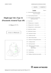
INSTALLATION/OPERATING INSTRUCTIONS R Model TSC/TSR Pressure Model COC Pressure Two Stage Set Point Control Ranges 0 - 30, 0 - 100, and 0 - 200 psi Output 1 Digital display reads sensor value constantly Red light indicates output status Push this button to display the set points, differential and offset Black Black Red Red Output 2 OUTPUT = Set Point 1 UP = Set Point 2 = Differential = Offset PRESS TO READ DOWN Push these buttons to adjust the settings = Shorted Sensor = Open Sensor SENSOR _ 24VAC Blue Blue + To power with 120VAC connect to these wires To power with 24VAC connect to these two terminals Black Red Wire to 0-30, 0-100 or 0-200 psi pressure transducer observing the polarity Warning: This Heat-Timer control is strictly an operating control; it should never be used as a primary limit or safety control. All equipment must have its own certified limit and safety controls required by local codes. The installer must verify proper operation and correct any safety problems prior to the installation of this Heat-Timer control. LIMITED ONE YEAR WARRANTY This Heat-Timer device was thoroughly tested for defects and workmanship before leaving our factory. We do warrant the equipment to be free of defects under normal use for a period of one year from the date of installation. Transportation charges for factory repairs must be prepaid. Damage to the Heat-Timer device or any of its components due to misuse, abuse, improper installation, or caused by power failures, fire, flood, or lightning are not covered by this warranty. The company assumes no liability for indirect or consequential damages of any nature. This Heat-Timer warranty applies only to the original purchaser/user, is not assignable or transferable, and does not cover damage to the device occurring in shipment. Any service, repairs, modifications or alterations to the unit not expressly authorized by the company will invalidate the warranty. This warranty is in lieu of all other warranties expressed or implied. 1 INSTALLATION Mounting the Controller The Digi-Span is designed to mount on a 1900 (4x4) electrical box. If the Digi-Span is to be panel mounted, or if additional room is needed for wiring, an extension skirt is available*. Locate the Digi-Span in a convenient location near the unit to be controlled. Mount the Digi-Span away from excessive heat or cold. Ambient operating temperature is from 20 to 120°F. After completing all the wiring connections (see below) use the two screws provided to mount the Digi-Span to the 1900 box. Installing the Pressure Sensor Attach a 1/4 brass isolation tube (pigtail) to the steam header. Screw the pressure sensor to the pigtail. The sensor has 1/4"NPT tapered threads. The BLACK and RED sensor wires can be extended up to 500 by splicing with 18 gauge shielded wire. Any other sensor wires (green, white, or shield) and the tube are not used and do not need to be extended. Do not run wires in conduit with line voltage. The Digi-Span will operate based on the pressure it reads at the sensor location. Therefore, select a sensor location which is representative of the entire system. Wiring the Sensor The BLACK wire from the pressure transducer should be connected to the terminal marked SENSOR -. The RED wire from the pressure transducer should be connected to the terminal marked SENSOR +. The transducer wires can also be connected to the back of the Digi-Span using the Rear Wire connector*. Connect the BLACK sensor wire to yellow Rear Wire and the RED sensor wire to the orange Rear Wire. Wiring the Power - Digi-Span can use either 120VAC or 24VAC 120VAC Attach line voltage to the two blue wires extending from the back of the Digi-Span. Use wire nuts, or wrap the connections with electrical tape. Class 1 voltages must enter the enclosure through a different opening from any Class 2 wiring. 24VAC Use a dedicated transformer with at least a 5VA output. Bring 24VAC to the two screws on the front of the Digi-Span marked 24VAC. 24VAC can also be connected to the rear of the Digi-Span using the Rear Wire connector*. Connect the 24VAC to the violet and gray Rear Wires. WARNING The Digi-Span can accept only one source of power: 120VAC or 24VAC. If more than one power source is applied, the unit may be damaged. Wiring the Output The Digi-Span has two SPST (single pole single throw) relay outputs rated at 10A, 1/8 HP. The outputs are dry contacts only. They do not source any power. The Black wires are the N.O. (normally open) contacts for Output 1. The Red wires are the N.O. (normally open) contacts for Output 2. If the outputs are carrying any Class 1 voltages, then they must enter the enclosure through a different opening from any Class 2 wiring. * The Optional Mounting Kit includes the extension skirt, the Rear Wire connector with four wires (orange, yellow, violet, and gray) and an input terminal cover. Order separately as HT #908520. 2 Setting the Operating Modes Whenever the Digi-Span is powered up, it will display the software version number and then the current operating modes. Each display will remain on the screen approximately 5 seconds. If the modes are correct, there is no need to make any adjustments. Once the modes have been set for a particular application, they will be retained in memory and will not need to be reset. Note that if you do change an operating mode, you will need to reset the set points, differential and offset. An operating mode can only be changed when it is being displayed in the start-up sequence. To restart the sequence it is necessary to remove power to the Digi-Span and then power it again. Set the operating modes as described in sequence below: 30, 100, or 200 - Pressure Range If the display shows 30 then the range will be from 0 to 30 psi and the display will be in 0.5psi increments. If the display shows 100 or 200, the range will be 0 to 100psi or 0 to 200psi and will display in one pound increments. To change the range, hold down the center button while pushing either the UP or DOWN button to toggle between ranges. When the range is selected, release the buttons and wait approximately 5 seconds. H or C - Heating or Cooling (TSC/TSR only) If the display shows H then the Digi-Span will be in a heating mode. The relays will close when the pressure is below the set point (see Example on pg.6) If the display shows C then the Digi-Span will be in a cooling mode. The relays will close when the pressure is above the set point. To change the mode, hold down the center button while pushing either the UP or DOWN button to toggle between the displays of H and C. When the correct heating or cooling mode is selected, release the buttons and wait approximately 5 seconds. TSC or TSR - Fixed or Rotating Lead Stage (TSC/TSR only) If the display shows TSC the lead stage will not rotate. Set Point 1 will always control the Black output wires, and Set Point 2 will always control the Red output wires. If the display shows TSR, the lead stage will rotate every day to provide more even wear on the units being controlled; that is, Set Point 1 will control the Black output wires one day, and the Red output wires the next day. If any changes were made to the operating modes, the display will flash. Then the Digi-Span will display the sensor pressure. TYPICAL WIRING DIAGRAM SENSOR BLACK OUTPUT 1 POWER HEATER or CHILLER OUTPUT 1 OUTPUT 2 POWER HEATER or CHILLER OUTPUT 2 BLACK RED RED WARNING 24 VAC or wire 120VAC to rear transformer (blue wires) 3 The Digi-Span can accept only one source of power: 120VAC or 24VAC. If more than one power source is applied, the unit may be damaged. COC OPERATION Set Point 1 Set Point 1 controls when Output 1 is energized or open as shown in the Example. When Output 1 is energized, the Black output wires will be continuous. When Output 1 is open, the Black output wires will be open. To adjust Set Point 1, use the following steps: 1. Digi-Span should be displaying sensor pressure. 2. Press the center button and release it. The display will change to show SP1. Wait 2 seconds or press the UP or DOWN button and the set point will be displayed. 3. Press and hold either the UP or DOWN button until the desired set point is displayed. NOTE: Set Point 1 can not be set below Set Point 2. If pressing the DOWN button does not lower Set Point 1, it may be necessary to lower Set Point 2 (see below). 4. Wait approximately 10 seconds. If the set point was changed, the display will flash. Then the Digi-Span will return to displaying the sensor pressure. (If you dont want to wait 10 seconds, press the center button once for Set Point 2, twice for Differential, three times for Offset or four times to display sensor pressure.) SET POINT and DIFFERENTIAL EXAMPLE Set Point 1 Set Point 2 Differential 60psi 40psi 2psi OUTPUT 1 - BLACK On a rise to 60psi Stage 1 will Energize Light will Flash -------------------------------------------------On a drop to 58psi Stage 1 will Open Light is OFF Set Point 2 Set Point 2 controls when Output 2 is energized or open as shown in the Example. When Output 2 is energized, the Red output wires will be continuous. When Output 2 is open, the Red output wires will be open. To adjust Set Point 2, use the following steps: 1. Digi-Span should be displaying sensor pressure. 2. Press the center button twice and release it. The display will change to show SP2. Wait 2 seconds or press the UP or DOWN button and the set point will be displayed. 3. Press and hold either the UP or DOWN button until the desired set point is displayed. NOTE: Set Point 2 can not be set above Set Point 1. If pressing the UP button does not increase Set Point 2, it may be necessary to raise Set Point 1 (see above). 4. Wait approximately 10 seconds. If the set point was changed, the display will flash. Then the Digi-Span will return to displaying the sensor pressure. (If you dont want to wait 10 seconds, press the center button once for Differential, twice for Offset, or three times to display sensor pressure.) OUTPUT 2 - RED On a drop to 38psi Stage 2 will Energize Light is ON -------------------------------------------------On a rise to 40psi Stage 2 will Open Light is OFF 4 Differential The differential controls how many psi the system can fluctuate around the set points. It is used to prevent short cycling of the units being controlled. Output 1 will energize when the sensor pressure rises to Set Point 1. Output 1 will open when the pressure falls to the Set Point 1 minus the differential (see Example on opposite page). Output 2 will energize when the sensor pressure falls to Set Point 2 minus the differential. Output 2 will open when the pressure rises to Set Point 2 (see Example opposite page). To set the differential, use the following steps: 1. Digi-Span should be displaying sensor pressure. 2. Press and release the center button three times. The display will change to show dIF. Wait 2 seconds or press the UP or DOWN button and the differential will be displayed. 3. Press and hold either the UP or DOWN button until the desired differential is displayed. 4. Wait approximately 10 seconds. If the differential was changed, the display will flash. Then the Digi-Span will return to displaying the sensor pressure. (If you dont want to wait 10 seconds, press the center button once for Offset or twice for the sensor pressure to be displayed immediately.) Offset The offset value calibrates the sensor pressure reading by the number of pounds selected. To adjust the offset, use the following steps: 1. The Digi-Span should be displaying sensor pressure. 2. Press the center button four times and release it. The display will change to show OFF. Wait 2 seconds or press the UP or DOWN button and the offset will be displayed. 3. Press and hold either the UP or DOWN button until the desired offset is displayed. 4. Wait approximately 10 seconds. If the offset was changed, the display will flash and then show the corrected sensor pressure. (If you dont want to wait, press the center button once.) OUTPUT Light Indication The red OUTPUT light indicates which stage is active. When the red light is: OFF - Neither output stage is active. Both the Black and Red wires are open. FLASHING - Output 1 is energized. The Black output wires are continuous. ON - Output 2 is energized. The Red output wires are continuous. 5 TSC/TSR OPERATION SET POINT and DIFFERENTIAL EXAMPLE Set Point 1 Set Point 1 controls when Stage 1 is energized or open as shown in the Example. TSC mode - Stage 1 controls the Black output wires (see pg. 3). TSR mode - For the first 12 hours of operation, Stage 1 controls the Black output wires. For the next 24 hours, Stage 1 controls the Red output wires. Then the control will switch back to Black and will switch again every 24 hours. To adjust Set Point 1, use the following steps: 1. Digi-Span should be displaying sensor pressure. 2. Press the center button and release it. The display will change to show SP1. Wait 2 seconds or press the UP or DOWN button and the set point will be displayed. 3. Press and hold either the UP or DOWN button until the desired set point is displayed. 4. Wait approximately 10 seconds. If the set point was changed, the display will flash. Then the Digi-Span will return to displaying the sensor pressure. (If you dont want to wait 10 seconds, press the center button once for Set Point 2, twice for Differential, three times for Offset or four times to display sensor pressure.) Set Point 1 Set Point 2 Differential HEATING MODE On a drop to 58psi Stage 1 will Energize Light will Flash On a further drop to 48psi Stage 2 will Energize Light is ON -------------------------------------------------On a rise to 50psi Stage 2 will Open Light will flash On a further rise to 60psi Stage 1 will Open Light is OFF COOLING MODE Set Point 2 Set Point 2 controls when Stage 2 is energized or open as shown in the Example. TSC mode - Stage 2 controls the Red output wires (see pg. 3). TSR mode - For the first 12 hours of operation, Stage 2 controls the Red output wires. For the next 24 hours, Stage 2 controls the Black output wires. Then the control will switch back to Red and will switch again every 24 hours. To adjust Set Point 2, use the following steps: 1. Digi-Span should be displaying sensor pressure. 2. Press the center button twice and release it. The display will change to show SP2. Wait 2 seconds or press the UP or DOWN button and the set point will be displayed. 3. Press and hold either the UP or DOWN button until the desired set point is displayed. 4. Wait approximately 10 seconds. If the set point was changed, the display will flash. Then the Digi-Span will return to displaying the sensor pressure. (If you dont want to wait 10 seconds, press the center button once for Differential, twice for Offset or three times to display sensor pressure.) NOTE: Set Point 1 does not need to be set above Set Point 2. Either set point can be any value in the operational range. See page 3 to set either the Heating or the Cooling mode. 60psi 50psi 2psi On a rise to 50psi Stage 2 will Energize Light will Flash On a further rise to 60psi Stage 1 will Energize Light is ON -------------------------------------------------On a drop to 58psi Stage 1 will Open Light will flash On a further drop to 48psi Stage 2 will Open Light is OFF TSC Stage 1 controls Black output wires Stage 2 controls Red output wire TSR Outputs rotate 12 hours after initial powerup and every 24 hours thereafter 6 Differential The differential controls how many pounds the system can fluctuate around the set points. It is used to prevent short cycling of the units being controlled. In the heating mode, a stage will energize when the sensor pressure falls to the set point minus the differential. The stage will open when the pressure rises to the set point (see Example on opposite page). In the cooling mode, a stage will energize when the sensor pressure rises to the set point. The relay will open when the pressure falls to the set point minus the differential. To set the differential, use the following steps: 1. Digi-Span should be displaying sensor pressure. 2. Press and release the center button three times. The display will change to show dIF. Wait 2 seconds or press the UP or DOWN button and the differential will be displayed. 3. Press and hold either the UP or DOWN button until the desired differential is displayed. 4. Wait approximately 10 seconds. If the differential was changed, the display will flash. Then the Digi-Span will return to displaying the sensor pressure. (If you dont want to wait 10 seconds, press the center button once for Offset or twice to display sensor pressure immediately.) Offset The offset value calibrates the sensor pressure reading by the number of pounds selected. To adjust the offset, use the following steps: 1. The Digi-Span should be displaying sensor pressure. 2. Press the center button four times and release it. The display will change to show OFF. Wait 2 seconds or press the UP or DOWN button and the offset will be displayed. 3. Press and hold either the UP or DOWN button until the desired offset is displayed. 4. Wait approximately 10 seconds. If the offset was changed, the display will flash and then show the corrected sensor pressure. (If you dont want to wait, press the center button once.) OUTPUT Light Indication The red OUTPUT light indicates how many stages are active at any given time. When the red light is: OFF - Neither output stage is active. Both the Black and Red wires are open. FLASHING - One output stage is active. Either the Black or the Red wires are continuous, but not both. ON - Both output stages are active. Both the Black and Red wire are continuous. 7 TROUBLESHOOTING No Display: Check the power to the Digi-Span. The Digi-Span can run off any of the power sources described on page 2. Turn the power off and back on. OPN Display: The Digi-Span does not see a sensor connected. Check the wires are continuous from the sensor to the DigiSpan controller. Then follow the procedure for Incorrect Pressure Display. SHT Display: The Digi-Span sees a short across the input terminals. If you remove the sensor wires from the Digi-Span terminals, the display should change to read OPN. If the display does not change to OPN, the Digi-Span may be damaged. Incorrect Pressure Display: Remove the wires from the SENSOR screws. The display should change to read OPN. If it doesnt, the Digi-Span may be damaged. Use a voltmeter to measure across the SENSOR screws. There should be at least 24VDC across the two terminals. If there isnt, the Digi-Span may be damaged. Finally, reconnect the sensor with a mA meter in series with one sensor wire. The mA reading should correspond to the chart below. You can use the Offset value (see pg. 5 or 7) to make small adjustments to the pressure reading. OUTPUT Red Light does not indicate desired stages are active: Check the set points and differential values. In a heating application, the stage will not come on until the pressure drops below the set point minus the differential. In a cooling application, the stage will come on when the pressure rises to the set point. (see Examples on pgs. 4 and 6). Digi-Span does not activate the output: First check the OUTPUT light to see which stages should be active. If the OUTPUT light is OFF, no stages should be running. If the OUTPUT light is flashing or on, check page 4 for a COC or page 6 for a TSC/TSR to see which output wires should be continuous. Remove all connections to the Black and Red output wires. Check the appropriate wires for continuity. If the wires are continuous, the Digi-Span is working properly. Check the unit the Digi-Span is controlling to determine why it is not running. mA 30 PSI 4 4 .0 8 4 .1 6 4 .4 4 .5 6 4 .8 5 .0 6 5 .6 6 .1 3 6 .4 6 .6 7 .2 8 .8 1 0. 4 12 1 3. 6 1 5. 2 1 6. 8 1 8. 4 20 0 100 PSI 200 PSI 0 1 0 1 2 5 1 2 3 4 5 6 9 12 15 18 21 24 27 30 5 10 10 20 15 30 20 30 40 50 60 70 80 90 1 00 40 60 80 10 0 12 0 14 0 16 0 18 0 20 0 For Technical Help or Additional Product Information contact: Heat-Timer Corporation 20 New Dutch Lane Fairfield, NJ 07004 Phone (973) 575-4004 Fax (973) 575 -4052 http://www.heat-timer.com 8 HT 059218-00