1
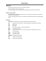
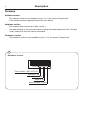
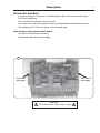
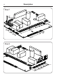
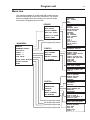
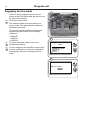
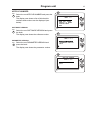
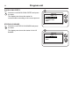
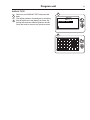
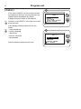
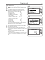
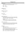
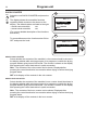
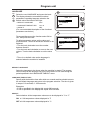
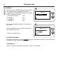
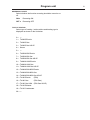
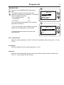
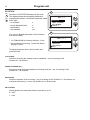
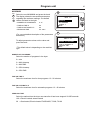
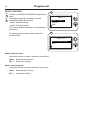
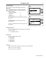
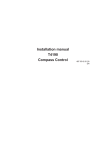
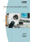
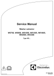
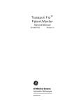
Service manual
Compass Control
Tumble dryers
T4130, T4190
487 05 40 81/EN
08.36
Contents
Contents
Safety rules . . . . . . . . . . . . . . . . . . . . . . . . . . . . . . . . . . . . . . . . . . . . . . . . 5
Description . . . . . . . . . . . . . . . . . . . . . . . . . . . . . . . . . . . . . . . . . . . . . . . . 7
Generel . . . . . . . . . . . . . . . . . . . . . . . . . . . . . . . . . . . . . . . . . . . . . . . 7
Versions . . . . . . . . . . . . . . . . . . . . . . . . . . . . . . . . . . . . . . . . . . . . . . . 8
Connector numbers . . . . . . . . . . . . . . . . . . . . . . . . . . . . . . . . . . . . . . 9
Usage of the connections . . . . . . . . . . . . . . . . . . . . . . . . . . . . . . . . 11
Program unit . . . . . . . . . . . . . . . . . . . . . . . . . . . . . . . . . . . . . . . . . . . . . . 13
Menu tree. . . . . . . . . . . . . . . . . . . . . . . . . . . . . . . . . . . . . . . . . . . . . 13
Engaging service mode . . . . . . . . . . . . . . . . . . . . . . . . . . . . . . . . . . 14
Service. . . . . . . . . . . . . . . . . . . . . . . . . . . . . . . . . . . . . . . . . . . . . . . 16
Config 1 . . . . . . . . . . . . . . . . . . . . . . . . . . . . . . . . . . . . . . . . . . . . . . 22
Config 2 . . . . . . . . . . . . . . . . . . . . . . . . . . . . . . . . . . . . . . . . . . . . . . 29
Troubleshooting. . . . . . . . . . . . . . . . . . . . . . . . . . . . . . . . . . . . . . . . . . . . 41
Generel . . . . . . . . . . . . . . . . . . . . . . . . . . . . . . . . . . . . . . . . . . . . . . 41
Error codes overview. . . . . . . . . . . . . . . . . . . . . . . . . . . . . . . . . . . . 42
Check list - error codes related to overheating . . . . . . . . . . . . . . . . 43
E03 - E24. . . . . . . . . . . . . . . . . . . . . . . . . . . . . . . . . . . . . . . . . . . . . 44
3
Safety rules
Safety rules
Programming is only to be carried out by qualified personnel.
High voltage on the printed circuit board.
IMPORTANT SERVICE NOTE!
Continuity and resistance measurements suggested by the procedures in this
manual require that power to the dryer be disconnected, and that the device
whose resistance is being measured be disconnected from all circuits that
might affect the accuracy of the measurement.
Note! It is very important that the board
is protected from static electricity
Remember!
• Always use an earthed wrist strap.
• Without the antistatic wrapping the board is unprotected.
• Keep all subjects away from the board which can cause static electricity.
• Subjects like plastic, foam plastic, nylon, or cellophane wrapping are
all big dischargers of static electricity.
• Static electricity can not always be felt, heard or seen.
• Board components can be damaged by static electricity under 100V.
• Static electricity can not be felt, heard or seen till the voltage reaches
2500V.
5
Description
Generel
From factory, the dryer has been set to specific values for:
Time, temperature, cooling, reversing, etc.
The above parameters are changeable by reprogramming the Selecta Control PCB.
Selecta Control PCB
The PCB Module is located under the top cover on the front of the machine, see the service
manual for the specific dryer.
In order to reprogramme the dryer it is necessary to switch the print board into programming
mode.
Glossary
Auto Stop The tumble dryer stops automatically when the clothes are dry.
AHL
Apartment House Laundry - Communal laundries / Housing block laundries.
GN
Natural gas
LPG
Bottle gas
OPL
On Premises Laundry - Institutional laundries.
PCB
Printed Circuit Board.
RMC
Residual Moisture Control - The tumble dryer has residual moisture control.
CP
Central Payment
CMD
Coin Meter Double
CMS
Coin Meter Single
CMSNCB Coin Meter No Coin Box
ESS
Electrolux Single System
PCR
Prepared for Card Reader
7
Description
8
Versions
Software version
The software version is only readable in menu 1-3-1, see section "Program Unit"
If the software has been upgraded a label has been affixed.
Hardware version
The hardware data is printed on a label, see fig. 1.
The label is affixed on the print board which is facing downward towards the drum. The label
is only visible when the print board is demounted.
Parameter version
The parameter version is only readable in menu 1-3-2, see section "Program Unit"
1
Hardware version
487027927002005450050
Part number = 487 02 79 27
Revision = 00
Year = 2005
Week = 45
Serial number = 0050
Description
9
Connector numbers
In the error analyses in the section "Troubleshooting" later in this manual connections
P1-P23 are mentioned.
The P-numbers are printed on the print board.
The usage of the connections appears from the wiring diagrams supplied with the dryer.
The positionings of P1-P23 are shown on the following page.
High voltage on the printed circuit board
Do not touch the printed circuit board.
The shaded areas indicate high voltage.
1
See view 1
next page
See view 2
next page
Warning!
The shaded areas indicate high voltage
Description
10
View 1
P22
P23
P5
P4
P3
P2
P1
P21
P19
P16
P18
P17
Seeview 1
View 2
P8
P9
P7
P6
P10
P11
P12
P13
P14
P15
Description
Usage of the connections
It is possible to connect following features to the PCB.
P1
Motor control
P2
Vacuum and fan input
P3
Power on
P4
Power out
P5
Heat control
P6
Els-Network
P7
Els-Network
P8
18V AC out
P9
18v AC in
P10
RMC
P11
RS 232 - internal use (incl. 24V DC)
P12
RS 232 - programme
P13
Data bus (incl. 24V DC)
P14
Data bus (incl. 24V DC)
P15
Gas control
P16
Rotary (Compass Control)
P17
Display (Compass Control)
P18
Temperature sensor and filter input
P19
External gas reset and service switch
P20
Discount and external error (option)
P21
Free drying
P22
CP, CMS, CMSNCB, ESS, PCR
P23
CMD
11
Program unit
13
Menu tree
The machine software is constructed with menus that are
structured according to the menu tree below. The menus
become available when the machine is in service mode,
see section "Engaging service mode".
SERVICE
ACTIVATE OUTPUTS
SHOW INPUTS
ARTICLE NUMBER
SHOW COM. PORTS
STATUS I/O BOARD
DISPLAY TEST
See programming manual
MAIN MENU
SERVICE
PARAMETER PROGR.
STATISTICS
CONFIG. 1
CONFIG. 2
COIN VALUE
QUICK START BUTTONS
ADJUST DISPLAY
RESET
See programming manual
CONFIG 1
USER INTERFACE
SHOW COUNTER
LANGUAGE
SPECIAL CONTROL
I/O ADDRESS
HEAT
DIRECTION
EXT. SIGNAL
FAN
DRUM
DOOR CLOSED
VACUUM
EXTERNAL INPUT
PRICE REDUCTION
FILTER CLOSED
OVERHEAT
GAS INPUT
FAN OVERHEAT
DRUM OVERHEAT
FREE DRY
COIN 1
COIN 2
QUICK START 1
QUICK START 2
ANALOG
SOFTWARE VERSION
PARAMETER VERSION
BUTTON CLICK
STANDBY VALUE
STANDBY VALUE BLINKS
FINAL BLINKS
TIMEOUT DISPLAY SEC
TIMEOUT END BUZZ SEC.
SHOW TIME
SHOW TEMP
DEFAULT TEMP
SHOW COIN COUNTER
SHOW HOUR COUNTER
DEFAULT LANGUAGE
LANGUAGE TIMEOUT SEC.
SHOW °F
REVERSING ON/OFF
TYPE OF HEATING
PAYMENT SETTING
CONTROL PANEL
PROGRAMS
CONFIG 2
CONFIG PCB
TEMPERATURE
ROTATION
MAXIMUM
RESET COUNTERS
ELS NETWORK
See programming manual
See programming manual
See programming manual
See programming manual
INLET TEMPERATURE
HYSTERESIS
AUTOSTOP
CLOCKWISE
PAUSE BETWEEN REV.
REVERSING
ANTICREASE
NUMBER OF PROGRAMS
TIME ON TIME P.
TIME ON AUTOMATIC P.
PENDLING TIME
RESET SERVICE HOURS
RESET TRIP RUN HOURS
MACHINE ADDRESS
BAUD RATE
TIME OUT
DRYER TYPE
CONFIG. 3
Program unit
14
Engaging service mode
Service mode is engaged using the service
switch on the CPU board under the top cover on
the front of the machine.
Fig.
1
Press the service button.
1
A
The machine software will now switch to its
service mode. The display lists the submenus
available in this mode.
This service manual describes functions and
programming instructions for the following
submenus:
• SERVICE
• CONFIG 1
• CONFIG 2
Fig.
2
Fig.
3
2
For other submenus, please refer to the
programming manual.
MAIN MENU
MENU 1
SERVICE
PARAMETER PROGR.
STATISTICS
CONFIG 1
CONFIG 2
To save changes to the machine's memory they
must be confirmed in a menu that is displayed
automatically whenever a change has been
made.
6204
3
NEW VALUE IS:
SERVICE
ARE YOU SURE?
YES
6204
Program unit
15
Special modes for PCB
SELECTA MODE
There is a possibility that the CPU board is
programmed to use the Selecta display.
Fig.
4
4
SELECTA CO N TRO L
Selecta mode: The Compass display is lit and the
Selecta display shows "0_ _".
In order to engage Compass service mode keep
pressing the service button when the power is
turned on.
BOOT MODE
There is a possibility that the CPU board is in
Boot mode.
In Boot mode new software for the CPU board
can be downloaded. A special PC-program is
required.
Boot mode: All 4 LEDs for the choice of
temperature is lit and the display is turned off.
Fig.
5
In order to engage the CPU board in boot mode it
must already be engaged in service mode and
then the gas reset button B must be pressed. To
leave boot mode press the gas reset button
again or download new software.
5
B
Program unit
16
Service
6
The service program is used to facilitate troubleshooting the machine. Using this programe it is
possible to:
MAIN MENU
MENU 1
SERVICE
PARAMETER PROGR.
STATISTICS
CONFIG 1
CONFIG 2
• control the machine functions individually
• control the sensor signals to the CPU board
• check the communication in the machine
control system
6204
• check the display
Fig.
6
Engage the service mode and select the row
SERVICE in the main menu and press the knob.
7
SERVICE
MENU 1-1
The display now shows the different submenus in
the service program:
Fig.
7
ACTIVATE OUTPUTS
SHOW INPUTS
ARTICLE NUMBER
SHOW COM. PORTS
STATUS I/O BOARD
• ACTIVATE OUTPUTS
• SHOW INPUTS
• ARTICLE NUMBER
• SHOW COM. PORTS
• STATUS I/O BOARD
• DISPLAY TEST
Select menu and press the knob.
6204
Program unit
ACTIVATE OUTPUTS
Fig.
8
Select the row ACTIVATE OUTPUTS and press
the knob.
17
8
SERVICE
MENU 1-1
The display now shows the functions (outputs)
which can be activated:
ACTIVATE OUTPUTS
SHOW INPUTS
ARTICLE NUMBER
SHOW COM. PORTS
STATUS I/O BOARD
• HEAT
• DIRECTION
• EXT SIGNAL
6204
• FAN
• DRUM
Fig.
9
Select function and press the knob.
ACTIVATE OUTPUTS
MENU 1-1-1
9
HEATSHOW INPUTS
DIRECTION
EXT SIGNAL
FAN
DRUM
6204
Program unit
18
SHOW INPUTS
Fig.
10
Fig.
11
10
Select the row SHOW INPUTS and press the
knob.
SERVICE
MENU 1-2
The display now shows the sensor signals
(inputs) which can be controlled:
SHOW INPUTS
ARTICLE NUMBER
SHOW COM. PORTS
STATUS I/O BOARD
DISPLAY TEST
• DOOR CLOSED
• VACUUM
• EXTERNAL INPUT
6204
• PRICE REDUCTION
• FILTER CLOSED
• OVERHEAT
11
• GAS INPUT
ACTIVATE OUTPUTS
MENU 1-2-1
• FAN OVERHEAT
• DRUM OVERHEAT
DOOR CLOSED
VACUUM
EXTERNAL INPUT
PRICE REDUCTION
FILTER CLOSED
• FREE DRY
• COIN 1
• COIN 2
• QUICK START 1
• QUICK START 2
• ANALOG
Select function and press the knob.
More inputs can be activated simultaneously.
6204
Program unit
ARTICLE NUMBER
Fig.
12
Select the row ARTICLE NUMBER and press the
knob.
19
12
SERVICE
MENU 1-3
The display now shows a list of which article
numbers and versions can be displayed (see
below):
SOFTWARE VERSION
Fig.
13
Select the row SOFTWARE VERSION and press
the knob.
The display now shows the software version.
ARTICLE NUMBER
SHOW COM. PORTS
STATUS I/O BOARD
DISPLAY TEST
EXIT
6204
13
ARTICLE NUMBER
MENU 1-3-1
PARAMETER VERSION
Fig.
14
SOFTWARE VERSION
PARAMETER VERSION
EXIT
Select the row PARAMETER VERSION and
press the knob.
The display now shows the parameter version.
6204
14
ARTICLE NUMBER
MENU 1-3-2
PARAMETER SOFTWARE
EXIT
6204
Program unit
20
SHOW COM. PORTS
Fig.
15
15
Select the row SHOW COM. PORTS and press
the knob.
SERVICE
MENU 1-4
The display now shows the status for
communication according to the current protocol.
STATUS I/O BOARD
Fig.
16
SHOW COM. PORTS
STATUS I/O BOARD
DISPLAY TEST
EXIT
6204
Select the row STATUS I/O BOARD and press
the knob.
The display now shows the status for the I/O
BOARD
16
SERVICE
MENU 1-5
STATUS I/O BOARD
DISPLAY TEST
EXIT
6204
Program unit
21
DISPLAY TEST
Fig.
17
Fig.
18
Select the row DISPLAY TEST and press the
knob.
17
SERVICE
MENU 1-6
The display shows a checked grid for checking
that all segments in the display are intact. By
turning the knob two different grids are shown.
Press the knob to return to the previous menu.
DISPLAY TEST
EXIT
6204
18
6204
Program unit
22
CONFIG 1
19
In the menu CONFIG 1 all the functions as well
as parameters which the service personnel can
change without a password are shown.
MAIN MENU
MENU 4
CONFIG 1
CONFIG 2
COIN VALUE
QUICK START BUTTONS
ADJUST DISPLAY
Engage the service mode on the machine.
Fig.
19
Select the row CONFIG 1 in the main menu and
press the knob.
In the display following submenus are now
shown:
Fig.
• USER INTERFACE
20
• SHOW COUNTER
6204
20
• LANGUAGE
CONFIG 1
MENU 4-1
• SPECIAL CONTROL
• I/O ADDRESS
USER INTERFACE
SHOW COUNTER
LANGUAGE
SPECIAL CONTROL
I/O ADDRESS
Select a submenu and press the knob.
6204
Program unit
USER INTERFACE
Fig.
21
Fig.
22
23
21
Select the row USER INTERFACE and press the
knob.
CONFIG 1
MENU 4-1
The display shows the accessible functions/
parameters regarding the user interface - the
default values are listed to the right:
• BUTTON CLICK
• STANDBY VALUE
• STANDBY VALUE BLINKS
• FINAL BLINKS
• TIMEOUT, DISPLAY, SEC
• TIMEOUT, END BUZ. SEC
OFF
00
OFF
ON
12 x 10
6204
22
10
• SHOW TIME
OFF
• SHOW TEMP
OFF
• DEFAULT TEMP
USER INTERFACE
SHOW COUNTER
LANGUAGE
SPECIAL CONTROL
I/O ADDRESS
USER INTERFACE
MENU 4-1-1
BUTTON CLICK
STANDBY VALUE
STANDBY VALUE BLINKS
FINAL BLINKS
TIMEOUT, DISPLAY, SEC
0
(For a more detailed description of the functions/
parameters see the following pages.)
6204
Fig.
23
To connect/disconnect the functions select ON or
OFF and press the knob.
23
To adjust parameter values set the value and
press the knob. The arrow shows the number to be
adjusted.
STANDBY VALUE
• Turn the knob clockwise to set the number
between 0 and 9.
000
• Turn the knob anti-clockwise to move to the next
column. Turn the knob clockwise to set the value
etc.
6204
Program unit
24
BUTTON CLICK
Select whether the machine should give a sound for each new
position when the knob is turned and pressed in.
ON =
Sound
OFF =
No sound
STANDBY VALUE
Not yet in use
STANDBY VALUE BLINKS
Not yet in use
FINAL BLINKS
Not yet in use
TIMEOUT, DISPLAY, SEC
Specify with the knob the time after which the machine should
reset a program selection that has not started. The time is given
in steps of 10 seconds; 0 - 255 x 10 seconds.
Examples:
• if 030 is specified in the display this equals 300 seconds
• if 220 is specified in the display this equas 2200 seconds.
TIMEOUT, END BUZ, SEC
Specify with the knob the time during which the buzzer should
sound at the end of the program unless the machine is turned
off manually. The time is given in seconds; 0 - 255.
SHOW TIME
(RMC and AHL only)
Select whether the calculated remaining drying time is to be
shown on the display while the program is in progress.
ON = The calculated time remaining of the program is shown
on the display while a drying program is an progress.
OFF =
No time is displayed in the display window.
Program unit
SHOW TEMP
Select if the current drying temperature in the drum is to be shown in the
display during the ongoing drying program.
ON = The drying temperature is to be shown
OFF = No drying temperature to be shown in the display
DEFAULT TEMP
Select the default drying temperature in the drum:
0 = No temperature
No default temperature is selected and therefore a temperature must be selected after
every program selection.
1 = High temperature
After a program has been selected the dryer
starts automatically on high temperature unless
another temperature is selected
2 = Medium temperature
After a program has been selected the dryer
starts automatically on medium temperature
unless another temperature is selected
3 = Low temperature
After a program has been selected the dryer
starts automatically on low temperature unless
another temperature is selected
4 = No heat
After a program has been selected the dryer
starts automatically on no heat unless another
temperture is selected
5 = Last temperature
After a program has been selected the dryer
starts automatically on the temperature last
selected.
25
Program unit
26
SHOW COUNTER
Fig.
24
Fig.
25
24
Select the row SHOW COUNTER and press the
knob.
CONFIG 1
MENU 4-2
The display shows the accessible functions
regarding which counters to be shown on the
display - the default values are listed to the right:
• SHOW COIN COUNTER
ON
• SHOW HOUR COUNTER
ON
(For a more detailed description of the functions
SHOW COUNTER
LANGUAGE
SPECIAL CONTROL
I/O ADDRESS
EXIT
6204
see below.)
25
To connect/disconnect the function select ON or
OFF and press the knob.
SHOW COUNTER
MENU 4-2-1
SHOW COIN COUNTER
SHOW HOUR COUNTER
EXIT
6204
SHOW COIN COUNTER
Select whether the contents of the machine’s coin counter should be shown in
the display window while a drying program is in progress or outside the drying
program without going into service mode. The counter is shown on the display
after pressing the control knob twice in quick succession.
ON = The contents of the coin counter can be shown. Displayed after
pressing the control knob twice in succession when drying or before the drying
program starts
OFF = No display of the contents in the coin counter
SHOW HOUR COUNTER
Select whether the contents of the machine’s hour counter should be shown in
the display window while a drying program is in progress or outside the drying
program without going into service mode. The counter is shown on the display
after pressing the control knob twice in quick succession.
ON = The contents of the hour counter can be shown. Displayed after
pressing the control knob twice in succession when drying or before the drying
program starts.
OFF = No display of the contents in the hour counter.
Program unit
LANGUAGE
Fig.
26
Fig.
27
27
26
Select the row LANGUAGE and press the knob.
The display shows the accessible functions/
parameters regarding language selection the
default values are listed to the right:
• DEFAULT LANGUAGE
N/A *
• LANGUAGE TIMEOUT SEC
12 x 10
• SHOW °F
OFF
(For a more detailed description of the functions/
parameters see below.)
CONFIG 1
MENU 4-3
LANGUAGE
SPECIAL CONTROL
I/O ADDRESS
EXIT
6204
27
To connect/disconnect the function select ON or
OFF and press the knob.
LANGUAGE
MENU 4-3-1
To adjust parameter values set the value and
press the knob. The arrow shows the number to be
adjusted.
DEFAULT LANGUAGE
LANGUAGE TIMEOUT SEC
SHOW °F
EXIT
• Turn the knob clockwise to set the number
between 0 and 9.
• Turn the knob anti-clockwise to move to the next
column. Turn the knob clockwise to set the value
etc.
6204
* There is no default value as the language is
selected when the machine is installed.
DEFAULT LANGUAGE
Select the language to be shown when the machine is started. The progam
unit will return to the language set here if the machine is not used during the
period specified in the LANGUAGE TIMEOUT menu.
LANGUAGE TIMEOUT SEC
Specify with the knob the time after which an unused machine should return to
the set default language and return to the program selection. The time is given
in steps of 10 seconds; 0 - 255 seconds.
Examples:
• if 030 is specified in the display this equals 300 seconds
• if 220 is specified in the display this equas 2200 seconds.
SHOW °F
Select whether all the temperature values are to be displayed in °C or °F
ON = 1 All temperature values displayed in °F
OFF = 0 All temperature values displayed in °C
Program unit
28
I/O ADDRESS
Fig.
28
Fig.
29
28
Select the row I/O ADDRESS and press the knob.
The display shows the accessible functions
regarding the I/O ADDRESS settings - the default
values are listed to the right:
• ACTIVATE I/O BOARD
OFF
• I/O BOARD 1
N/A *
• I/O BOARD 2
N/A *
• I/O BOARD 3
N/A *
(For a more detailed description of the functions
see below.)
CONFIG 1
MENU 4-5
I/O ADDRESS
EXIT
29
I/O ADDRESS
MENU 4-5-1
To connect/disconnect the function select ON or
OFF and press the knob.
ACTIVATE I/O BOARD
I/O BOARD 1
I/O BOARD 2
I/O BOARD 3
EXIT
* There is no default value
6204
ACTIVATE I/O BOARD
Activate the I/O board - it is very important to keep in mind that P13 and P14 can not be used
as ordinary I/O, eg. condensate pump T4130.
I/O BOARD 1-3
There is no value - press botton with above number on I/O board.
Program unit
CONFIG 2
29
30
In the menu CONFIG 2 all the functions as well
as parameters which the service personnel can
only change using a password are shown.
MAIN MENU
MENU 5
CONFIG 2
COIN VALUE
QUICK START BUTTONS
ADJUST DISPLAY
RESET TO FACTORY
Engage the service mode on the machine
Fig.
30
Select the row CONFIG 2 in the main menu and
press the knob.
6204
Fig.
31
In the display a password must be entered in
order to gain access to CONFIG 2
The password is 0001
31
PASSWORD
To enter the password:
• Turn the knob clockwise to set the number
between 0 and 9.
• Turn the knob anti-clockwise to move to the
next column. Turn the knob clockwise to set the
value etc.
Fig.
32
0000
6204
In the display following submenus are now
shown:
• CONFIG PCB
32
• TEMPERATURE
• ROTATION
CONFIG 2
MENU 5-1
• MAXIMUM
• RESET COUNTERS
CONFIG PCB
TEMPERATURE
ROTATION
MAXIMUM
RESET COUNTERS
• ELS NETWORK
Select a submenu and press the knob.
6204
Program unit
30
CONFIG PCB
Fig.
33
Fig.
34
33
Select the row CONFIG PCB and press the knob.
The display shows the accessible functions/
parameters regarding the configuration of the pcb
module:
CONFIG 2
MENU 5-1
CONFIG PCB
TEMPERATURE
ROTATION
MAXIMUM
RESET COUNTERS
• REVERSING ON/OFF*
• TYPE OF HEATING*
• PAYMENT SETTING*
• CONTROL PANEL*
• PROGRAMS*
(For a more detailed description of the functions/
6204
34
parameters see the following page.)
CONFIG PCB
MENU 5-1-1
To connect/disconnect the function select ON or
OFF and press the knob.
REVERSING ON/OFF
TYPE OF HEATING
PAYMENT SETTING
CONTROL PANEL
PROGRAMS
To adjust parameter values set the value and
press the knob.
6204
* There are no default values listed as the values
depend on the configuration of the machine.
Program unit
REVERSING ON/OFF
Select whether the function reversing should be turned on or
off.
ON =
Reversing ON
OFF =
Reversing OFF
TYPE OF HEATING
Select type of heating - both machine and heating type is
displayed as shown in the list below:
0 = --1 = T4300S Electric
2 = T4300S Gas
3 = T4300S Gas US/JP
4 = Steam
5 = --6 = T4250/4350 Electric
7 = T4250/4350 Gas
8 = T4250/4350 Gas US/JP
9 = T4900/41200 Electric
10 = T4900/41200 Gas
11 = T4900/41200 Gas US/JP
12 = T4290/4530/4650 Electric
13 = T4290/4530/4650 Gas
14 = T4290/4530/4650 Gas US/JP
15 = T4190 Electric
(PD9)
16 = T4190 Gas
(PD9 Gas)
17 = T4190 Gas USA (PD9 Gas US/JP)
18 = T4130 Exhaust
19 = T4130 Condensate
20 = ---
31
Program unit
32
PAYMENT SETTING
Select payment type - both no. and type is displayed as shown in the list below:
0 = --1 = 1 COIN NC
2 = 1 COIN NO
3 = 2 COIN NC
4 = 2 COIN NO
5 = CP TIME
6 = SINGLE SYSTEM
7 = CP COIN
8 = MASTER
9 = LM10
CONTROL PANEL
Select control panel type - both no. and type is displayed as shown in the list below.
0 = ---
Selecta mode
1 = COIN
Selecta mode
2 = AHL
Selecta mode
3 = OPL
Selecta mode
4 = COIN JP
Selecta mode
5 = TIME
Selecta mode
6 = COM COIN
Compass mode
7 = COM AHL
Compass mode
8 = COM OPL
Compass mode
PROGRAMS
Select program type - both no. and type is displayed as shown in the list below.
0 = COIN
1 = OPL RMC
2 = AHL RMC
3 = OPL AUTO
4 = AHL AUTO
Program unit
TEMPERATURE
Fig.
35
Fig.
36
33
35
Select the row TEMPERATURE and press the
knob.
CONFIG 2
MENU 5-2
The display shows the accessible functions/
parameters regarding the temperature - the default
values are listed to the right:
• INLET TEMPERATURE
N/A *
• HYSTERESIS
2 °C
• AUTOSTOP
N/A *
(For a more detailed description of the functions/
parameters see below.)
TEMPERATURE
ROTATION
MAXIMUM
RESET COUNTERS
ELS NETWORK
6204
36
* There are no default values listed as the values
depend on the configuration of the machine.
TEMPERATURE
MENU 5-2-1
INLET TEMPERATURE
HYSTERESIS
AUTOSTOP
EXIT
To adjust parameter values set the value and
press the knob.
6204
INLET TEMPERATURE
Select the inlet temperature, 80-180°C. However, all machines without inlet sensor = 0°C eg.
T4130.
HYSTERESIS
Select the hysteresis on the outlet temperature, 1-10°C.
AUTOSTOP
Select the outlet temperature the dryer must reach before it stops and the clothes are dry,
30-70°C - only on dryers with this function.
Program unit
34
ROTATION
Fig.
37
Fig.
38
37
Select the row ROTATION and press the knob.
The display shows the accessible parameters
regarding the rotation - the default values are listed
to the right:
• CLOCKWISE
5
• PAUSE BETWEEN REV.
3*
• REVERSING
5 **
• ANTICREASE
ON
(For a more detailed description of the functions
CONFIG 2
MENU 5-3
ROTATION
MAXIMUM
RESET COUNTERS
ELS NETWORK
CONFIG 3
6204
38
see further below.)
ROTATION
MENU 5-3-1
* On T4900/41200 the factory setting is 12 sec.
CLOCKWISE
PAUSE BETWEEN REV.
REVERSING
ANTICREASE
EXIT
** On machines w/reversing, 1 motor the factory
setting is 15 sec.
To adjust parameter values set the value and
press the knob.
6204
CLOCKWISE
Select for how long the rotation must be clockwise - only if reversing is ON.
Duration 01 - 99 minutes.
PAUSE BETWEEN REV.
Select how long the pauses between reversings must be - only if reversing is ON.
Duration 01 - 99 seconds.
REVERSING
Select the duration of the reversing - only if reversing is ON. Duration 01 - 99 minutes (on
machines w/reversing, 1 motor the duration is 01- 99 seconds).
ANTICREASE
Select whether the anticrease function must be on or off
0 = OFF
1 = ON
Program unit
MAXIMUM
Fig.
39
Fig.
40
35
39
Select the row MAXIMUM and press the knob.
The display shows the accessible parameters
regarding the maximum settings - the default
values are listed to the right:
• NUMBER OF PROGRAMS
0-9*
• TIME ON TIME P
90
• TIME ON AUTOMATIC P
90
• PENDLING TIME
20 - 255 *
(For a more detailed description of the parameters
CONFIG 2
MENU 5-4
MAXIMUM
RESET COUNTERS
ELS NETWORK
CONFIG 3
EXIT
6204
40
see below.)
MAXIMUM
MENU 5-4-1
To adjust parameter values set the value and
press the knob.
* The default value is depending on the machine
type
NUMBER OF PROGRAMS
TIME ON TIME P
TIME ON AUTOMATIC P
PENDLING TIME
EXIT
6204
NUMBER OF PROGRAMS
Select the number of programs in the dryer
0 = coin
2 = AHL Autostop
3 = AHL RMC
5 = OPL Autostop
9 = OPL RMC
TIME ON TIME P
Select the maximum time for time programs: 10 - 90 minutes
TIME ON AUTOMATIC P
Select the maximum time for automatic programs: 10 - 90 minutes
PENDLING TIME
Select the earliest time the dryer can start after it has been stopped: 20-255 seconds.
120 = Electric heated, steam heated
20 = Gas heated, Electric heated T4250/4350, T4300, T4190
Program unit
36
RESET COUNTERS
Fig.
41
Fig.
42
41
Select the row RESET COUNTERS and press the
knob.
CONFIG 2
MENU 5-5
The display shows the accessible functions
regarding resetting the counters:
RESET COUNTERS
ELS NETWORK
CONFIG 3
EXIT
• RESET SERVICE HOURS
• RESET TRIP RUN HOURS
(For a more detailed description of the parameters
see below.)
6204
42
To adjust parameter values set the value and
press the knob.
RESET COUNTERS
MENU 5-5-1
RESET SERVICE HOURS
RESET TRIP RUN HOURS
EXIT
6204
RESET SERVICE HOURS
Select this function in order to reset the service hours.
YES =
Reset the service hours
NO =
Cancel the resetting
RESET TRIP RUN HOURS
Select this function in order to reset the trip run hours.
YES =
Reset the trip run hours
NO =
Cancel the resetting
Program unit
ELS NETWORK
Fig.
43
Fig.
44
37
43
Select the row ELS NETWORK and press the
knob.
CONFIG 2
MENU 5-6
The display shows the accessible parameters
regarding ELS network - the default values are
listed to the right:
• MACHINE ADDRESS
0
• BAUD RATE
0
• TIME OUT
0
• DRYER TYPE
N/A *
(For a more detailed description of the parameters
ELS NETWORK
CONFIG 3
EXIT
6204
44
see below.)
ELS NETWORK
MENU 5-6-1
To adjust parameter values set the value and
press the knob.
* There is no default value as the dryer type is set
from factory
MACHINE ADDRESS
BAUD RATE
TIME OUT
DRYER TYPE
EXIT
6204
MACHINE ADDRESS
Select the number/address of the machine in the network.
0 = not in network
1 - 27 = available numbers
BAUD RATE
Select the communication speed.
0 = 38400 BAUD
1 = 2400 BAUD
2 = 9600 BAUD
3 = 38400 BAUD
TIME OUT
Select when the dryer must report a time out error: 0-99 seconds
CMIS = 10 sec. (error code E21)
LM10 = 90 sec. (error code E22)
(to be continued ...)
Program unit
38
(... continued)
DRYER TYPE
Select which type of machine the dryer is - this will be communicated to the computer:
1 = T4130
2 = T3190
3 = T3250
4 = T3350
5 = T3300/TD30•30
6 = T4290/TD30
7 = T4530/TD50
8 = T4650/TD75
9 = -------10 = T4250
11 = T4350
12 = T4900/TD100
13 = T41200/TD135
14 = T4300S/TD30x30S
15 = T4190
Program unit
CONFIG 3
Manufacturer use only.
39
Troubleshooting
41
General
The dryer is equipped with an automatic diagnostic system.
An error in the program or in the machine is indicated on the display by an error message
comprising an error code and a descriptive text. Whenever an error occurs, the dryer stops
operating.
ERROR
ERROR
E-18
E-18
THE
THE OUTPUT
OUTPUT
SENSOR
SENSOR HAS
HAS
DISCONNECTED
DISCONNECTED
Error analysis
A diagnostic procedure is provided for each error code. If an error has not been corrected after
the procedure, please contact the manufacturer for additional assistance.
Troubleshooting
42
Error codes overview
Error
code
Description
E 01
Option Not in use.
E 02
Option Not in use.
E 03
Inlet air - Sensor has short-circuited The thermistor element measuring the air
inlet temperature to the drum, or the wiring to the sensor has shorted.
E 04
Outlet air - Sensor has short-circuited The thermistor element measuring the air
outlet temperature from the drum, or the wiring to the sensor has shorted.
E 05
Fan motor Motor 1: The thermal protection switch in the motor, or its harness, is
open.
E 06
Drum motor – Motor 2: The thermal protection switch in the motor, or its harness, is
open.
E 07
Option Not in use.
E 08
Inlet and Outlet air protection thermostats One of the proctection thermostats has
opened due to overheating.
E 09
Option Not in use.
E 10
Setting Programming error / incorrect or missing parameter(s).
E 11
Drying error Maximum allowable RMC time exceeded (non-coin operated models
only).
E 12
Drying error Maximum allowable Autostop time exceeded (non-coin operated
models only).
E 13
Drying error - Requested drying time is longer than maximum allowed.(dryer
connected to a payment system).
E 14
Gas error - A flame was not detected on gas heated dryers.
E 15
Vacuum switch The vacuum switch/pressostat does not shut within 12 seconds after
the dryer is started.
E 16
Vacuum switch The vacuum switch/pressostat was already closed when an attempt
to start the dryer was made.
E 17
Inlet sensor disconnected The inlet thermistor or wiring to the thermistor is open.
E 18
Outlet sensor disconnected The outlet thermistor or wiring to the thermistor is
open.
E 19
Option Not in use.
E 20
CMIS out of operation The dryer is put out of order in the PC programme.
E 21
CMIS com board poll error The PC does not poll the dryer within the time out.
E 22
LM10 com board poll error The PC does not poll the dryer within the time out.
E 23
Option Not in use.
E 24
Condensate container The condensate container is full and the pump is not pumping.
Troubleshooting
Check list - error codes related to overheating
General note regarding error codes related to overheating:
Before troubleshooting the electronic systems of the machine, examine the dryer to
determine if the airflow is normal.
Insufficient airflow due to over-filling the machine, lint-obstructed screens, air passages
and ducts, or improper exhaust venting are all possible causes of various errors.
Items concerning the necessary air flow
1. Check that the fresh-air intake to the room and the exhaust ducts/pipes
from the room are not clogged by lint/dust or blocked in any other way.
2. Check that the dryer receives the necessary quantity of fresh air.
(See installation manual).
3. Check that the fresh-air intake preasure drop does not exceed 10 Pa
(applies only to air-intake duct kit, if installed - See installation manual).
4. Check that the pressure drop in the air outlet ducts does not exceed the value printed on
the data sheet in the Service Manual for the specific dryer. (Measurement is done with
cold air (20°C/ 68°F).
5. Check that the air inlet screen on the rear of the dryer is not clogged by lint or dust.
6. Check that the lint screen is clean and in good condition.
7. Check the door gasket and internal sealing against the drum are defective/ missing/ dirty.
8. Check that the blower compartment and fan wheel have not become blocked with lint or
other debris.
9. Check that the fan wheel is in good condition, and that it is tightly secured to the motor
shaft.
10. Check for severely overloaded dryer. Remove some items as appropriate.
Items concerning gas connection
1. Check that the gas type corresponds with the dryer’s data plate.
2. Check gas inlet and nozzle pressures.
43
Troubleshooting
44
E 03 - Inlet air - Sensor has short-circuited
Error description
This error code indicates that the inlet air thermistor connected to the PCB or the
harness from the PCB to the thermistor, has short circuited.
A defective detection circuit in the PCB can also cause this error.
The dryer stops operating.
Error analysis
1. Defective
PT100 sensor or
harness?
Measure the resistance
of the PT100 sensor and
harness between P18-3
and P18-4 on the PCB.
Is the resistance 110 Ω at
20°C (68°F)?
2. Defective
NTC interface
on PCB?
YES
NO
YES
Go to step 2.
Replace PT100
sensor or harness.
Replace the PCB.
Alternative
Measure voltage between GND and T2
0
C
250
200
150
100
T2
T1 GND
50
0
1
2
3
4
5
T2 (V)
Troubleshooting
45
E 04 - Outlet air - Sensor has short-circuited
Error description
This error code indicates that the outlet air thermistor, connected to the PCB, or the
harness from the board to the thermistor, has short circuited.
A defective PCB can also cause this error.
The dryer stops operating.
Error analysis
1. Defective
NTC sensor or
harness?
Measure the resistance
of the NTC sensor and
harness between P18-5
and P18-6 on main circuit
board.
Is the resistance between
4 to 6 kΩ at 20°C (68°F)?
2. Defective
NTC interface
on PCB?
YES
Go to step 2.
NO
Replace NTC sensor
or harness.
YES
Replace the PCB.
Alternative
Measure the voltage between GND and T1
0
C
100
90
80
70
60
50
40
30
T2
T1 GND
20
10
0
1
2
3
4
5
T1 (V)
Troubleshooting
46
E 05 - Fan motor - Overheating protection (motor 1)
Only in machines with 2 motors
Error description
The thermal protection switch inside the fan motor is connected to the PCB.
This error indicates that the thermal protection switch, or the harness between the board
and the switch, has opened.
A defective PCB can also cause this error.
The dryer stops operating.
Error analysis
1. Is the motor
clogged by lint
or dust?
YES Clean the motor.
NO
2. Does the
motor run
slowly or is it
locked?
Go to step 2.
Replace
Is the motor seized?
YES motor or clear
blockage
NO
3. Unplug
motor control
connector P1
and P2 from the
PCB.
Is there continuity over
the termal protection
switch for the fan (F7)?
Go to step 3.
Connect P2 and
YES P4. Does the
error reoccur
when the motor
is restarted?
NO
The error occurs
immediately.
YES Replace the PCB
YES
Put the dryer
back into
operation.
NO
The error occurs
after a while’s
operation.
Defective motor
protection replace the fan
motor.
Check harness
Is the motor
cold?
YES and connector.
Replace motor/
harness/
connector.
NO
Wait until the
motor is cold and
restart it.
Troubleshooting
47
E 06 - Drum motor - Overheating protection (motor 2)
Error description
The thermal protection switch inside the drum motor is connected to the PCB.
This error indicates that the thermal protection switch, or the harness between the board
and the switch, has opened.
A defective PCB can also cause this error.
The dryer stops operating.
Error analysis
1. Is the motor
clogged by lint
or dust?
YES Clean the motor.
NO
2. Does the
motor run
slowly or is the
rotor locked?
Go to step 2.
Replace
Is the motor seized?
YES motor or clear
blockage.
NO
3. Unplug
motor control
connector P1
and P2 from the
PCB.
Is there continuity
through the thermo fuse
for the drum (F8)?
Go to step 3.
YES
Connect P1 and
P2. Does the
error reoccur
when the motor
is restarted?
The error occurs
immediately.
YES Replace the PCB
YES
NO
Put the dryer
back into
operation.
NO
Is the motor
cold?
The error occurs
after a while’s
operation.
Defective motor
protection circuit
- replace the fan
motor or harness.
Check motor
YES harness and connector. Replace
motor/harness/
connector.
NO
Wait until the
motor is cold and
restart it.
48
E 07 - Option
Not in use!
Troubleshooting
Troubleshooting
49
E 08 - Inlet air/outlet air - Overheating thermostat
Error description
A normally-closed, manual-reset high limit thermostat measuring the inlet air
temperature. The thermostat is connected in series with the overheating thermostat for
outlet air on the PCB.
This error indicates that one of the two thermostats, or the connecting harness has
opened.
A defective PCB can also cause this error.
The dryer stops operating.
Error analysis
YES Replace the fuse and
1. Has fuse FH300
blown?
2. Disconnect P1
and P2 from the
PCB. Check for
continuity over the
heat thermostate
F5/F6.
Is the circuit closed?
3. Missing air flow.
restart the dryer.
NO
Go to step 2.
YES
Replace PCB.
NO
Go to step 3.
See Check list - error
codes related to
overheating
Are there any errors
according to the list?
4. Check the inlet/
outlet temperature.
YES
NO
Is the inlet and outlet
temperature parameter set
correctly?
YES
Inlet:
Factory setting for Inlet
temperature: Menu 5-2-1.
Outlet:
Factory setting for outlet
temperature: Menu 2-1-1, 22-1, 2-3-1, etc. up to 2-11-1.
NO
Correct the error
from the check list.
Go to step 4.
Replace PCB.
Enter the
programming mode
and adjust the
parameter.
50
E 09 - Option
Not in use!
Troubleshooting
Troubleshooting
51
E 10 - Programming errors - (Settings)
Error description
This error occurs when the parameter set-up is inconsistent.
Note! When resetting the circuit board the user adjusted programs disappear and need
reprogramming.
The dryer stops operating.
Error analysis
1. Enter the service
program.
Set Menu 10-1 to "1"
to restore all factory
settings.
All user-desired
programming will be
overwritten.
Exit programming
mode and attempt to
operate the dryer.
Does the E10 return?
YES
NO
Replace the PCB
Re-enter user-desired parameter
settings (time per push/coin, for
example). These are erased
when factory defaults are
restored.
Troubleshooting
52
E 11 - Drying error with RMC
Error description
Error code E11 occurs if the RMC system does not register that the clothes are dry within
90 minutes (factory setting).
The dryer stops automatically when the clothes have the chosen residual moisture.
Error analysis
1. Are P10-1 and
P10-2 connected?
YES
The measuring is
done with an empty
drum.
2. Is the air in
dryer cold?
Has the heating been
NO
fuse?
YES
YES insufficient due to a blown
NO
3. Is the dryer
overfilled with
clothes?
Check the wiring
YES
connections, RMC belt on
drum and lifter insulation.
NO
Are they in working
order?
Go to step 3.
Go to step 2.
Replace the defective parts.
Go to step 3.
Check for short
circuit and replace
the fuses and
restart.
YES Remove some of the
clothes and restart?
NO
Check factory setting for
max drying time.
Max drying time.
Menu 5-4-3
Resetting
Resetting is done by opening/closing the dryer loading door and pressing the start button
Troubleshooting
53
E 12 - Drying error with Auto Stop system
Error description
Error code E12 occurs if the Auto Stop system does not register that the clothes are dry
within 90 minutes (factory setting).
Error analysis
1. Is the air in
dryer cold?
NO
2. Is the dryer
overfilled with
clothes?
Has the heating been
NO
fuse?
YES
YES insufficient due to a blown
Go to step 2.
Go to step 2.
Check for short
circuit and replace
the fuses and
restart.
YES Remove some of the
clothes and restart?
NO
Check factory setting for
Auto Stop.
Max drying time.
Menu 5-4-3
Autostop temp.
Menu 5-2-3
Resetting
Resetting is done by opening/closing the dryer loading door and pressing the start button
Troubleshooting
54
E 13 - Drying error, dryer connected to a payment system
Error description
Error code E13 occurs with Payment systems where the customer or system has
requested a longer drying time than the allowed 90 minutes (factory setting on the dryer).
Error code is not displayed but is registered in the error log.
Error analysis
1. Which type
of payment
system?
LM10 Incorrect payment system
setup (Max. 90 min.)
CP ESS
Is the
connection
between P22
on PCB and the
payment system
disconnected?
YES Check that there are no
errors on the connected
payment system or
harness and correct these.
NO
Incorrect payment system
set-up (max. 90 min.) or
defective PCB.
Troubleshooting
E 14 - Gas error
Error description
When the ignition control fails to detect a flame, a signal is sent to the PCB, and error
code E14 is displayed.
The metal probe of the flame sensor generates an electrical current when exposed to the
burner's flame.
This signal is detected by the ignition control module which, in turn, cuts off the gas valve
immediately if the sensor does not indicate flame within 5 sec.
The integrity of the sensor's electrical connection is, therfore, critical to proper operation
of this system.
Displaying error code E14
USA and Japan: The error code is not displayed until the 3rd unsuccessful ignition
attempt.
Europe: The error code is displayed at the 1st unsuccessful ignition attempt.
Error analysis
See next page.
Resetting
Resetting is done by pushing the gas reset button on the circuit board.
Japan only: By opening and closing the door (coin operated dryers only).
55
Troubleshooting
56
E 14 - Gas error
Gas resetting
See on the preprevious page.
Error analysis
1. Is there a
short-lived
flame at
the ignition
attempt?
2. Is an ignition
spark present?
YES
NO
YES
Is the flame sensor
placed in the flame / is
the sensor's electrical
connection okay?
YES Replace the
Go to step 2.
NO
ignition control.
Go to step 3.
YES
NO
Is the ignition electrode
placed correctly / is the
connection okay?
NO
3. Is the gas
supply/nozzle
pressure okay?
Adjust / clean
the electrode /
connections.
Go to step 3.
Adjust / clean
/ replace the
electrode.
YES Replace the ignition
control or gas valve.
NO
Ventilate the gas system /
contact gas supplier.
4. Is the current
between the
connector and
the ionisation at
least 0.9μA DC.
NO
Is there continuity in the
harness?
YES
NO
Adjust the sensor.
Replace the sensor.
Troubleshooting
E 15 - Air pressure switch or vacuum switch
Error description
The air pressure switch or the vacuum switch does not shut within 12 seconds after the
fan has started.
Error analysis
1 Is the
underpressure in the
drum compartment
below 90Pa.
2. Does the fan motor
rotate in the correct
direction?
3. Is the measuring
over 100V AC
between P2-5 and
P2-2 within 12
seconds when dryer
is not operating.
YES
NO
See check list.
Correct airflow problem
as appropriate.
Go to step 2.
YES Go to step 3.
NO
YES
NO
Check the motor’s
connection and phase
order.
Replace PCB
Replace the air pressure
switch.
Resetting
Resetting is done by opening/closing the dryer loading door and pressing the start button
57
Troubleshooting
58
E 16 - Air pressure switch or vacuum switch does not open
Error description
The error occurs if the vacuum switch / air pressure switch is already closed when an
attempt to start the dryer is made.
Error analysis
1. Is heat setting
in menu 5-1-2
connected?
(Some type of heat
system do not have
air pressure switch
or vacuum switch
mounted).
YES
NO
Go to step 2.
Changes heat setting.
2. Is the measuring
over 100V AC
between
P2-5 and P2-2
within 12 seconds
when dryer is not
operating.
YES Replace the air pressure
3. Are harness
defective?
YES
switch.
NO
NO
Go to step 3.
Replace the harness.
Replace the PCB.
Resetting
Resetting is done by opening/closing the dryer loading door and pressing the start button
Troubleshooting
59
E 17 - Input sensor disconnected
Error description
This error is displayed when the inlet PT100 sensor is disconnected.
Error analysis
1. Defective
PT100 sensor/
harness?
2. Defective
PT100 interface
on PCB.
Measure the resistance on YES Go to step 2.
thePT100 sensor between
P18-4 and P18-3 on PCB.
Is the resistance 110 kΩ
NO Replace PT100
at 20°C (68°F)?
sensor or harness.
YES
Replace the PCB.
Alternative
Measure voltage between GND and T2
0
C
250
200
150
100
50
T2
T1 GND
0
1
2
3
4
5
T2 (V)
Resetting
Resetting is done by opening/closing the dryer loading door and pressing the start button
Troubleshooting
60
E 18 - Output sensor disconnected
Error description
This error is displayed when the outlet NTC sensor is disconnected.
Error analysis
1. Defective NTC
sensor/harness?
Measure the resistance on YES
Go to step 2.
the NTC sensor between
P18-5 and P18-6 on PCB.
Is the resistance between
NO Replace NTC sensor
4kΩ and 6kΩ at 20°C
or harness.
(68°F)?
Alternative
Measure voltage between GND and T1
0
C
100
90
80
70
60
50
40
30
T2
T1 GND
20
10
0
1
2
3
4
5
T1 (V)
Resetting
Resetting is done by opening/closing the dryer loading door and pressing the start button
Troubleshooting
E 19 - Option
Not in use!
61
Troubleshooting
62
E 20 - CMIS out of operation
Error description
This error is displayed if the dryer is put out of order in the CMIS program.
Error analysis
See separate manual.
Troubleshooting
E 21 - CMIS, polling error (warning)
Error description
This error is displayed if the dryer is connected in a CMIS system and the PC does not
communicate with the dryer (no polling) within 10 sec (time out factory setting). The error
is displayed the 10 first times the dryer is started and after this it will not reappear.
Note! This is a warning and the dryer will operate even though the error has been
activated.
Error analysis
1. Has CMIS
been started on
the PC?
YES
NO
2. Has the ELS
Network been
connected
correctly.
3. Has the ELS
Network been
set up correctly
reg. Baud rate,
addresses and
time out. An
address cannot
be used twice.
YES
NO
YES
NO
Go to step 2.
Start the CMIS
program on the PC
which is connected
to the ELS Network.
Go to step 3.
Mount the ELS
Network cables
correctly.
Make an error
diagnosis in the
CMIS system.
Adjust menus 5-6-1,
5-6-2, 5-6-3.
63
Troubleshooting
64
E 22 - LM10, polling error
Error description
This error is displayed if the dryer is connected in a LM10 system and the PC does not
communicate with the dryer (no polling) within 90 sec (time out factory setting).
The error can only be removed, if communiction is re-established.
Note! It is not possible to use the dryer, however, it can be done by means of the “free of
charge key”.
Error analysis
1. Has LM10
been started?
YES
NO
YES
2. Has the ELS
Network been
connected
correctly.
3. Has the ELS
Network been
set up correctly
reg. Baud rate,
addresses and
time out. An
address cannot
be used twice.
Go to step 2.
Start the LM10
which is connected
to the ELS Network
Go to step 3.
NO
Mount the ELS
Network cables
correctly
YES
Make an error
diagnosis in the
LM10 system.
NO
Mount the ELS
Network cables
correctly
Troubleshooting
E 23 - Option
Not in use!
65
Troubleshooting
66
E 24 - Condensate container is full
Error description
Every time a program is started the pump will run for approx. 15 seconds in order to
empty the container. Afterwards the pump will run every 5 minutes.
This error is displayed if the pump has tried to empty the container whitout the level
sensor having detected a level drop in the container.
Error analysis
1. Turn the
machine on and
off. Is water
coming out of
the hose?
YES
NO
2. Is the pump
running after
the machine has
been turned on
and off?
3. Check in
the service
menu that the
correct TYPE OF
HEATING has
been selected
(MENU 5-1-2).
4. Does the
small 24
V circuit
board relay
(487027951)
switch on after
the machine has
been turned on
and off.
YES
NO
YES
NO
YES
NO
The pump is working
but the drain might
be partly blocked .
Go to step 2.
The drain is blocked!
Go to step 3
Select the correct
type of heating.
Go to step 4.
Check wire and
Selecta Control.
Change it.
www.electrolux.com/laundrysystems
Share more of our thinking at www.electrolux.com