1
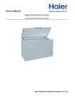
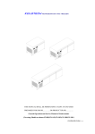
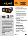
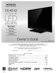
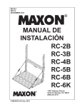
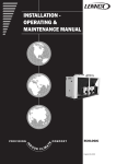
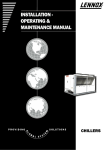
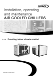
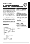
Service manual
for Haier Cold/Freezer rooms only
Sincere Forever
Haier Group
Haier Medical and Laboratory Products Co., Ltd
web:www.haiermedical.com
Add: No.1 Haier Road, 266101 Qingdao, P.R.China
1 Please read this manual carefully before use.
○
2 Please keep this manual properly for future reference.
○
1
Hair Bio-Medical
Haier Cold/Freezer Room Technical Handbook
With Monoblock Unit
Table of Contents
Part I Haier Monoblock Unit ……………………….…………3
Part II Installation…………………………………….………4-6
Part III Servicing manual…………………………...………7-10
Part IV Technical Drawings………………………………11-14
Haier Medical and Laboratory Products Co., Ltd
2
Hair Bio-Medical
Part I
Haier monoblock unit introduction
The Haier monoblock units are composed of a condenser unit, an
evaporator and a control panel, together in a single compact pack. This
configuration allows the highest simplicity on the hand of installation,
turning monoblock the most versatile, handy solution for all kind of cold /
freezer room projects. The monoblock refrigeration unit can meet the
freezing demand in the hotel, restaurant, hospital, agriculture, biology and
chemical industry, the temperature of which can be kept with in0 - 8℃,
-15- -25℃:
Monoblock units are equipped with:
Famous compressor brand: Maneurop, Danfoss, Copeland or Tecumseh.
Reliable performance and long life-span with well known brand
refrigeration parts. EBM fan motor, Castel Solenoid valve.
Danfoss high/ low pressure controller, Danfoss filter direr, Eliwell
thermostat.
Self-supporting housing of galvanized plate
Easily detachable front panels
Hermetic compressors with engine thermal insulation
Electronic control panel with 52 programmable parameters
Condensation by air.
3
Hair Bio-Medical
Part II
INSTALLATION
NOTE: Installation and maintenance are to be performed only by
qualified personnel who are familiar with local codes and regulations,
and experienced with this type of equipment. CAUTION: Sharp
edges and coil surfaces are a potential injury hazard. Avoid contact
with them.
Installation schematic drawing:
the roof
the wall
the hole
Push into
the hole
the door
the floor
Water pack storage
Installation schematic drawing
1.Monoblock Cooling/freezing Units, Panels, Doors, Service tools, Ice
4
Hair Bio-Medical
pack and Shelves are packed separately in wooden cartons.
wooden cartons
corner panel
2.Installation normally starts with the back wall panels or corner panel.
locks
3.Wall panels and floor lock together with cam locks. Haier cold/freezer
rooms are erected from inside, so installation in confined areas is simple.
Monoblock Units
roof
4.Monoblock Cooling/freezing Units are lifted into position and locked to
wall panels by pop rivets or self-tapping screws.
Note: Remove power cable from casing to ensure it is on the outside
5
Hair Bio-Medical
before setting roof.
5.Roof Panels installed last.
6.Affix Door handle and emergency release,
793 silicon joints between panels. Clean
panels with cleaner and cloth provided.
7.Connect
monoblock unit wire.
Plug into duty
sharing power source
and allow to pull
down to temperature
in line with normal
good refrigeration
practice.
monoblock unit connecting wire
8.Put up the shelves to either two or
three walls.
9.Place the Ice pack on the shelves with
holes.
6
Hair Bio-Medical
Part III
Servicing Manual
Troubles
Possible Cause
Compressor fails
to start(no hum)
1. Power failure
2. Disconnect switch open
3. Burned-out compressor motor
4. Control circuit open
a. Overload protector tripped
b. Thermostat setting too high
c. Low-pressure control open
d. High-pressure control open
e. Loose wiring
Compressor will
not start (hums
and trips
overload
protector)
1. Improperly wired
2. Low voltage to unit
3. Burned-out compressor motor
4. Mechanical problems in
compressor
5. Liquid refrigerant in compressor
crankcase
Compressor
starts and runs,
but short cycles
Corrective Action
1. Contact power company
2. Close switch and check circuits
3. Replace
4. Locate cause and repair
a. Check overload
b. Set to lower temperature
c. Reset and check pressures
d. Reset and check pressures
5. Repair wiring
1.Rewire unit
2.Determine reason and correct
3.Replace compressor motor
4. Replace compressor
5.Install crankcase heater
1. Defective overload protector
2. Low voltage to unit
3. Defective run capacitor
4. High discharge pressure
5. Suction pressure too low
6. Suction pressure too high
7. Compressor too hot
8. Shorted motor winding
9. Dirty or iced evaporator
10. Low-pressure control differential
set too close
11. High pressure control differential
set too close
12. Erratic thermostat
1. Replace overload protector
2. Determine reason and correct
3. Determine reason and replace
4. Open compressor discharge
service valve. Purge possible
overcharge of refrigerant. Provide sufficient
condenser cooling air to unit
6. Properly charge system with
refrigerant. Increase load on evaporator.
7. Reduce air flow over evaporator.
Purge overcharge of refrigerant.
Replace compressor valves
8. Properly charge system with
refrigerant.
9. Replace compressor
10. Increase air flow over evaporator.
Replace broken belt. Replace
defective fan motor.
11. Readjust differential.
12. Readjust or replace control
13. Relocate or replace thermostat
1. Short of refrigerant
1. Repair leak and recharge unit
7
Hair Bio-Medical
Unit operates
excessively
2. Thermostat contacts stuck
closed
3. Excessive load
4. Evaporator coil iced
5. Restriction in refrigerant system
6. Dirty condenser
7. Restricted air over evaporator
8. Inefficient compressor
2. Clean contacts or replace thermostat.
3. Check heaters, load and replace unit
accordingly; replace
insulation
4. Defrost unit and check operation
5. Locate and remove
6. Clean condenser
7. Determine cause and correct
8. Check compressor valves and
repair
Compressor
loses oil
1. Traps in hot gas and/or suction
lines
2. Refrigerant velocity too low in
risers
3. Shortage of refrigerant
4. Liquid refrigerant flooding back to
compressor
5. Gas-oil ratio low
6. Plugged expansion valve or
strainer
7. Compressor short cycling
8. Superheat too high at
compressor suction
1. Reroute lines to provide proper pitch
2. Resize risers or install oil return traps
3. Repair leak and recharge
4. Adjust expansion valve; alter
refrigerant charge on capillary
tube system
5. Add 1 pt of oil for each 10 1b of refrigerant
added to the factory charge
6. Clean or replace
7. See items under entry “Compressor starts
and runs, but
short cycles”
8. Change location of TXV bulb or adjust
superheat to return wet
refrigerant to the compressor
Compressor
noisy
1. Lack of compressor oil
2. Tubing rattle
3. Mounting loose
4. Oil slugging
5. Refrigerant flooding compressor
6. Dry or scored shaft seal
7. Internal parts of compressor
broken or worn
8. Compressor drive coupling
loose
1. Add oil to correct level
2. Reroute tubing
3. Repair mounting
4. Adjust oil level or refrigerant
charge
5. Check expansion valve for leak or oversized
orifice
6. Check oil level
7. Overhaul compressor
8. Tighten coupling and check
alignment
Unit low on
capacity
1. Ice or dirt on evaporator
2. Expansion valve stuck or dirty
3. Improper TXV superheat
adjustment
4. Wrong size expansion valve
5. Excessive pressure drop in
evaporator
6. Clogged strainer
1. Clean coil or defrost
2. Clean or replace expansion valve
3. Adjust expansion valve
4. Replace valve
5. Adjust expansion valve
6. Clean or replace strainer.
7.Subcool liquid or add refrigerant
8
Hair Bio-Medical
7. Liquid flashing in liquid line
Space
temperature To
high
1. Control setting too high
2. Expansion valve too small
3. Evaporator too small
4. Insufficient air circulation
5. Shortage of refrigerant
6. Expansion valve plugged
7. Inefficient compressor
8. Restricted or undersized
refrigerant Lines
9. Evaporator iced or dirty
1. Adjust control
2. Replace valve
3. Replace coil
4. Correct circulation
5. Repair leak and recharge
6. Clean or replace
7. Check efficiency
8. Clear restriction or resize lines
9. Clean and defrost evaporator
Suction line
frosted or
sweating
1. Superheat setting too low
2. Expansion valve stuck open
3. Evaporator fan not running
4. Overcharge of refrigerant
1. Adjust superheat setting
2. Clean or replace valve
3. Correct problem
4. Correct charge
Liquid line
frosted or
sweating
1. Restricted drier or strainer
2. Liquid line shut-off valve
Partially closed
1. Replace drier or strainer
2. Open valve
Hot liquid line
1. Expansion valve open too wide
2. Refrigerant shortage
1. Adjust expansion valve
2. Repair leak and recharge
Top of condenser
Coils cool when
unit is operating
1. Refrigerant shortage
2. Refrigerant overcharge
3. Inefficient compressor
1. Repair leak and recharge
2. Remove part of charge
3. Check efficiency and correct
Unit in
vacuum-frost on
expansion valve
only
1. Ice plugging expansion valve
orifice
2. Expansion valve strainer
plugged
1. Apply hot wet cloth to expansion valve
body; an increase in suction pressure indicates
moisture; install
a new drier
2. Clean strainer or replace valve
High head
pressure
1. Overcharge of refrigerant
2. Air in system
3. Dirty condenser
4. Unit in too hot location
5. Water-cooled condenser
plugged
1. Purge overcharge
2. Purge air
3. Clean condenser
4. Relocate unit
5. Clean or replace condense
Low head
pressure
1. Shortage of refrigerant
2. Cold unit location
3. Inefficient compressor valves
4. Leaky oil return valve in oil
separator
1. Repair leak and recharge
2. Provide warm condenser air
3. Replace leaky valves
4. Repair or replace
High suction
pressure
1. Evaporator overloaded
2. Expansion valve stuck open
3. Expansion valve too large
4. Leaking compressor suction valves
5. Evaporator too large
1. See previous entry ″Unit operates
excessively”
2. Repair or replace valve
3. Replace valve
4. Replace suction valves or compressor
9
Hair Bio-Medical
5. Resize evaporator
Low suction
pressure
1. Shortage of refrigerant
2. Evaporator underloaded
3. Liquid line strainer clogged
4. Plugged expansion valve
5. Last charge on TXV power
assembly
6. Space temperature too low
7. Expansion valve too small
8. Excessive pressure drop
through Evaporator
9. Oversized compressor
1.Repair leak and recharge
2.Clean or defrost evaporator
3. Clean or replace strainer
4. Clean or replace valve
5. Replace power assembly
6. Adjust or replace thermostat
7. Replace valve
8. Check for plugged external equalizer
9. Resize compressor
Evaporator coil
iced over
1. Automatic defrost control
erratic or inoperative
2. Automatic defrost control
improperly wired
3. Defective defrost control thermal
element
4. Improperly installed control
thermal element
5. Defrost control termination point
too low
1. Replace control
2. Rewire control
3. Replace control
4. Relocate element
5. Replace or adjust control
Cold room
remains in
defrost cycle
1. Defrost control incorrectly
wired
2. Automatic defrost control
inoperative
3. Defrost control termination point
too high
4. Defrost solenoid valve stuck open
5. Room temperature too low(below
55°F or 12.8°C)
1. Rewire defrost control
2. Replace defrost control
3. Replace or adjust control
4. Clean or replace solenoid valve
5. Relocate unit or provide heat
Water collects in
bottom of EMC
cooler
1. Drain tube plugged
2. Drain tube frozen
3. Split drain trough
4. Evaporator baffle not properly
installed
5. Humidiplate not adjusted properly
6. Door gasket not sealing
properly
1. Clean tube
2. Check drain heater element and repair or
replace
3. Replace trough
4. Install baffle properly
5. Adjust humidiplate
6. Adjust door or replace gasket
10
Hair Bio-Medical
Part IV
Technical Drawings
power wire
the lamp
monoblock unit
the door
installation schematic drawing
The monoblock unit structure:
monoblock unit structure
11
Hair Bio-Medical
Cooling principle chart:
Cooling principle chart
running
defrost
overload
alarm
lighting
power
Temperature controller
Controlling panel
12
Hair Bio-Medical
Electrical circuit diagram
L — Voltage connection
K2 — Lighting
N — Neutral connection
K1 —Control connection
M1 —Compressor
JC — Contactor
M2 — Condenser motor
QJZ — Crankcase heater
M3 — Evaporator motor
ZJC — Relay
RJ — Themo relay
DC —ELECTROMAGNETISM
XR40C—E— Tempreture thermostat
13
Hair Bio-Medical
Electrical principle chart
JC1--Comp.contactor
K--Start switch
W--Temp.control.power supply
WK1--Comp.
WK2--Evap.fans
WK3--Defrost
HP--High ang low pressure switch
RJ--Overload relay
ZJ--Intermediate relay
ZJ1--Evap.fans intermediate relay
ZJ2--Condensing fans
intermediate relay
DC1--Defrosting solenoid valve
DC2--Refrigerating solenoid
valve
M1--Compressor(Comp.)
M2--Condensing fans
M3--Evaporating fans
D1--Run light
D2--Defrosting light
D3--Overload light
14
Hair Bio-Medical