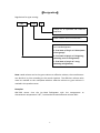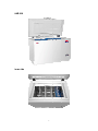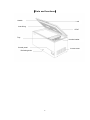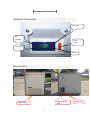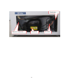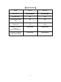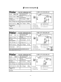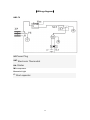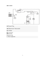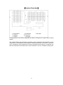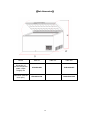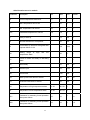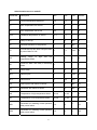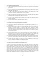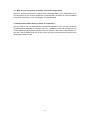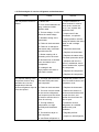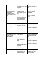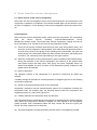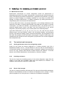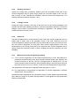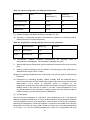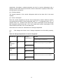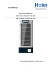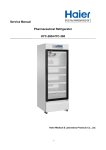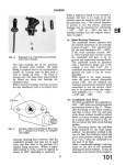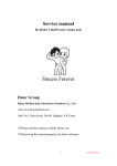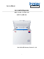
1
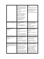
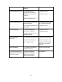
Se ervice Manual FILEE No.HMRSM M‐002‐02 Ice e Lined d Refriigerato or HB BC-70•HBC-110•HBC-200 116•HBD D-286 HBD-1 Haier Medical & & Laborato ory Produ ucts Co., Lttd. 1 Effective models This service manual is effective for following models Model name Product code climate type Voltage(V)/ Frequency(Hz) Plug‐type HBC‐70 ST 220V/50Hz British round plug HBC‐110 ST 220V/50Hz European plug HBC‐200 ST 220V/50Hz British round plug 2 Content 【Designation】 ....................................................................................................... 4 【Safe Caution】 ...................................................................................................... 5 【Product appearance】 .......................................................................................... 6 【Parts and functions】 ........................................................................................... 8 【component structure】 ........................................................................................ 9 【Specification】 .................................................................................................... 11 【Product nameplate】 ......................................................................................... 12 【Wiring diagram】 ................................................................................................ 13 【System flowchart】 ............................................................................................ 15 【Net dimension】 ................................................................................................. 16 【Installation and accessories】 ............................................................................ 17 【Adjustment of thermostat】 .............................................................................. 19 I. Introduction of display panel and buttons ..................................................... 19 II.Parameters and operation of controller ........................................................ 20 III.Menu description .......................................................................................... 22 【Function procedure】 ......................................................................................... 31 【System troubleshooting】 .................................................................................. 33 1.System troubleshooting ................................................................................. 33 2.Common failures in vaccine refrigerator ........................................................ 42 3.Maintenance refrigerator and technical requirements ................................. 44 4.Application and maintenance of vaccine refrigerator ................................... 46 5.Evacuating and filling procedures and tools needed ..................................... 49 6.Noise from the vaccine refrigerator ............................................................... 51 7.National noise standards ............................................................................. 56 8.Technology for measuring performance parameter ...................................... 58 【Details of wearing parts】 .................................................................................. 62 3 【Designation】 Regulations for type naming: HBC XXX X Design No. is expressed with character sequence Rated volume value is shown with L Ice Lined Refrigerator a: first letter of Pinyin of “Haier(name of the group)” b: first letter of pinyin of “bingxiang (meaning vaccine refrigerator)” c: first letter of pinyin of “cang (meaning refrigeration) Note: rated volume can be the gross volume or effective volume; the manufacturer can decide it by him according to the actual situation. The effective volume value must be marked on the nameplate whether effective volume or gross volume is marked in the product name. Examples: HBC‐200 means that the Ice-Lined Refrigerator with the temperature at characteristic temperature 2‐8℃, horizontal and rated effective volume 200 L. 4 【Safe Caution】 Please read carefully all these notes before application of the vaccine refrigerator. During application of the vaccine refrigerator, remember to comply with the following basic safety notes: 1. The vaccine refrigerator can only be used for purposes mentioned in this Instruction and Maintenance Guide. 2. The vaccine refrigerator shall be installed correctly according to instruction in the chapter of “installation”. For description before application, refer to earthing instruction in the chapter of “installation”. 3. Don’t remove plug of the vaccine refrigerator by pulling the power line, but clutch the plug and remove it from the electric socket. 4. Immediately repair or replace all worn or damaged power lines. Don’t use any power line with crack or scratch in the line, plug or connector end. 5. Remember to remove the plug of the vaccine refrigerator before cleaning or any repair. Caution: in case of demand on repair of the vaccine refrigerator, it shall be repaired by professional technical personnel. 6. If the old vaccine refrigerator is no longer in application, it is recommended from us that the vaccine basket be placed in a suitable place to reduce possibility of hazard to child. 7. The vaccine refrigerator is forbidden to be placed or embedded into a closed cupboard. It can only be independently installed. 8. The vaccine refrigerator is not allowed to put into application in places with explosive fume. 9. Don’t use the vaccine refrigerator for cooling foods. 5 【Produ uct appea arance】 HBC C‐70 HBC C‐110 6 HBC C‐200 Inn ner side 7 【Parts and functions】 Handle Lock Inner lining Cover Tray Vaccine basket Control panel Access cover Defrosting drain 8 【component structure】 Electronic Thermostat Increase FN: Function k Power switch Control keys Reduce Box structure Rodent control grille Cabin Grille 9 Power Cord Condenser Electronic Thermostat compressor Fan motor 10 【Specification】 Model HBC-70 HBC-200 Power (V/Hz) 220~240V/50Hz 220~240V/50Hz Net weight (Kg) 68 112 Total packaging weight (Kg) 69 114 Capacity (L) 70 200 Dimension of vaccine refrigerator (Width×Depth×Heihgt) 670×630×847 1240×630×847 Dimension of package (Width×Depth×Height) 755×760×900 1325×760×900 11 【Product nameplate】 12 【Wiring diagram】 HBC-70 XP-Power SATKA- Plug Electronic Thermostat Starter M1-compressor HYE-switch light C Start capacitor 13 HBC-110\200 XP-Power SATKA- Plug Electronic Thermostat Starter M1-compressor M2-fan motor HYE-switch light C Start capacitor 14 【System flowchart】 1-Compressor 4-Capillary 2-Condenser 5-Evaporator 3-Dry filter Cooling system of the vaccine refrigerator by Haier is composed of a type of direct cooling system. The cooling effects are achieved by operation of the compressor while operation of the compressor is controlled by the thermostat. Detailed information is as follows : operation of the compressor forces refrigerant (R134a) to gradually flow through the condenser, dry filter and evaporator and finally return to the compressor. This is a complete cooling cycle. 15 【Net dimension】 Model HBC-70 Dimension of vaccine refrigerator (width ×depth ×height) mm 670×630×820 1240×630×847 Dimension (with the door open) 670×630×1435 1240×630×1462 HBC-110 16 HBC-200 【Installation and accessories】 Removing package of ice lining vaccine refrigerator 1. Remove all packaging materials, including the foam base and all tape for fixing accessories inside and outside the vaccine refrigerator. 2. Before power is connected to the vaccine refrigerator, inspect and remove any remaining packaging material, tape or printed material. Adjusting vaccine refrigerator 1. The vaccine refrigerator is specially designed for independent installation, and it is not allowed to be placed or embedded into cupboard. 2. The floor for placement of the vaccine refrigerator shall be solid enough for bearing weight of the vaccine refrigerator stuffed with articles. 3. When removing the vaccine refrigerator, make sure the angle of inclination shall not be above 45 degrees. Otherwise, the compressor and the sealing system will be damaged. 4. If the vaccine refrigerator has been tilted, it shall be placed upright for at least 24h before it is plugged in. Good ventilation To ensure that the vaccine refrigerator reaches the designed maximum operating efficiency, it shall be installed in placed with good ventilation. Piping and electrical connection. Recommended space around the vaccine refrigerator is as follows: Side..............2″ (50mm) Top..............2″ (50mm) Back..............2″ (50mm) Installation and accessories Don’t overstuff the vaccine refrigerator to allow for good ventilation in it so that better refrigeration effects can be achieved. Electrical requirements Make sure there exists suitable power socket (220V) with correct earthing near the vaccine refrigerator. Avoid cutting the third earthing pin. Otherwise, it shall be very dangerous because 17 effective earthing will no longer be supplied to the vaccine refrigerator, which may cause electric shock. Installation restrictions Don’t install the vaccine refrigerator in any place with thermal insulation or improper heating conditions, such as garage, etc. The vaccine refrigerator shall be installed in suitable place with solid and smooth surface and it shall be kept from direct sunlight or heat sources (such as electric radiator, baseboard heater and cooker, etc). Installation and accessories After the vaccine refrigerator is installed in suitable place, plug into the 220V socket. The vaccine refrigerator is equipped with a thermostat for controlling temperature of the vaccine chamber. The temperature can be set between 2℃~8℃with the button “△” or “▽”. When the vaccine refrigerator is powered, the yellow light will on. After the vaccine refrigerator has been working for 48h and its temperature has been set as required, vaccine can be placed in the vaccine refrigerator. In case of removal of the plug of vaccine refrigerator or power failure, it can only be plugged in after 5min. (Caution: if the vaccine refrigerator has been placed flat or tilted for some time, it shall be kept upright for 24h before power is connected again for operation.) 18 【A Adjustment of th hermosta at】 I. Introoductionn of dispplay panel and buttons b Thre ee digits, a minus sign and 5 sym mbols (refrigeration, pow wer supply, lock, alarm and defrrosting) can be displayed on the dissplay panel. 1. on symbol. When W the co ompressor is s in operatio on, the symb bol is display yed. Refrigeratio 2. Power supp ply symbol. When exterrnal power supply s is con nnected to th he controllerr, the symbol is displayed. d 3. Lock symbol. When the e controller is locked, th he symbol iss displayed. 4. ol flashes to alert Alarm symbol. When the controller is in state of alarming, the symbo the user. W the co ontroller is in state off defrosting,, the symbol is 5. Defrosting symbol. When played. disp The ese four butttons conttroller. , , , and d Fn exist on o the instrrument for o operation off the 19 II.Parameters and operation of controller Under normal circumstances, the measured temperature is displayed by the controller, and in case of failure of the sensor, “Err” is displayed. When the sensor is above 85℃, “EHi” is displayed, while it is below -50℃, “ELo” is displayed. 1. Parameter setting method Setting control temperature Under normal circumstances, press the button temperature is displayed on the display screen; and release it, and the current control Increase or decrease the value with the buttons obtained; Confirm the new value by pressing the button returning to normal operating mode. or until the desired value is again, and save the new valuebefore Setting parameters of other general menus 1. Hold the button for more than 3s, and the parameter code “PS” (password) is displayed on the digital tube; 2. Roll parameters with the buttons 3. Confirm the parameter by pressing the button displayer; 4. Increase or decrease the value of the parameter with the buttons 5. Save temporarily the modified parameter value by pressing the button to the parameter displayed; 6. If values of other parameters are to modified, repeat steps 3~5; 7. Hold the button for more than 3s to save the modified parameter value and return to normal circumstances. and (PS, AB); , and value of the parameter is or ; , and return Setting parameters of administration menu: 1. Hold the button for more than 3s, and the parameter code “PS” (password) is displayed on the display screen; 2. Set the password by pressing the button 3. Roll the number to “-15” with the buttons 4. Confirm the password by pressing the button 5. Roll the parameter name with the buttons 6. Display the correspondent parameter value by pressing the button 7. Increase or decrease the value with the buttons 20 ; and ; ; and ; or ; ; 8. Save temporarily the modified parameter value by pressing the button to the parameter displayed; 9. If values of other parameters are to modified, repeat steps 5~8; , and return 10. Hold the button for more than 3s to save the modified parameter and quit the parameter setting program. Caution: if there is no button operation within 3min, the setting shall be automatically quitted and the controller is locked. Meanwhile, execution shall be implemented with the parameter memory last set. 21 III. Menu description Parameters of the controller are divided into general menu and administration menu. General menu Parameter Description Min. Max. Unit Default St Control temperature r1 r2 ℃ 5.0 PS Password to access administration menu -50 100 -- 0 Ab Select mode A b -- b St for controlling temperature With St >=2℃, when the temperature measured PV >= St + r0, the machine is started, and when PV <= St, it is stopped. With St <=2℃, when the temperature measured PV >= St + r0, the machine is started, and when PV <= St- r0, it is stopped. Setting range of St is determined by the parameters r1 and r2, with St <= r1 and St >= r2. PS, the password to access the administration menu When accessing the administration parameters, only with the correct password entered can the parameters of the administration menu be modified. If a wrong password is entered, the parameter setting will be quitted. Caution: the correct password is -15. Ab for selecting mode When mode A is selected, it is special for ice lining projects; mode b is a general mode, and mode A is default. When mode b is selected, the part of displayed temperature is specially treated to agree with the temperature display of the cabinet. When the measured temperature is between 2.5~7.5℃, the measured temperature is displayed with a refreshing frequency of 15s; If the measured temperature is above 10.0℃or below 1℃, the actual temperature is displayed; If the measured temperature is above 7.5℃ and below 10.0℃, 7.5 is displayed, and if it has been continuously above 7.5℃ for over 4min, the actual temperature is displayed. If the measured temperature is below 2.5℃ and above 1.0℃, 2.5 is displayed, and if it has been continuously below 2.5℃ for over 4min, the actual temperature is displayed. 22 Administration menu in mode A Parameter Description Min. Max. Unit Default r0 Control temperature difference 0.5 5.0 ℃ 1 r1 Max. temperature can be set r2 50 ℃ 8 r2 Min. temperature can be set -50 r1 ℃ 2 CAL Calibrated temperature of sensor -3.0 3.0 ℃ 0 t1 Delay in start-up 0 12 Min 0 t2 Shortest downtime of compressor 0 60 Min 0 t3 Forced start-up time after energized after a power failure of 15h 2 8.0 Hour 2 A0 Setting range of temperature alarm 1 20 ℃ 5 A1 Power-on alarm and delay in defrosting alarm 0 1 -- 0 A2 Alarm delay 0 30 Min 15 dF0 Defrost cycle 2 24 Hour 8 dF1 Defrost time 0 240 Min 0 ct0 Start-up time with failure of sensor 0 60 Min 15 ct1 Downtime with failure of sensor 1 60 Min 8 AH Temperature of high temperature alarm St- A0 St+ A0 ℃ 8 AL Temperature of low temperature alarm St- A0 St+ A0 ℃ 2 SP1 Parameter for restarting forced operation after power failure -10 10 ℃ 10 SP2 Parameter for restarting forced operation after power failure -10 10 ℃ 2.5 high and low 23 r0 for controlling temperature difference A parameter to control the start-up and stop of the compressor. Refer to description of the parameter St. r1 for setting maximum temperature To keep the setting range of control temperature St not above the parameter value of r1. Caution: minimum of r1 cannot be set to be below parameter r2, and it will vary with the variation of r2. r2 for setting the minimum temperature To keep the setting range of control temperature St not below the parameter value of r2. Caution: maximum of r2 cannot be set to be above the parameter r1, and it will vary with the variation of r1. CAL, calibrated temperature of the sensor Calibrate the error of the sensor The temperature displayed is equal to the actual value of the measured temperature plus the value of CAL. t1, delay in start-up When the compressor is started for the first time, it shall be started with a delay time of t1. t2, shortest downtime of the compressor After operation of the compressor is stopped, it can be started again after a delay of time t2. If t2 = 0, the delay is cancelled (not related to delay in start-up). t3, forced start-up time after energized after a power failure of 15h In case of a power failure over 15h, and when energized again, the compressor is required to be in continuous operation for a time of t3 before it has a downtown of 2h. t3=0 indicates no forced start-up when energized. A0, setting range of high and low temperature alarm Setting range of parameters AH and AL shall be between (St – A0) and (St + A0). 24 If St=5 and A0=6, then parameters AH and AL can only be adjusted between -1 and 11. A1, power-on alarm and delay in defrosting alarm The parameter is invalid in mode A. A2, alarm delay The parameter is invalid in mode A. dF0, defrost cycle When the compressor has a total running time of over dF0, defrosting is started. dF1, defrost time After defrosting is started and the defrosting time reaches dF1, the defrosting is stopped. If dF1=0, the defrosting function is invalid. ct0, start-up time with failure of sensor In case of failure of the sensor, run automatically a start-up time of ct0 and a downtime of ct1, and repeat the cycle. When ct0=0, the downtime continues. ct1, downtime with failure of the sensor Refer to ct0. AH, temperature of high temperature alarm When the measured temperature is above the set value of AH and after 10h, it still remains above AH, high temperature alarm occurs. Or when the measured temperature is above +10℃, the mode of high temperature alarm occurs: AL, temperature of low temperature alarm when the measured temperature is below the set value of AL and after 1h, it still remains below AL, low temperature alarm occurs. Or when the temperature is below -0.5℃, low temperature alarm occurs. SP1 SP2, parameters for restarting operation after the controller has power failure 25 After the controller has a power failure of 12h, and when it is started again, the program for controlling is forced to be run as follows: 1. Forced start-up for 3h first, 2. Running 2h with SP1 as the control temperature, 3. Running 2.5h with SP2 as the control temperature, 4. Forced shutdown for 0.5h at last. After completion in the above orders, return to the normal operating mode. In case of temperature below 1.0℃ during forced running of the program, return to the normal operating mode and forced running of the program ended in advance. The mode is only valid in mode A. 26 Administration menu in mode B Parameter Description Min. Max. Unit Default r0 Control temperature difference 0.5 5.0 ℃ 2 r1 Max. temperature can be set r2 50 ℃ 8 r2 Min. temperature can be set -50 r1 ℃ 2 CAL Calibrated temperature of sensor -3.0 3.0 ℃ 0 t1 Delay in start-up 0 12 Min 0 t2 Shortest downtime of compressor 0 60 Min 7 t3 Forced start-up time after energized after a power failure of 12h 0 8.0 Hour 0 A0 Setting range of temperature alarm 1 20 ℃ 6 A1 Power-on alarm and delay in defrosting alarm 0 1 -- 1 A2 Alarm delay 0 30 Min 1 dF0 Defrost cycle 2 24 Hour 8 dF1 Defrost time 0 240 Min 0 ct0 Start-up time with failure of sensor 0 60 Min 15 ct1 Downtime with failure of sensor 1 60 Min 8 AH Temperature of high temperature alarm St- A0 St+ A0 ℃ 8 AL Temperature of low temperature alarm St- A0 St+ A0 ℃ 2 SP1 Parameter for restarting forced operation after power failure -10 10 ℃ 10 SP2 Parameter for restarting forced operation after power failure -10 10 ℃ 2.5 high and low 27 r0 for controlling temperature difference A parameter to control the start-up and stop of the compressor. Refer to description of the parameter St. r1 for setting maximum temperature To keep the setting range of control temperature St not above the parameter value of r1. Caution: minimum of r1 cannot be set to be below parameter r2, and it will vary with the variation of r2 r2 for setting the minimum temperature To keep the setting range of control temperature St not below the parameter value of r2. Caution: maximum of r2 cannot be set to be above the parameter r1, and it will vary with the variation of r1. CAL, calibrated temperature of the sensor Calibrate the error of the sensor The temperature displayed is equal to the actual value of the measured temperature plus the value of CAL. t1 delay in start-up When the compressor is started for the first time, it shall be started with a delay time of t1. t2, shortest downtime of the compressor After operation of the compressor is stopped, it can be started again after a delay of time t2. If t2 = 0, the delay is cancelled (not related to delay in start-up). t3 forced start-up time after energized after a power failure of 6h In case of a power failure over 6h, and when energized again, the compressor is required to be in continuous operation for a time of t3. t3=0 indicates no forced start-up when energized. Caution: if the control temperature is above 0℃, when the measured temperature PV <=2℃, the machined is forced to be stopped. 28 A0, setting range of high and low temperature alarm Setting range of parameters AH and AL shall be between (St – A0) and (St + A0). If St=5 and A0=6, then parameters AH and AL can only be adjusted between -1 and 11. A1, power-on alarm and delay in defrosting alarm Valid only in mode B When energized for the first time and defrosting, the temperature of the cabinet will probably higher than that of the alarm setting value. When A1=1, no alarm occurs during energizing for the first time and defrosting and only after the temperature is below than the control temperature (St) will alarm be started. When A1=0. once the temperature is above AH or below AL, alarm occurs immediately. A2, alarm delay Only valid in mode B When the temperature is above AH or below AL, no immediate alarm occurs, but it occurs when the temperature has been continuously above AH or below AL for duration of A2. When A2=0, alarm delay is cancelled. dF0, defrost cycle When the compressor has a total running time of over dF0, defrosting is started. dF1, defrost time After defrosting is started and the defrosting time reaches dF1, the defrosting is stopped. If dF1=0, the defrosting function is invalid. ct0, start-up time with failure of sensor In case of failure of the sensor, run automatically a start-up time of ct0 and a downtime of ct1, and repeat the cycle. When ct0=0, the downtime continues. ct1, downtime with failure of the sensor Refer to ct0. 29 AH, temperature of high temperature alarm When the measured temperature is above the set value of AH, high temperature alarm occurs. AL, temperature of low temperature alarm When the measured temperature is below the set value of AL, low temperature alarm occurs. Parameters SP1 and SP2 are invalid in mode B. Inquiry to the maximum and minimum temperature: Hold the button flashing for 3s. for 3s, and the maximum temperature begins to be displayed by Hold the button flashing for 3s. for 3s, and the minimum temperature begins to be displayed by Clear maximum and minimum temperature records: Hold simultaneously buttons and for 3s, and the maximum and minimum temperature records are cleared, and “CLr” is displayed at the same time on the display screen for 2s. Lock and unlock the controller In case of no any button operation, the controller will be automatically locked within 3min while the buzzer will sound for about 0.5s. Hold simultaneously buttons and Fn for 1s, and the locked controller will be unlocked or the unlocked controller will be lock, while the buzzer will sound for about 0.5s. When the controller is locked, no operation can be performed on it and only after it is unlocked can operation on it be performed. 30 【 Function procedure】 Before vaccine is put into the vaccine refrigerator, the ice lining on four sides shall be frozen. To ensure freezing of ice lining on four sides, carry out the following operation: 1. Set the external thermostat to be 3℃. 2. Inspect the temperature indicated by the thermometer. (it must be between 2℃~5℃) Temperature inside the vaccine chamber must be continuously monitored with a thermometer and the temperature must be kept within the range of 2℃~8℃. The temperature shall be always be set between 2℃~5℃ due to tolerance of the thermostat. Be sure to use the ice box inside the vaccine box. In case of removal of the plug of the vaccine refrigerator or power failure, wait 5min before plugging in again. (Caution : if the vaccine refrigerator has been placed flat or tilted for some time, it shall be kept upright for 24h before plugging in again.) 31 【Brief description of thermostat principle】 When the internal temperature is above the set value, the compressor is in automatic operation controller by the thermostat. The temperature becomes lower and lower over time. When it reaches the set value, the compessor stops working. With the working cycle above, the internal temperature can be controlled to be around the set temperature. 32 【System troubleshooting】 1 System troubleshooting 1.1 Maintenance of vaccine refrigerator (1) Inspect the whole circuit of the vaccine refrigerator to make sure whether there is any falling off of wire connector, damage to the wire or shortcircuit. (2) Inspect the insulating layer of the vaccine refrigerator. Under normal circumstances, the resistance is over 2 megaohm; in case of a resistance less than 2 megaohm, further inspection of the resistance of the vaccine refrigerator is required. Set the voltmeter to R1 ohm shift, and plug the two pen voltage testers of the voltmeter into terminal L and N respectively to check the indicated value. The normal value shall be several ohm to tens of ohms. A zero ohm means shortcircuit of the vaccine refrigerator or shortcircuit brought by improper operation of the compressor/fan motor. Repair it after finding out the cause. A too large or infinite resistance means a broken circuit and please inspect it to have the problem settled. After implementation of the above inspection, the vaccine refrigerator will be free of electrical failure and you can have it connected to power for further inspection. 1.2 Cause of electric leakage of vaccine refrigerator (1) Electric leakage of the compressor : main due to violent vibration. Motor coil of the compressor contacts the shell, which causes falling off of coating of the plastic wires on some parts, thus contacting the shell. Other causes may include too high voltage, too low voltage, adverse cases for vaccine refrigerator (too high temperature, too poor ventilation and heat emission), and failure of the thermal protection device, etc. All these may cause overheating of the motor coil, loose insulating materials, or damage to insulating layer so that electric leakage occurs. (2) Electric leakage of wiring terminals of the motor : wiring terminals of hermetic compressor are made of ceramic fired at high temperature from soda glass, and high polymer is filled around the wiring terminal. Linear expansion coeffiecients of the terminal and the insulating material shall be the same and the insulating resistance between the terminal and the shell is required to be over 0.5million ohms. Cause for electric leakage on the terminal is damage to the soda glass or that there exists conductive materials (such as water and dirt, etc). In case of external electric leakage of the compressor, clean the compressor with CCL4 or alcohol. In case of internal electric leakage of the compressor, replace it. (3) Electric leakage of the thermostat : too long operation time, too high temperature, too much dirt or high humidity may cause electric leakage. If leakage occurs to the thermostat indeed, replace the thermostat. (4) Electric leakage of starter relay : during installation and maintenance, bolt of the relay conductor easily contacts the shell, thus causing electric leakage. If any improper relay operation is found, inspect it. In case of leakage, connect again and place a piece of insulating paper under the bolt. 33 (5) Electric leakage of the fan : too high ambient humidity or improper operation of the control device for the fan during the application of the vaccine refrigerator will burn the fan after it has been working for a long time, thus causing electric leakage. Measure the insulating resistance between each wiring terminal and cabinet of the vaccine refrigerator with the voltammeter. Too small resistance means a electric leakage caused by too high humidity ; a zero resistance means a burned or shortcircuited fan coil. Please replace the fan. 1.3 Troubleshooting by observation (1) Under normal circumstances, temperatures around surface of the evaporator of the vaccine refrigerator are almost the same and the frost layer has similar thickness. If there is no frost on surface of the evaporator (or the whole internal wall of a bed-type vaccine refrigerator) or on a small part on its top, the cooling system may have a fault including insufficient refrigerant or leakage. (2) Inspect the system piping to make sure there is no leakage, especially on the connector. Refrigerant with a small amount of refrigeration oil has good permeability. If case of occurence of leakage, oil stain will exist on the leakage spot. 1.4 Troubleshooting by sound (1) When the vaccine refrigerator is in normal operation, high-pressure liquid refrigerant flows into the low-pressure evaporator through the capillary, and sound of air flow and water flow can be heard. When opening the door of the vaccine refrigerator and getting close to the evaporator, the sound aboved mentioned can be heard. No sound or some occassional sound means leakage or insufficient filling of refrigerant in the system. (2) After power is connected, listen to the sound of the operation of the compressor to make sure whether the sound is normal. A low-pitched buzzing means abnormal starting of the motor. A rattling noise means damage of the suspended spring in the compressor or tilt operation of the compressor. In case of occurence of the above faults, replace the compressor. 1.5 Troubleshooting by touch (1) Touch the cover of the condenser, and after continuous operation, the temperature on top of the cover is the highest ; and the temperature of the bottom is almost the same as the indoor temperature. The temperature is related to the ambient temperature. In winter, the temperature is lower, so is the temperature of the condenser, and only a small part feels warm. In summer, the temperature is higher, so is the temperature of the condenser cover, and the whole condenser feels warm. (2) The high-pressure exhaust pipe has higher temperature, so in summer, when it is toughed with hand, it feels hot ; and so does it in winter. The low-pressure inlet pipe has lower temperature. In summer, dewdrops appear on the pipe wall, and when it is touched, it feels cool ; it feels even colder when touched in winter. 34 1.6 Troubleshooting by position 1) If the vaccine refrigerator is not level or the ground is soft, adjust the foot or make the ground solid. 2) In case of noise caused by loose bolt between the foot and the cabinet of the vaccine refrigerator, fasten the bolt. 3) In case of noise caused by aged rubber washer or loose fixing clamp of the compressor, replace the rubber washer or the fixing clamp. 4) If the pipe collide with the refrigerator cabinet or they collide with each other, related adjustment shall be implemented to get rid of the noise. 5) In case of noise caused by stuck fan blades, get rid of the barrier around the fan or adjust the fan blade. 6) In case of noise caused by loose fan support, fasten it. 1.7 Analysis of poor refrigerating effects and solution (1) Inspect the set value of the thermostat, and if it is not set within the range of 2℃~5℃, set it to be 3℃. (2) Inspect whether back and top of the vaccine refrigerator are too close to the wall ; whether it has direct sunlight or is close to heat sources ; whether the indoor temperature is too high ; whether the condenser is blocked by cloth, paper or dirt. Any of the above problems will have impact on heat emission of the condenser to reduce its refrigerating capacity. (3) Inspect whether whether too much vaccine is placed in the vaccine refrigerator. The placement of hot or too much vaccine is bad for the circulation of the cold air. Only after the hot vaccine is cooled can it be placed into the vaccine refrigerator. (4) Inspect whether the door of the vaccine refrigerator is closed, the door seal is too dirty or the door has bad sealing. Remove the dirt and add a small amount of talc powder. (5) Frequent open and closing of the door of the vaccine refrigerator and open of the door for a long time will reduce the refrigerating capacity. 1.8 How to settle the problem of bad sealing by seal In case of too many dirts or bad sealing, clean the seal with cloth dipped in warm water. After the cleaning, a small amount of talc powder shall be added. If there is still gap, blow the external surface of the seal with a hair dryer to heat it and keep the temperature between 50℃~60℃. Press the seal to recover it, and by pressing space around the seal with the hand, the seal can be recovered. If the method is invalid, stuff a piece of sponge around 10mm wide, 5mm thick and a bit longer than the gap into the seal, that is, teh position between the seal bottom and the door washer. The sponge will raise the gap position and it will adhere to the vaccine refrigerator body like at other positions. 35 1.9 Why vaccine refrigerator cannot be used at low temperature When the ambient temperature is below zero, lubricating ability of the refrigeration oil in the compressor of the vaccine refrigerator is reduced and it is difficult or even impossible to start the compressor, or the compressor may be damaged. 1.10 How to know about failure in motor of compressor It is very easy to find out motor failure by inspecting resistance of the coil. By connecting the ohmmeter to terminals of ”common” and “run”, resistance of the coil is measured. An infinite resistance value means a broken circuit of the coil. If the value of the resistance of the coil is much smaller than that of the motor, the motor must be short-circuited or the winding have been burned. 36 1.11 Fault analysis of vaccine refrigerator and maintenance Fault The compressor cannot be started Cause 1. Blown fuse 2. Poor contact between the plug, socket and cable. Broken cable. 3. Too low voltage, 10-15% below the rated voltage 4. Mistaken setting of the thermostat 5. Failure in the thermostat 6. Failure in or damage to the starter relay or thermal protection device 7. Broken starting coil or operating coil in the motor 8. Burned motor or blocked rotor and starter in the compressor 9. Leakage in the high-pressure air valve or the shaft is locked Solution 1. Inspect whether it is short-circuited: in case of short circuit, correct the error; if not, replace with applicable fuse. 2. Inspect and fix the connection, or replace it 3. Keep operation until the voltage is raised to the rated value or add a voltage stabilizer. 4. Reset the thermostat 5. Replace the thermostat 6. Replace the starter relay or thermal protection device 7. Measure with the R×1 shift of a multimeter, and in case of broken wire, replace the compressor. 8. Replace the compressor 9. Replace the compressor Too frequent starting of the compressor and too long operation time, but the temperature inside the vaccine refrigerator drops at a too slow speed 1. Too large space between the thermostat probe and the evaporator 1. Adjust the position of the probe to make it close to the evaporator cover. 2. Failure in the thermostat 2. Replace the thermostat 3. Too much vaccine stored in the vaccine refrigerator, too frequent open and close of the door and the door is open for too long 3. Reduce the amount of vaccine stored and the time to open the door, and shorten the time when the door is open. 4. Too high ambient temperature, too high humidity and blocked air flow 4. Install the vaccine refrigerator at a suitable position with good ventilation 5. Too thick frost layer on the evaporator 5. Regularly defrost 6. Insufficient refrigerant or 37 6. Inspect or add refrigerant leakage. 7. Replace the compressor 7. Reduced efficiency of the compressor 8. Replace with a new dry filter 8. The dry filter is blocked. The compressor keeps running and the temperature inside the vaccine refrigerator is too low. 1. Temperature of the thermostat is set to be too low. 2. The starter contact is stuck. 3. Improper position of the thermostat probe, thus causing maladjustment 1. Adjust to a suitable temperature 2. Repair or replace it 3. Adjust to a suitable position 4. Replace the compressor 4. Reduced efficiency of the compressor The compressor is buzzing and cannot be started with repeated tripping of the thermal protection device 1. Too low voltage 2. Failure in starter relay 3. Broken starting coil in the starting motor 4. The compressor is out of operation. After operation for a short time, the overload protection device is disconnected. 1. Too high voltage 2. Improper overload protection device and early tripping 3. The starter contact is stuck 4. Short circuit of the compressor 5. Mechanical failure in the compressor 1. Install a voltage stabilizer and adjust it to the rated value 2. Replace the starter relay 3. Replace the compressor 4. Axial piston in the compressor is blocked, and it shall be replaced 1. Install a voltage stabilizer and adjust it to the rated value 2. Replace the overload protection device 3. Replace the starter relay 4. Replace the compressor 5. Replace the compressor 6. Increase space for heat emission 6. Too high temperature around the compressor Too loud noise during operation of compressor 1. Soft ground 1. Reinforce the ground 2.Unstable and not flat cabinet of the vaccine 2. Stabilize body of the vaccine refrigerator 38 refrigerator 3. Resonance caused by the friction between piping and body of the vaccine refrigerator 4. Loose fixing screw of the compressor 3. Remove the pipe to avoid friction 4. Suitably fasten the screw 5. Adjust tightness of the shock absorber or replace the shock absorber 6. Replace the compressor 5. Too tight, too loose or aged shock absorber for fixing the compressor 6. Too loud noise in the compressor or broken suspended spring for reducing shock. No frost on the evaporator 1. Serious leakage of refrigerant. 2. The capillary or the system is blocked with dirt. Insufficient frost on evaporator 1. Little leakage of the refrigerant. 2. Blocked with dirt, but not serious 3. Reduced refrigeration capacity of the compressor Too rapid frosting, too thick frost layer or icing of the evaporator Electric leakage on body of the vaccine refrigerator, and a tingling when touched with hand 2. Clean the capillary or replace the filter 1. Inspect for leakage, repair welding and add refrigerant. 2. Clean the capillary and filter 3. Replace the compressor 1. Vaccine stored in the vaccine refrigerator is with water (not dry). 1. Dry the vaccine after it is cleaned before placing it into the refrigerator. 2. Too much vaccine stored in the vaccine refrigerator 2. Only vaccine with suitable amount is stored. 1. The body of the vaccine refrigerator has no earthing. 1. Earthing as specified 2. Binding post of the compressor contacts the shell of the cabinet, thus causing short circuit. 3. Damping of component of the electrical system, thus causing reduced insulating 39 1. Inspect for leakage, repair welding and add refrigerant. 2. Replace the compressor 3. Inspect carefully step by step. If the insulating capacity is seriously damaged, replace the component; remove the damp component and place it into a drying cabinet for Electric leakage of the fan capacity and electric leakage drying. 1. Too high ambient temperature or reduced insulating capacity of the insulator 1. Replace the fan 2. Replace the fan 2. Short-circuit between fan coil or burned fan coil Too loud noise in the fan Fan is not running 1. Fan blade is stuck or fan support is loose. 1. Clear barrier around the fan or fasten the support. 2. Too large space between fan shafts 2. Replace the fan 1. Inspect whether the connector is falling off. 1. Replace the fan 2. Replace the fan 2. Inspect whether the fan has been burned. Electric leakage of thermostat 1. Too longer operation time 1. Replace the thermostat 2. Too dirty environment 2. Clear dust with a brush 3. Too high humidity 3. Keep the thermostat dry and control the ambient humidity Thermostat failure 1. Leakage of temperature sensitive medium Replace the thermostat Poor contact between the temperature-sensing probe and the evaporator Improper installation position of the probe or change in the position during transportation Reinstallation 40 1.12 Fan replacement procedure (1) Disconnect the power and open the fan protection cover. (2) Unscrew the bolt of the fan with a straddle wrench or a universal tool. (3) Loosen the fan blades and take them out. (4) Take out the fan from between the compressor and the pipe. (5) Install a new fan from between the compressor and the pipe and install the fan blades in position before fixing them with a straddle wrench or a universal tool. (6) Trial operation; inspect whether the fan is in normal operation and whether the blades are blocked. (7) During the removal of the fan, remember not the bend or damage the pipe. 1.13 Thermostat replacement procedure (1) Disconnect the power. (2) Remove the protection cover on the side. (3) Loosen the clamp nut. (4) Hold the bottom of the temperature-sensing probe and pull it out downwards. (5) Replace with a new thermostat. 41 2 Common failures in vaccine refrigerator 2.1 The vaccine refrigerator cannot be started. With power on, the vaccine refrigerator cannot be started. First determine whether the failure is caused by internal or external factors. Including: (1) External factors ① Blown fuse, poor contact between the plug and the socket or too low voltage. (2) Internal factors ① Electrical failures in the vaccine refrigerator (usually caused by falling off of wire terminal or poor contact). ② Thermostat (with burned contact or damaged switching elements, etc). ③ Poor starting capacitor. ④ Poor starter relay or overload protector. Poor starter is usually caused by burned contact or falling off of weld; poor thermal protection device is usually caused by burned contact or poor heating wire. ⑤ Winding of the motor is burned. ⑥ The shaft of the compressor is damaged and block the cylinder. 2.2 Improper working of the vaccine refrigerator With power on, the vaccine refrigerator is started, but after several seconds or 1~2 minutes, it automatically stops before restarting after several minutes. It stops works within a short time after starting. Repetition goes on and it is impossible for normal operation. The following several causes may cause the problem: (1) Large voltage fluctuation A voltage of 220V is required for normal operation. If the voltage is too high, the current of the starter will correspondently increase. When the voltage exceeds the allowable value, the starting contact will keep connected for a long time and it cannot be released (under normal circumstances, the starting coil of the motor is disconnected within 1s after starting). This will rapidly increase the coil temperature, and then the thermal protection device is disconnected and it stops running. When power is off, the temperature of the thermal protection device rapidly falls, and when it reaches the reset temperature, power is connected. At this time, if the contact is not released, the starting contact may have close contact and mistaken connection, which may cause vibration of the compressor; the thermal protection device is disconnected after a short time. (2) Too high operating current intensity A vaccine refrigerator with too large operating current cannot be in normal operation. It may caused by the following two causes: First, the vaccine refrigerator automatically stops after several seconds after it is started, and then it is restarted again after several minutes before it stops again. If repetition goes 42 on, and after a long time, the motor or the starter and the thermal protection device will be burned. The main cause is the short circuit in some part of the starting coil. Second, after running for a certain period of time after the vaccine refrigerator is started, it automatically stops before the temperatures falls to the temperature needed. After a few minutes, the vaccine refrigerator is started again and power consumption is greatly increased. The cause is the poor insulation around the motor windings. 43 3 Maintenance refrigerator and technical requirements 3.1 Requirements on refrigeration equipment The compressor, condenser, evaporator and dry filter shall be the special type for R134a vaccine refrigerator, and they cannot be mixed up. 3.2 Requirements on repairing equipment (1) Evacuator and filler shall be special for R134a. (2) No special requirement on other equipment (such as pressure gauge), however, if they are applied in R134a vaccine refrigerator, they are not allowed to be applied for other purposes. 3.3 Maintenance procedures (1) Operation method for repairing equipment (refer to the operating instruction). (2) Special requirements ① Interval between turning on the compressor and beginning evacuating shall not exceed 10min. ② The evacuating duration shall not be less than 45min. ③ If leakage occurs on high-pressure end of the vaccine refrigerator, it can be repaired. Before welding, blow in N2 (nitrogen) with high purity. If leakage occurs on the low-pressure end, inspect the pressure of the system; if the system has no pressure, it shall be discarded, and a new vaccine refrigerator shall be bought; if there is pressure, it can be repaired. 3.4 Procedure for replacement of R134a compressor (1) Disconnect the power, and open the protection cover with a Phillips screwdriver or a universal screwdriver. (2) Remove electrical components of the compressor. (3) Unscrew the 4 assembling bolts of the compressor with a straddle wrench or a universal tool. (4) Take off the compressor. (5) Install a new compressor and filter dryer and fax them by welding. The system shall be open for duration not over 10min. (6) Connect the R134a recovery device to the pipeline on lower side of the compressor before evacuating. The evacuating duration shall not be less than 45min. (7) Pour R134a refrigerant into the system according to the former refrigerant charge. (8) Inspect whether there is leakage at the welded point with soapy water with foam. 44 (9) Wipe off welding powder and welding flux with clean gauze. (10) Connect the electrical control device of the compressor. (11) Install and adjust the thermostat. (12) Turn on the power for commissioning and check whether the unit is in normal operation. 12.3.5 Procedures for installation and brazing of compressor (1) Install a new compressor. (2) No direct inhalation of air into the compressor is allowed for inspection or other tests. (3) When replacing with a new compressor during maintenance, the sealing plug shall be opened at last and brazing and evacuating shall be implemented immediately. (4) When taking off the sealing plug of the compressor, and if there is no sound of air flow (no pressure), the compressor shall not be put into application. (5) If no sealing plug is installed in the compressor, the compressor shall not be put into application. (6) Hands of the maintenance operator shall be free of oil. (7) Only before application shall the filter dryer of the vaccine refrigerator be opened. 45 4 Application and maintenance of vaccine refrigerator 4.1 Product characteristics (1) The vaccine refrigerator uses refrigerant R134a completely free of CFC (chlorofluorocarbon), with an ozone depetion coefficient of [ODP (ozone depletion potential)] 0. Design with new climate type: the vaccine refrigerator has a design with wide temperature range. At temperature below 45℃(100℉), it can be freely started and stopped. (2) Design with a new refrigerating system: a two-way refrigerating system is applied to improve the refrigerating speed and extend the service life of the compressor. 4.2 Notice for use (1) The vaccine refrigerator must be kept level, and when it is moved, the angle of inclination shall not be over 45°so that the sliding door will not slide out of the guide and cause accidents. (2) The space between the vaccine refrigerator and other items shall be over 30cm to allow for ventilation and heat emission. (3) Don’t place the vaccine refrigerator at damp places or places with corrosive gases. (4) The vaccine refrigerator shall be placed at places with good ventilation, away from heat sources and without direct sunlight. (5) Before application for the first time, the vaccine refrigerator shall be in operation for a certain period of time (6h in summer and 4h in winter). When the temperature inside the vaccine refrigerator reaches 2℃or below, the vaccine can be placed into it. If the vaccine is placed into the vaccine refrigerator too early, it may be damaged, because the temperature inside the refrigerator is still higher. (6) Don’t overstuff the vaccine refrigerator. (7) Place reasonably the vaccine by category and try to control the frequency and time of opening door to reduce refrigerating loss and power consumption. (8) There are two feet at the bottom of the vaccine refrigerator to make adjustment on uneven floor. If frequent moving is required, place the vaccine refrigerator on a base with trolley. This type of vaccine refrigerator is usually used outdoors, so make sure the plug is fixed to avoid necessary loss caused by unfixed plug. (9) It is not allowed to store food, beverage or any other thing in the vaccine refrigerator. (10) When the vaccine refrigerator is used outdoors, don’t place it at places with direct sunlight. Regularly clean the inside and outside of the vaccine refrigerator, especially the part of the engine room, including the condenser and the compressor, etc. 4.3 Safety notice of the product (1) The vaccine refrigerator requires an independent earthing circuit with a minimum 46 current-carrying capacity of 5A. (2) If the cable is to be extended, the extended line shall have a area of not less than 1.5mm2 for the cross section. (3) Reliable earthing is required for the vaccine refrigerator; the earthing wire is not allowed to be connected to water pipe and gas pipe. (4) If power of the vaccine refrigerator is disconnected, wait at least 5min before the refrigerator is started again, otherwise, the compressor or the refrigerating system will be damaged. (5) Explosive materials, inflammables, volatile matters, glass container filled with liquid, alkali or corrosive acid are not allowed to be stored in the vaccine refrigerator. (6) Children are not allowed to play inside the refrigerator cabinet to avoid choke or damage. 4.4 Maintenance Defrosting: after being put into application for some time, a layer of frost appears in the inner tank. If the layer of frost is too thick, the refrigerating effects will be affected and the power consumption will be increased. (1) Regularly(when the frost layer is 5mm thick) get rid of the frost with a plastic shovel. (2) When defrosting, disconnect the power, take out the vaccine stored in the vaccine refrigerator and placed it in a place with low temperature. To accelerate defrosting, a container containing warm water can be placed inside the cabinet. (3) After the layer of frost melts, pull out the drain plug to empty the water, and then dry the vaccine refrigerator by wiping. (4) Cleaning: for sake of safety, disconnect the power before cleaning to avoid electric shock or damage to the vaccine refrigerator. (5) When cleaning the vaccine refrigerator, clean it with a piece of soft cloth or sponge dipped with clean water or soapy water (or non-corrosive neutral detergent). After cleaning, dry the vaccine refrigerator by wiping with cloth to avoid rust. (6) To ensure good refrigerating effects, please regulars clean the condenser, the compressor and dust-proof components inside the engine room with a soft brush. (clean the dust-proof components every 2~3 days) (7) Downtime: if the vaccine refrigerator is out of operation for a long time, disconnect the power, clean it with methods above mentioned, and open its door until it is dry before it is finally in safe-keeping. 4.5 Standard maintenance procedures (1) Clean cabinet of the vaccine refrigerator: remove the board on the cabinet and the protection cover on the back with a Phillips screwdriver. Clear dusts from the condenser, fan, compressor and thermostat with a brush. Clean it by wiping and avoid damage to the pipe and electrical parts. 47 (2) Connect the power, and inspect whether the vaccine refrigerator is in normal operation. In case of any abnormal case found, inspect it and repair it. (3) Inspect all brazed joints. In case of falling off of black paint or rust, polish the surface slightly with polishing paper 0#. When getting rid of rust, clean with a piece of clean towel. Then apply acid-soluble paint on the welded joint and pipes with a brush. (4) Inspect the foot; in case of any damage, replace it. (5) Inspect the power line; in case of any abrasive wear or damage, replace it. (6) Inspect whether the resistance of the earthing resistor is in normal operation with a multimeter. (7) Inspect the insulation with a multimeter; in case of any abnormal case found, inspect the circuit and each component. (8) In case of damage to the trademark or loss, replace with a new trademark of Haier. (9) Clean the inside and outside of the vaccine refrigerator. If the vaccine refrigerator is out of operation for a long time, dry off the water on it, put it into a plastic bag and place it in a dry storehouse with good ventilation. Remember to place it on flat floor. 48 5 Evacuating and filling procedures and tools needed 5.1 Tools and equipment for repairing vaccine refrigerator (1) Recycling machine (2) Nitrogen gas (N2) container, oxygen (O2) container, acetylene container and torch (3) Thermometer (4) Voltmeter (5) Pen voltage tester (6) Manifold pressure gauge (7) Flathead screwdriver (8) Phillips screwdriver (9) Needle nose pliers (sharp nose pliers), diagonal pliers and sealing pliers (10) Hansen valve (11) Pipe cutter 5.2 Notice for use R134a filling equipment is only special for R134a refrigerant. (1) It is not allowed to fill R134a refrigerant with R12 filling equipment. (2) Please keep the pliers, pipe cutting device and Hansen valve clean and make them free of oil stain. 5.3 Procedures for filling equipment (1) Preparation before application ① Visually inspect whether there is anything abnormal in the recycling machine, etc ② Keep all valves connected to the equipment closed until operation is really started. (2) Evacuate ① Connect hose of the recycling machine to the connector of the system ② Connect the power ③ Start the motor ④ Open all related valves ⑤ When the pointer of the vacuum gauge is gradually close to the graduation “-1”, observe the pointer. ⑥ Evacuating duration is required not to be less than 45min. 49 ⑦ Close all valves after the completion of evacuating. ⑧ Stop the motor (3) Filling ① First determine the filling volume according to the state of the vaccine refrigerator being repaired. (each small graduation on the liquid line means 25g, while each large graduation means 100g) ② Open all related valves ③ Close each valve when the level is raised to the filling volume (4) Commissioning ① After filling, connect the vaccine refrigerator to power for commissioning. Observe whether the vaccine refrigerator is in normal operation. ② Disconnect the power 50 6 Noise from the vaccine refrigerator 6.1 Noise sources of the vaccine refrigerator Noise from the vaccine refrigerator comes from thermal expansion and contraction of the compressor, evaporator or condenser; from contact between pipe or their resonance; from the flow of refrigerant; or from shaking of the vaccine refrigerator caused by uneven floor, etc. 6.2 Compressor Noise from the vaccine refrigerator mainly comes from the compressor. The compressor gives out various sounds, including continuous/discontinuous sound, periodic/non-periodic sound. The sounds have various frequencies, ranging from tens of Hz to thousands of Hz. Causes for the noise in the compressor include: (1) There are two pieces of flexible steel sheet (air inlet valve and exhaust valve), and when the vaccine refrigerator is being started, each steel sheet will open and close for 47 times every second, thus giving out the vibrating sound. Meanwhile, the open and closing action of the steel sheet makes the sheet contact other parts, which also gives out sound. The continuous buzz heard belong to this type of sound. (2) When the compressor is being manufactured, space inevitably exists between parts. During the operation of the vaccine refrigerator, the existence of the spaces make some parts contact with each other, thus giving out sound. Especially when it is started and stopped, the force on parts of the compressor greatly changes so that greater sound is produced. (3) Noise of liquid flow The operation process of the compressor is a process of continuous air intake and exhaust. If sudden changes in the intake or exhaust pressure of refrigerant gas occur, the vibrating sound will be produced. (4) Sound of resonance between parts of the compressor Sometimes, resonance may be caused between parts of the compressor including the compressor body, the exhaust pipe, the silencing device inside the compressor and supporting spring, etc, and sound is given out. (5) Collision between the compressor body and the shell The compressor body is suspended by three springs or supported by the spring inside the shell. When the compressor is started or stopped, the force applied on the compressor greatly changes, and it sometimes makes the body contact the shell, thus giving out sound. The case continues for a short time. (6) The electromagnetic sound produced by hermetic motor is comparatively smaller. 51 6.3 How the sound of water flow is produced? Answer: when the liquid refrigerant is flowing, especially flowing through the evaporator, it will produce a sound similar to that of water flow. The sound may vary because of the different technologies applied in the structure of the evaporator. If when the vaccine refrigerator is running, the sound is not produced with the evaporator not refrigerating and the condenser not hot, the refrigerant is restricted or there is leakage of the refrigerant. 6.4 Sound of air flow When the compressor is running, gas is continuously sucked in and discharged. When the liquid refrigerant flows through the capillary, gas injection occurs and the sound of air flow is produced. This kind of sound is normal, but it may vary in different vaccine refrigerators, for the compressor and the evaporator used are different. 6.5 Why clucks or clicking sounds are suddenly produced by the vaccine refrigerator? Answer: the sound is produced by the thermal expansion and contraction of the condenser and the evaporator, or it is produced by the ice on the surface of the evaporator shock heated or cooled suddenly. The sound may appear in the following cases: (1) For a new vaccine refrigerator, the internal stress of its materials exists. The material stress will disappear over time and less sound will be produced. (2) Uneven temperature in the vaccine refrigerator after defrosting. (3) When the door is opened for taking out the vaccine, the evaporator is heated suddenly. (4) In several minutes after the vaccine refrigerator is started or stopped, significant changes occur in the temperature of the condenser and the evaporator. Almost all things expand with heat and contract with cold, so the sound is normal. 6.6 Why the noise becomes greater after the vaccine refrigerator has been in service for some time? Answer: after being in service for half a year or a year, the space by abrasive wear between internal parts will be increased, and the noise from the compressor will also be correspondently increased. After that, during the whole service life of the vaccine refrigerator, the space between parts maintains stable. 6.7 Why the noise becomes greater after the vaccine refrigerator has out of service for some time? Answer: after the vaccine refrigerator has been out of service for a long time, the crankshaft of the compressor may be stuck by the dirt brought by the lubricant oil or by the lubricant oil frozen because of low temperature. Therefore, the compressor cannot be started or after it is started, it gives out greater noise and the abrasive wear of the 52 crankshaft is correspondently increased. It is recommended not to stop operation of the vaccine refrigerator. Sometimes, a new vaccine refrigerator also has such a characteristic. After being in service for some time, the vaccine refrigerator will become normal. 6.8 How to reduce noise from the vaccine refrigerator? Currently, all types of vaccine refrigerators have problem in noise. Scientists are always trying to find a solution to it, but little success has been achieved. The final solution depends on new technical improvement and development. 6.9 Why the noise from the vaccine refrigerator becomes greater at night? Answer: the impact of the noise from the vaccine refrigerator on people is related to the ambient noise level. In a crowded city or shop, noise from the vaccine refrigerator will be found to be little, while in a village or a quiet sitting room, the noise will be greater. That is why people find a vaccine refrigerator at home has greater noise than the one in the shop. 6.10 What regulations on noise from vaccine refrigerator have been made by the state? Answer: on side effects on people’s health by noise and the technical level which the current vaccine refrigerator industry can achieve, regulations on noise from vaccine refrigerators are provided by the national standard GB8059.1-87: vaccine refrigerator with a capacity of less than 250L shall have a noise level of not more than 52dB (A). The office or other public places we live in every day have much greater noise than vaccine refrigerators. 6.11 Why the noise level of vaccine refrigerator measured at home is not correct? Answer: environmental conditions for measuring noise from the vaccine refrigerator are not available at home, so the value measured is invalid. Conditions for noise measurement specified in national standards are as follows: (1) Measurement shall be carried out in semi-anechoic or anechoic rooms without reflection of sound wave. (2) Place the vaccine refrigerator on a elastic cushion 5~10mm thick. (3) Before measurement, have the vaccine refrigerator running idle for at least 30min. In case of suddenly stop, restart it and carry out the measurement after 3min. (4) 4 measurements shall be carried out, which are implemented respectively 1m from the front, the back, the left front and the right front of the vaccine refrigerator, with a measurement height of 1/2 of the height of the vaccine refrigerator; accurate sound level meter is applied (A weighted). 53 6.12 What are the differences between the national noise standard 52dB (A) and the standard 42dB by Ministry of Light Industry? The 52dB(A) in national standard is a sound power level. Under measurement conditions specified in national standards, the average of readings of the sound lever meter under circumstances with greater noise is taken among the noise from vaccine refrigerator measured at the 4 positions, so that the arithmetical mean of the noise at the 4 positions is measured. The value is the average sound pressure level of the noise, and the formula is as follows: LW = (LPA - 2) + 10 LgS Wherein, LW –sound power level in dB. LPA- average sound pressure level of the measured surface, in dB S–envelope area of the measured surface, in m2 The standard 42dB by the Ministry of Light Industry is a sound pressure level measured 1m from the door of the vaccine refrigerator. The value plus 10 shall be the approximate value of the sound power level. The restriction on noise in national standards is stricter and more scientific. Currently, it is required to applied the sound power level specified in national standards for noise from vaccine refrigerators. 6.13 Why noise varies from different types of vaccine refrigerators? Answer: the noise of each qualified vaccine refrigerator when leaving the factory is within the range specified in national standards. Different types of vaccine refrigerators have different power and different compressors are used in them, so the noise produced varies. Even in vaccine refrigerators of the same type, their compressor may produce different noise, and the noise may have different differences between the national standard 52dB(A), so the noise levels vary. 6.14 Why greater noise when the vaccine refrigerator is started and stopped? Answer: (1) When the vaccine refrigerator is being started, the starter relay gives out sound. Acceleration of the motor will cause vibration of the compressor and thus sound is produced. (2) When the vaccine refrigerator is stopped, the compressor will produce vibrating sound due to inertial rotation. (3) When the vaccine refrigerator is stopped, the compressor speeds down, and balance is achieved between the high pressure and low pressure at the exhaust pipe and return pipe, so sound is produced by the compressor. (4) When the compressor is started, great sound will be produced by the hammer-type starter relay in case of low voltage. Even with a voltage stabilizer installed, timely measurement of the voltage is still required. If requirement of stable voltage cannot 54 be achieved, there must be problem in quality of the voltage stabilizer. In case of low output voltage, don’t use the vaccine refrigerator. For causes above mentioned, sound is produced when the vaccine refrigerator is started and stopped. 6.15 Why sometimes the noise heard from a longer distance is greater than that heard from a shorter distance? Answer: transmission of noise from the vaccine refrigerator is related to factors including the position of the vaccine refrigerator and the indoor space size, etc. the sound wave produced by the operation of the vaccine refrigerator will reflect when bumping onto walls or furniture. Therefore, the noise heard from a place with longer distance may sometime greater than the one heard from a nearer place. For this reason, it is incorrect to come to a conclusion that the sound is great because it is heard several meters away. 6.16 How to determine that the sound is noise or it is normal? Answer: generally, noise from vaccine refrigerator within the range specified in national standards is normal. However, if a continuous sound of metal colliding with each other is produced by the compressor, inspect it in time to have it settled. 55 7 National noise standards There are related regulations in WHO. 7.1 No obvious noise when the vaccine refrigerator is running For vaccine refrigerators with a capacity of 250L or below, the sound power level measured by WHO shall not over 52dB(A). For vaccine refrigerators with a fan, the sound power levels of the noise shall be as follows: Below 300L ≤ 55dB(A) 300~400L (incl. 400L) ≤ 60dB(A) 401~500L (incl. 500L) ≤ 63dB(A) 7.2 Noise test In geometric center of the measurement site, place the empty vaccine refrigerator onto an elastic base (elastic rubber pad 5~6mm thick). Set the thermostat to 4, and close the door or cover. Carry out the measurement after the vaccine refrigerator has been in operation for 30min. During test, if the vaccine refrigerator reaches the temperature and stops, the measurement shall be interrupted, and it will not continue until 3min after the vaccine refrigerator is restarted. The test shall be implemented in semi-anechoic environment. Other test sites shall satisfy each regulation specified in WHO. Implementation of noise test is shown in figure 8. Place the sound transmission devices at measurement points 1, 2, 3 and 4 respectively, and measure the sound level with a sound level meter (A weighted). The larger reading shall be taken for calculation of the average value. The arithmetic mean at the above 4 measurement points shall be the average sound pressure level of the noise. Sound power level of vaccine refrigerator for the noise measurement can be calculated with the test results. LW = (LPA - 2) + 10LgS Herein, LW is for the sound power level in dB (with a reference value of 1PW); LPA is for the average sound pressure level of the surface measured, in dB (with a reference value of 20μPa); S is for the envelope area of the surface measured, in m2 Suppose l1, l2 and l3 are respectively the length, width and height of the vaccine refrigerator, and they are in meter. a=I1/2 + d b=I2/2 + d c=I3/2 + d If d=1m is taken, 56 Then, S= 4(ab+bc+ac) Positions of the measurement points are shown in table 4. 57 8 Technology for measuring performance parameter 8.1 Measurement content Measurement technologies for vaccine refrigerators include the measurement of refrigerating performance and safety requirements on electrical parts. Before leaving the factory, the following tests shall be implemented: (1) appearance requirements; (2) cooling speed; (3) electric leakage; (4) insulating resistance (in cold state); (5) electric field strength; (6) starting performance; (7) earthing resistance; (8) sealing performance of refrigerating system; (9) documents and attachments. Ex-factory field tests include: (10) storage temperature; (11) insulating resistance (in wet state and in hot state); (12) electric field strength (in wet state and in hot state); (13) power consumption; (14) noise and vibration; (15) galvanized parts; (16) painted cover; (17) protection against electric shock; (18) cable; (19) door opening force of the vaccine refrigerator; (20) freezing capacity; (21) increase speed of the load temperature. Type tests include items (1), (2), (8), (9), (10), (13), (17), (18), (20) and (21) and the following items: (22) total effective volume; (23) ice-making capacity; (24) defrosting property; (25) thermal insulating property and anti-condensation; (26) air tightness of the door seal; (27) durability of latch and handle; (28) strength of support or similar parts; (29) materials and odor inside the vaccine refrigerator; (30) firmness of the vaccine refrigerator and transportation test. 8.2 Test methods and instruments 8.2.1 Sealing performance test of the refrigerating system During the test, place the vaccine refrigerator in a positive pressure room with a temperature between 16~32℃. The leak detector is set to be with an annual leakage of 0.5g and each position in the refrigerating system is inspected. Leakage at any point shall not be over 0.5g. Common leak detectors include American GE products----H-25 leak detector and HLD4000 leak detector manufactured by a German company. 8.2.2 Insulating resistance The test is to inspect the insulating property of the vaccine refrigerator. Apply 500V DC voltage on live parts and accessible metal parts and measure the resistance. The resistance value shall not be less than 2 million ohm. 8.2.3 Electric field strength The test is to inspect the electric field strength of live parts and all accessible metal parts. Flashover and breakdown devices are used as test equipment, and a voltage of 1650V (50Hz) is applied for 2s. During the test, no flashover or breakdown shall appear. 58 8.4.2 Earthing resistance Inspect the voltage drop of between earthing point and accessible metal parts of the vaccine refrigerator with AC power supply which has a no-load voltage of not over 12V and a current of 10A. Calculate the resistance with the current and voltage drop. The earthing resistance shall not exceed 0.1 ohm. 8.2.5 Leakage current During test, apply a voltage 1.06 times of the rated one on the vaccine refrigerator and maintain the test under operating conditions. The test is specified in GB4706.1-84 and the leakage current meter is manufactured according to regulations. The leakage current measured shall not exceed 1.5mA. 8.2.6 Noise test The test is implemented in a semi-anechoic room. Place the vaccine refrigerator onto an elastic base 5~10mm thick in the geometric center of the room. During the test, the vaccine refrigerator shall be kept empty. Set the thermostat to be low and close the door. Run the vaccine refrigerator for more than 30min before implementation of the test. Requirements on the sound power level of the noise from the vaccine refrigerator are as follows: those with a capacity of 250L or below: ≤52dB(A); those with a capacity over 250L: ≤55dB(A). 8.2.7 Methods for testing refrigerating property (1) 4 or 6 vaccine refrigerators can be tested simultaneously in a lab. Polyurethane or polystyrene materials which have good thermal insulation property are applied in the enclosure structure of the lab. The lab is equipped with air retreating unit. Air with uniform pressure enter the lab from the perforated ceiling to ensure that the speed of the indoor air flow is not over 0.25m/s, so that the room temperature is kept uniform. The temperature in the lab can be adjusted within the range of 10~43℃. (2) For requirements on temperature for application of vaccine refrigerators in different climate areas, refer to table 6-1. Specified ambient temperature and a fluctuation range of ±0.5K shall be kept at each test spot. Within the range of 2m above the test platform, vertical gradient of the temperature shall not exceed 2K/m. 59 Table 6-1 Vaccine refrigerators for different climate areas Climate type Label Suitable temperature(℃) Measured temperature(℃) Mid temperate zone M 10~27 27 Temperate zone T 15~32 32 Tropical zone H 25~43 43 (3) Ambient humidity: the relative humidity is generally 15~19%. (4) Test pack: a rectangular test pack with dimensions shown in the following table is used as load for the vaccine refrigerator. Table 6-2 Test pack for testing property of the vaccine refrigerator Dimension(mm) Weight (g) Small (S) 100×100×50 200 Big (B) 100×100×100 400 Remarks (5) Thermometer: platinum resistance thermometers are generally measurement of temperature. They include the following two types: used for a. When measuring the temperature, place the platinum resistance directly into the test pack; b. Insert the platinum resistance into the middle of 4 tinned copper posts which have a diameter and a height of both 15.2mm. Bridges for measuring temperature with an precision of ±0.3K are used as measurement equipment. (6) Instruments for measuring humidity: relative humidity shall be measured with a wet-bulb thermometer and a dry-bulb thermometer. Place the dry-bulb and wet-bulb thermometers (1.5~2 layers of absorbent gauze is wrapped on the temperature-sensing parts of the thermometer and bottom of the gauze is placed into distilled water) in the wind with a speed of 2.5~3m/s. Record temperature on the dry-bulb thermometer and calculate the relative humidity with the “reference table of relative humidity for environmental tests” in GB6999-86. (7) Cooling speed Place the vaccine refrigerator in a lab with a room temperature of 32℃ and wait until balance (a temperature difference of ±1K) is achieved between the temperature inside the vaccine refrigerator and the room temperature. Close the door of the vaccine refrigerator, and keep the refrigerator in continuous operation. Record the time needed for the storage temperature tm to reach tm (max.) (With reference to table 13-3), the cooling temperature tm to reach +14℃ and the freezing temperature to reach its correspondent star level 60 respectively. According to related standards, the time for vaccine refrigerators with a capacity of below 250L shall not exceed 2h; while for those with a capacity of 250L~500L, the time shall not exceed 3h. (8) Freezing capacity The freezing capacity of the vaccine refrigerator shall not less than 90% of the rated capacity. (9) Power consumption Place the vaccine refrigerator in the lab. Room temperature for labs in different climates are respectively as follows: M (mid temperate zone): 27℃; T (temperate zone): 32℃; H (tropical zone): 43℃. Duration of the test is 24h. Power consumption of the cold storage and refrigerator shall be less than 115% of the rated value; power consumption of the freezer shall be less than 110% of the rated value. Other tests to be carried out: measurement of storage temperature (10) etc. Cold storage and freezer: test of storage temperature and ice-making capacity, Table 6-3 Storage temperature of vaccine refrigerator Climate type Climate type Ambient temperature(℃) Storage t1, t2, t3, t4, t5, t6, t7, t8, t9, t10 Mid temperate zone M Temperate zone T 10 2℃≤t1, t2, t3, t4, t5, t6, t7, t8, t9, t10≤8℃ 27 15 2℃≤t1, t2, t3, t4, t5, t6, t7, t8, t9, t10≤8℃ 32 Tropical zone H 25 2℃≤t1, t2, t3, t4, t5, t6, t7, t8, t9, t10≤8℃ 43 61 Details of wearing parts Model HBC‐70 SN 丹佛斯 NL6.1FT 0070701331 2 Thermostat 椿常电子温控器 0074091494 3 Power Cord 电源线 0070402374 4 Combination line 电连接组合线 0070402373 5 Cabin guard 机仓护罩 0071210004 6 Filter 干燥过滤器 0074180002A 1 Compressor 丹佛斯 NL6.1FT 0070701331 2 Thermostat 椿常电子温控器 0074091494 Fan motor 风机 EBM220V/60HZ/25W 0075030020 4 Combination line 5 Cabin guard 温控器连线 机舱护罩 6 Power Cord 电源线 0070402374 Filter 通用双抽过滤器 (20G 分子筛) 0074180002A 1 Compressor 丹佛斯 NL7FT 0070701332 2 Thermostat 椿常电子温控器 0074091494 Fan motor 风机 EBM220V/60HZ/25W 0075030020 3 4 Combination line 0070402373 0071210004 5 Cabin guard 温控器连线 机舱护罩 6 Power Cord 电源线 0070402374 Filter 通用双抽过滤器 (20G 分子筛) 0074180002A 7 62 code Compressor 7 HBC‐200 Chinese name 1 3 HBC‐110 SPARE PART 0070402373 0071210004 Inspired living Haier Medical & Laboratory Products Co., Ltd. Room 403D, Brand Building, Haier Industrial Park, No.1 Haier Road Qingdao China Website: www.haiermedical.com 63