1
Service Instructions
BYC-068-A
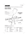
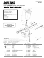
HVLP Transtec gravity feed spray gun
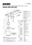
Model SGK - 600 - BV
Specifications:
• Pressure at spray gun inlet: up to 32 psi
• Paint flow rate: 190 ml/min
• Air consumption: 9,8 cfm
• Pattern size: 11" at 7" distance
Note: Figure obtained with metallic polyester base at
16 seconds viscosity #4 Ford cup.
Benefits:
• Less overspray
• Paint savings
• Cost reduction
Respect your work and protect
your equipment:
USE DEVILBISS ORIGINAL
SPARE PARTS.
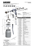
Replacement kits
K-5026:
Seal replacement kit, items 11(2x) and 12.
{ K-5027:
Air valve replacement kit, items 11(2x), 12, 13 and 14.
K-5028-14: Tip, needle and gasket replacement kit, items 3, 4, 6, 16 and 17.
Items 4, 11(2x), 12 and 32 replacement kit.
∇ K-5029:
K-5030:
Baffle replacement kit, items 4 and 5.
Ref.
1
2
3
∇ 4
5
6
7
8
9
10
{∇11
{∇12
{13
{14
15
16
Part N.°
SGK-0023
BSK-0158-510
SGK-0037
SGK-0036
SST-8416
SGK-0500
SGK-0501
SGK-0032
SGK-0034
-
Description
Retaining ring
Air cap
Fluid tip
Gasket
Baffle
Packing
Packing gland nut
Retaining ring
Spray pattern adjustment valve bushing
Spray pattern valve
U-cup seal
Air valve seat
Air valve stem
Air valve spring
Air valve bushing
Fluid needle
Ref.
17
18
19
20
21
22
23
24
25
26
27
28
29
30
31
∇ 32
Part N.°
SGK-0400
SGK-0035
PTGA-0029
BSS-240104
SGK-0041
SGK-0502
BSS-240106
K-5025
SGK-0020
SGK-0021
KGP-0012
KGP-0005
GFC-0402
GFC-0002
GFC-0501
-
Description
Fluid needle spring
Fluid adjustment knob
Nipple
Retaining ring
Air adjusting valve head
Air adjusting valve assembly
Retaining ring
Trigger pin assembly
Trigger
Fluid nipple
Gasket
Filter
Lid assembly
Drip free vent lid
Cup assembly
Assembly tool
Service Instructions
BYC-068-A
Description
Maintenance and Cleaning
The SGK-600BV spray gun has Transtec HVLP technology and is gravity fed.
It is a high production spray gun, ideal for spraying finishing materials, with
exception of corrosive and abrasive ones. It renders paint economy, less
overspray and ,consequently, reduces costs.
We recommend cleaning be done after using equipment:
1. Disconnect the spray gun from the air line.
2. Clean the cup and put clean solvent in same.
3. Open totally the fluid adjustment knob, press the trigger and let the solvent
flow through the fluid passage until it comes out completely clean.
4. Clean the gun body with a cloth wet with solvent, avoid waste of cotton
5. Remove the air cap and wash it in solvent using a brush or soft bristle
brush. Then dry it with an air jet.
6. If necessary, clean the air cap hole with a bristle or toothpick. NEVER
USE steel wire or hard instrument for this may damage the hole causing a
distorted spray pattern.
7. To avoid damaging the needle, make sure to pull the trigger and keep it
pulled while you are tightening or releasing the fluid tip, or remove the
fluid adjustment knob (18) to release the spring pressure.
8. Only remove the fluid tip when changing same or when there is internal
clogging.
9. For routine cleaning it is not necessary to remove the cup.
10. The recommended tightening of the tip is 150-180 lbf.inch.
Note: To replace both U-cup seal (11) and air valve seat (12) see the procedure
described in Service Instructions of the K-5029 kit.
Installation
Connect the spray gun to a clean air source, free of humidity and oil, by using
at least a 5/16” internal diameter hose. Depending on the length of the hose, a
bigger internal diameter may be necessary. Press the spray gun trigger and
adjust the inlet air pressure at the handle of the gun to approximately 25 psi.
Operation
Prepare the material to be sprayed according to the manufacturer’s
instructions. Filter the material through a 100 mesh screen.
Regulate the air pressure at the DeVilbiss filter regulator
Make a spray test.
Regulate the spray pattern by opening or closing the spray pattern valve
knob (10)
Spray a small area to adjust the work speed and desired finishing. If
finishing is too dry or rough, the amount of material is too small in relation
to the air pressure. Turn the fluid adjustment knob (18) counter clockwise,
or decrease the air pressure at the filter regulator.
Keep the spray gun always perpendicular to the surface being painted.
Do not move your hand in an arch. The arch movement produces a nonuniform paint layer.
We recommend the spray gun be kept at a distance of 6 to 8 inches from
the surface.
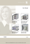
The position of the air cap determines the position of the pattern. Turn the
air cap according to requirements.
d.
a.
Service Check
Causes
Material buildup at air cap.
Partial obstruction of air cap horn holes or
central holes.
Material buildup at the fluid tip or partial
obstruction of same.
Damaged fluid tip.
Excess material.
b.
a.
b.
Very thick material.
Air pressure too high.
Lack of material.
b.
a.
b.
a.
b.
c.
a.
b.
c.
d.
e.
a.
Lack of material.
Obstructed fluid passage.
False entrance of air in paint line.
Low air pressure at spray gun.
Fluid regulating knob closed.
Material is too thick.
Air cap is loose.
Material buildup in between tip and air cap.
Fluid tip or needle worn or damaged.
a.
b.
c.
a.
b.
c.
d.
e.
a.
b.
Gasket holding the needle.
b.
Defect
Heavier spray on top or
below.
Defective configuration in
curve shape.
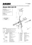
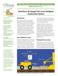
Lubrication
For best results, oil the indicated points daily
We recommend the use of the SSL-10 DeVilbiss oil.
a.
b.
c.
a.
b.
c.
d.
a.
Heavy spray in the center
Split spray.
Jerky or fluttering spray.
Will not spray.
Dripping or material leakage
through the tip.
A.
Trigger areas
B.
Needle gasket
C.
Adjustment valves
D.
Retaining ring
E.
Air valve
Correcting
Remove air cap and wash it with solvent.
Remove air cap and wash it with solvent (see
maintenance and cleaning).
Remove the tip and wash it with solvent.
Replace the tip and needle assembly.
Reduce the material flow by closing the fluid
adjustment knob.
Dilute the material.
Reduce air pressure at DeVilbiss filter regulator.
Increase material flow opening fluid.
Refill paint recipient.
Clean fluid passage.
Check paint line.
Check air line or increase pressure.
Open fluid adjustment knob (see Operation).
Dilute material.
Tighten air cap.
Clean tip externally and the central air cap hole.
Change the tip and needle assembly (see item 7 in
Maintenance and Cleaning).
Lubricate the gasket (item 6) when new, or change it,
lubricate and adjust.
With 14 psi at spray gun inlet air cap pressure is 10 psi.
DeVilbiss maintains the right to modify the characteristics of its products without previous notice.
Warranty
DeVilbiss equipment has a six month warranty from the date of purchase. This warranty will be limited to material, manufacturing and workmanship defects; bad use or repairs effected by non authorized people imply
in automatic loss of the warranty;
When repairs are necessary, take your equipment to a DeVilbiss Authorized Distributor where the repair will be effected by specialized technical people and only charged if equipment it outside warranty.