1
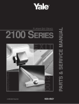
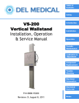
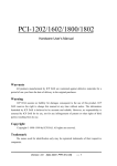
5300LN SERIES
5300LN
KEY-IN-LEVER
PARTS
PARTS & SERVICE MANUAL
GRADE 2 KEY-IN-LEVER CYLINDRICAL LOCKSET
HOW TO ORDER PARTS
To order parts, use the appropriate part number and specify finish if necessary.
For example, to order 10 lockbodies for ten Entrance
Function (5307LN), use the following configuration:
To order 10 sets of Augusta Levers for an Entrance Function
in Satin Chrome, use the following specification:
Quantity
Part Number
Description
Quantity
Part Number
Description
10
14-5307-0701-048
5307LN Lockbodies
10
14-5300-6039-025
Outside AU Cylinder Lever
in 626
To order 10 plug retainers for the 1802 Key-in-Lever Cylinder, use the following specification:
Quantity
Part Number
Description
10
99-9999-4561-999
1802 Cylinder Plug Retainers
-Please refer to the installation instructions for complete installation.
-For further assistance, contact your authorized YSG Door Security Consultants distributor or contact YSG directly at (800) 438-1951.
FINISH CHART
FINISHES
Finish
605*
606*
609
612
613
613e*
616
619
625
626
693
Description
Bright Brass, PVD
Satin Brass, PVD
Satin Brass, Blackened, Satin Relieved
Satin Bronze
Dark Oxidized Satin Bronze, Oil Rubbed
Dark Oxidized Satin Bronze, PVD
Satin Bronze, Blackened, Satin Relieved
Satin Nickel
Bright Chrome
Satin Chrome
Black Powder Coat
Roses
Levers
003
004
609
010
007
13e
616
619
026
025
200
043
044
609
050
060
13e
616
619
026
025
200
Pushbuttons/
Turnbuttons
043
044
609
050
060
13e
616
619
026
025
200
Cylinder
Plugs
004
004
004
004
004
004
004
025
025
025
025
*PVD finish standard on 605 and 606. Available as an option on 613 (as 613e) for customers desiring a non-wearing finish.
PVD LIFETIME FINISH
Physical Vapor Deposition (PVD) is a technologically advanced finish coating that provides the ultimate surface protection against
environmental elements and everyday wear and tear. PVD matches clear coated finishes in appearance, yet surpasses them in
durability. Yale warrants all its PVD finishes against corrosion, tarnish, wear, discoloring and peeling for the lifetime of the part to
which it has been applied. Ask your sales representative for specific warranty information.
FINISH CARE
5300LN Cylindrical Locks are designed to provide the highest standard of product quality and performance. Care should be taken
to ensure a long-lasting finish. When cleaning is required, use a soft damp cloth. Using lacquer thinners, caustic soaps, abrasive
cleaners or polishes could damage the coating and result in tarnishing.
FINISH CHART
MAINTENANCE
Yale 5300LN Cylindrical locks are manufactured to be maintenance free under normal operating conditions and environments.
Subjection to extremely heavy traffic and/or particularly dusty and dirty environmental conditions, however, may eventually cause
unsatisfactory operation due to slow moving parts or sticking cylinders. In this case, it may be necessary to clean and re-lubricate
the lockset to maintain optimum performance. To clean the lockset mechanism, use a penetrating or solvent type lubricant to
loosen sticking components, then lubricate with lithium grease. To free sticking or jammed cylinders, lubricate with graphite or a
non-oily lubricant (such as Lock-EZE). Do not use petroleum-based lubricants in the cylinder keyway.
Page 2
September 2003
5300LN Series Parts & Service Manual
TABLE OF CONTENTS
Lockbody Assemblies (by Function)
Function
5301LN
5302LN
5303LN
5305LN
5307LN
5308LN
5321LN
5322LN
5328LN
5329LN
ANSI
F75
F76
F77
F86
F81/F82
F84
F80
F90
-
Description . . . . . . . . . . . . . . . . . . . . . . . . . . . . . . . . . . . . . . . . . . . . . . . . . . . . . .
Page
Passage or Closet . . . . . . . . . . . . . . . . . . . . . . . . . . . . . . . . . . . . . . . . . . . . . . . . . . . . . . . . .4
Privacy, Bedroom or Bathroom . . . . . . . . . . . . . . . . . . . . . . . . . . . . . . . . . . . . . . . . . . . . . . . .5
Patio . . . . . . . . . . . . . . . . . . . . . . . . . . . . . . . . . . . . . . . . . . . . . . . . . . . . . . . . . . . . . . . . . . . .5
Storeroom or Closet . . . . . . . . . . . . . . . . . . . . . . . . . . . . . . . . . . . . . . . . . . . . . . . . . . . . . . . .6
Entrance or Office . . . . . . . . . . . . . . . . . . . . . . . . . . . . . . . . . . . . . . . . . . . . . . . . . . . . . . . . . .7
Classroom . . . . . . . . . . . . . . . . . . . . . . . . . . . . . . . . . . . . . . . . . . . . . . . . . . . . . . . . . . . . . . . .8
Communicating . . . . . . . . . . . . . . . . . . . . . . . . . . . . . . . . . . . . . . . . . . . . . . . . . . . . . . . . . . . .9
Dormitory . . . . . . . . . . . . . . . . . . . . . . . . . . . . . . . . . . . . . . . . . . . . . . . . . . . . . . . . . . . . . . .10
Passage Lever x Blank Plate . . . . . . . . . . . . . . . . . . . . . . . . . . . . . . . . . . . . . . . . . . . . . . . .11
Keyed Lever x Blank Plate . . . . . . . . . . . . . . . . . . . . . . . . . . . . . . . . . . . . . . . . . . . . . . . . . .12
Lever/Rose Assemblies
Outside Rose Assembly (Standard Cylinder)
Used on Functions 5303LN, 5305LN, 5307LN,
5308LN, 5321LN, 5322LN . . . . . . . . . . . . . . . . . . . . . . . . . . . . . . . . . . . . . . . . . . . . . . . . . . . . . . . . . . . . . . . . . . . . . . . . .13
Inside Rose Assembly . . . . . . . . . . . . . . . . . . . . . . . . . . . . . . . . . . . . . . . . . . . . . . . . . . . . . . . . . . . . . . . . . . . . . . . . . . . . . . .14
Lever & Rose Assembly (Removable Core)
Used on Functions 5305LN, 5307LN,
5308LN, 5322LN . . . . . . . . . . . . . . . . . . . . . . . . . . . . . . . . . . . . . . . . . . . . . . . . . . . . . . . . . . . . . . . . . . . . . . . . . . . . . . . . .15
Accessories
Lever Designs . . . . . . . . . . . . . . . . . . . . . . . . . . . . . . . . . . . . . . . . . . . . . . . . . . . . . . . . . . . . . . . . . . . . . . . . . . . . . . . . . . .16
Cylinders . . . . . . . . . . . . . . . . . . . . . . . . . . . . . . . . . . . . . . . . . . . . . . . . . . . . . . . . . . . . . . . . . . . . . . . . . . . . . . . . . . . .16-17
Strikes . . . . . . . . . . . . . . . . . . . . . . . . . . . . . . . . . . . . . . . . . . . . . . . . . . . . . . . . . . . . . . . . . . . . . . . . . . . . . . . . . . . . . . . . .18
Latchbolts . . . . . . . . . . . . . . . . . . . . . . . . . . . . . . . . . . . . . . . . . . . . . . . . . . . . . . . . . . . . . . . . . . . . . . . . . . . . . . . . . . . . . .19
Installation Instructions
Lockset Installation . . . . . . . . . . . . . . . . . . . . . . . . . . . . . . . . . . . . . . . . . . . . . . . . . . . . . . . . . . . . . . . . . . . . . . . . . . . .20-21
Cylinder and Lever Installation . . . . . . . . . . . . . . . . . . . . . . . . . . . . . . . . . . . . . . . . . . . . . . . . . . . . . . . . . . . . . . . . . . . . . .22
Removing Cylinder Handle . . . . . . . . . . . . . . . . . . . . . . . . . . . . . . . . . . . . . . . . . . . . . . . . . . . . . . . . . . . . . . . . . . . . . . . . .22
Adjusting for Door Thickness for 5328LN/5329LN
Functions Only . . . . . . . . . . . . . . . . . . . . . . . . . . . . . . . . . . . . . . . . . . . . . . . . . . . . . . . . . . . . . . . . . . . . . . . . . . . . . . . .23
Dummy Trim Installation . . . . . . . . . . . . . . . . . . . . . . . . . . . . . . . . . . . . . . . . . . . . . . . . . . . . . . . . . . . . . . . . . . . . . . . . . . .23
Strike Installation (Wood Frames Only) . . . . . . . . . . . . . . . . . . . . . . . . . . . . . . . . . . . . . . . . . . . . . . . . . . . . . . . . . . . . . . .23
Troubleshooting . . . . . . . . . . . . . . . . . . . . . . . . . . . . . . . . . . . . . . . . . . . . . . . . . . . . . . . . . . . . . . . . . . . . . . . . . . . . . . . . . .23
5300LN Series Parts & Service Manual
September 2003
Page 3
5301LN
Passage Lockset F75
1.2
Sold as complete lockbody
assembly only.
1.1
3
2
1.1
6.1
1.2
4
2
ITEM
5.1
QUANTITY
Assembly #
Assembly #
*14-5301-0701-048
*14-5301-0702-048
1-3/8" to 1-3/4"
2" to 2-1/4"
DOOR
DOOR
DESCRIPTION
1.1
Flange (Standard Door)
2
-
1.2
Flange (Thick Door)
-
2
2
Spindle - Inside
2
2
3
Frame
1
1
4
Spring - Retractor
2
2
5.1
Locator, Retractor Spring
1
1
6.1
Retractor #1
1
1
Page 4
September 2003
5300LN Series Parts & Service Manual
5302LN/5303LN
1.2
Sold as complete lockbody assembly only.
15
Privacy Lock F76
13
Patio Lock F77
14
17
16
12
3
1.1
9
2
10.1
6.2
8
1.1
1.2
4
11.1
5.2
QUANTITY
Assembly #
Assembly #
*14-5302-0702-048
*14-5302-0703-048
1-3/8" to 1-3/4"
2" to 2-1/4"
DOOR
DOOR
7
ITEM
DESCRIPTION
1.1
Flange (Standard Door)
1.2
2
-
Flange (Thick Door)
-
2
2
Spindle - Inside
1
1
3
Frame
1
1
4
Spring - Retractor
2
2
5.2
Catch
1
1
6.2
Retractor #2
1
1
7
Spindle, Outside
1
1
8
Seat, Spring
1
1
9
Spring, Pawl
1
1
10.1
Pawl
1
1
11.1
Tube, Release
1
1
12
Stem Assembly
1
1
13
Bank, Spring
1
1
14
Spring, Stem
1
1
15
Washer, Connecting
1
1
16
Speed Clip
1
1
17
Adjusting Tube
1
1
5300LN Series Parts & Service Manual
August 2003
Page 5
5305LN
1.1 or 1.2
Storeroom Lockset F86
2
Sold as complete lockbody
assembly only.
3
10.1
8
9
1.1
or
1.2
11.2
4
5.2
24
ITEM
7
6.2
QUANTITY
Assembly #
Assembly #
*14-5305-0080-048
*14-5305-0079-048
2" to 2-1/4"
1-3/8" to 1-3/4"
DOOR
DOOR
DESCRIPTION
1.1
Flange (Standard Door)
2
-
1.2
Flange (Thick Door)
-
2
2
Spindle - Inside
1
1
3
Frame
1
1
4
Spring - Retractor
2
2
5.2
Catch
1
1
6.2
Retractor #2
1
1
7
Spindle, Outside
1
1
8
Seat, Spring
1
1
9
Spring, Pawl
1
1
10.1
Pawl, Modified
1
1
11.2
Tube, Release
1
1
Page 6
September 2003
5300LN Series Parts & Service Manual
5307LN
16
1.1 or 1.2
Entrance Lock F81/82
Sold as complete lockbody
assembly only.
15
13
2
12
3
17
14
1.1
or
1.2
8
9
10.1
6.2
4
11.2
5.2
QUANTITY
Assembly #
Assembly #
*14-5307-0701-048
*14-5307-0702-048
1-3/8" to 1-3/4"
2" to 2-1/4"
DOOR
DOOR
7
ITEM
DESCRIPTION
1.1
Flange (Standard Door)
1.2
2
-
Flange (Thick Door)
-
2
2
Spindle - Inside
1
1
3
Frame
1
1
4
Spring - Retractor
2
2
5.2
Catch
1
1
6.2
Retractor #2
1
1
7
Spindle, Outside
1
1
8
Seat, Spring
1
1
9
Spring, Pawl
1
1
10.1
Pawl
1
1
11.2
Tube, Release
1
1
12
Stem Assembly
1
1
13
Bank, Spring
1
1
14
Spring, Stem
1
1
15
Washer, Connecting
1
1
16
Speed Clip
1
1
17
Adjusting Tube
1
1
5300LN Series Parts & Service Manual
September 2003
Page 7
5308LN
1.2
Classroom Lock F84
Sold as complete lockbody
assembly only.
1.1
2
3
21
10.1
9
19
20
8
1.1
4
1.2
18
5.1
6.1
7
QUANTITY
ITEM
Assembly #
*14-5308-0064-048
1-3/8" to 1-3/4"
DOOR
DESCRIPTION
Assembly #
*14-5308-0065-048
2" to 2-1/4"
DOOR
1.1
Flange (Standard Door)
2
-
1.2
Flange (For 2” to 2-1/4” Door)
-
2
2
Spindle - Inside
1
1
3
Frame
1
1
4
Spring - Retractor
2
2
5.1
Locator, Retractor Spring
1
1
6.1
Retractor #1
1
1
7
Spindle, Outside
1
1
8
Seat, Spring
1
1
9
Spring, Pawl
1
1
10.1
Pawl
1
1
18
Release Tube
1
1
19
Stop Pin
1
1
20
Cam Tube Driver
1
1
21
Cam Tube
1
1
Page 8
August 2003
5300LN Series Parts & Service Manual
5321LN
9
8
10.1
Sold as complete lockbody assembly only.
Communicating Lock F80
2
18
1.2
21
1.1
3
10.1
9
8
20
21
19
19
20
1.1
4
1.2
5.1
18
6.1
7
QUANTITY
ITEM
Assembly #
*14-5321-0001-048
1-3/8" to 1-3/4"
DOOR
DESCRIPTION
Assembly #
*14-5321-0002-048
2" to 2-1/4"
DOOR
1.1
Flange (Standard Door)
2
-
1.2
Flange (Thick Door)
-
2
2
Spindle - Inside
1
1
3
Frame
1
1
4
Spring - Retractor
2
2
5.1
Locator, Retractor Spring
1
1
6.1
Retractor #1
1
1
7
Spindle, Outside
1
1
8
Seat, Spring
2
2
9
Spring, Pawl
2
2
10.1
Pawl
2
2
18
Release Tube
2
2
19
Stop Pin
2
2
20
Cam Tube Driver
2
2
21
Cam Tube
2
2
5300LN Series Parts & Service Manual
September 2003
Page 9
5322LN
1.1
16
or
1.2
17
15
Sold as complete lockbody assembly only.
14
13
Dormitory Lock F90
2
19
3
1.1
or
1.2
9
10.1
12
8
4
5.2
17.2
ITEM
6.2
QUANTITY
Assembly #
*14-5322-0901-048
1-3/8" to 1-3/4"
DOOR
DESCRIPTION
Assembly #
*14-5322-0902-048
2" to 2-1/4"
DOOR
1.1
Flange (Standard Door)
2
-
1.2
Flange (Thick Door)
-
2
2
Spindle - Inside
1
1
3
Frame
1
1
4
Spring - Retractor
2
2
5.2
Catch
1
1
6.2
Retractor #2
1
1
8
Seat, Spring
1
1
9
Spring, Pawl
1
1
Pawl
1
1
10.1
12
Stem Assembly
1
1
13
Bank, Spring
1
1
14
Spring, Stem
1
1
15
Washer, Connecting
1
1
16
Speed Clip
1
1
17
Adjusting Tube
1
1
Spindle Assembly, Outside
1
1
Stop Pin
1
1
17.2
19
Page 10
August 2003
5300LN Series Parts & Service Manual
5328LN
1.2
Passage Lock
1.1
Lever x Blank Plate
Sold as complete lockbody
assembly only.
2
3
22
4
5.1
6.1
ITEM
QUANTITY
Assembly #
Assembly #
*14-5328-0001-048
*14-5328-0002-048
1-3/8" to 1-3/4"
2" to 2-1/4"
DOOR
DOOR
DESCRIPTION
1.1
Flange (Standard Door)
1
-
1.2
Flange (Thick Door)
-
1
2
Spindle - Inside
1
1
3
Frame
1
1
4
Spring - Retractor
2
2
5.1
Locator, Retractor Spring
1
1
6.1
Retractor #1
1
1
22
Flange Assembly, Outside
1
1
5300LN Series Parts & Service Manual
September 2003
Page 11
5329LN
1.1 or 1.2
8
Keyed
9
10.1
Lever x Blank Plate
Sold as complete lockbody
assembly only.
18
20
21
3
22
7
19
6.1
4
5.1
ITEM
QUANTITY
Assembly #
Assembly #
*14-5329-0001-048
*14-5329-0002-048
1-3/8" to 1-3/4"
2" to 2-1/4"
DOOR
DOOR
DESCRIPTION
1.1
Flange (Standard Door)
1
-
1.2
Flange (Thick Door)
-
1
3
Frame
1
1
4
Spring - Retractor
2
2
5.1
Locator, Retractor Spring
1
1
6.1
Retractor #1
1
1
7
Spindle, Outside
1
1
8
Seat, Spring
1
1
9
Spring, Pawl
1
1
Pawl
1
1
18
Release Tube
1
1
19
Stop Pin
1
1
20
Cam Tube Driver
1
1
21
Cam Tube
1
1
22
Flange Assembly, Outside
1
1
10.1
Page 12
August 2003
5300LN Series Parts & Service Manual
OUTSIDE ROSE ASSEMBLY
1
3
2
9
7
4
5
12
10
6
8
PART NO.
DESCRIPTION
355LN
Assembly#
14-0355-0003
QUANTITY
1
14-5303-1058
Retainer Spring
1
2
14-5303-1065
Outside Retainer Plate
ITEM
3
Outside Shank
4
Rose Support
5
Outside Stop Plate
6
14-5300-1021
7
5303LN, 5321LN
5305LN, 5322LN
5301LN
5307LN, 5308LN
Assembly#
Assembly#
14-5301-0706 14-5303-0001
QUANTITY
QUANTITY
1
1
1
1
1
1
Torsion Spring
1
Inside Shank
1
81-3812-0407
Screw, #8-32, UNC-2B x 11/32 PFHMS
3
2
9
14-5303-1165
Inside Retainer Plate
1
1
10
Inside Stop Plate
1
1
12
Outside Rose Plate
1
1
September 2003
1
1
8
5300LN Series Parts & Service Manual
1
1
2
1
Page 13
INSIDE ROSE ASSEMBLY
1
3
2
9
7
4
5
10
6
11
8
14
Used on 5307LN
Used on 5302LN, 5303LN and 5322LN
13
ITEM PART NO.
1
14-5303-1058
2
14-5303-1065
5321LN, 5329LN All other functions
Assembly#
Assembly#
14-5321-0003
14-5301-0705
QUANTITY
QUANTITY
DESCRIPTION
Retainer Spring
1
Outside Retainer Plate
1
3
Outside Shank
1
4
Rose Support
1
Outside Stop Plate
1
Torsion Spring
1
5
6
14-5300-1021
7
Inside Shank
1
8
81-3812-0407
Screw, #8-32, UNC-2B x 11/32 PFHMS
2
9
14-5303-1165
Inside Retainer Plate
10
1
1
2
1
Inside Stop Plate
1
11
14-5301-1911
Inside Rose Plate
13
14-5402-0901-FIN
Pushbutton Assembly (Specify Finish, See Page 2)
14
14-5407-0901-FIN
Turnbutton Assembly (Specify Finish, See Page 2)
Page 14
1
1
August 2003
1
5300LN Series Parts & Service Manual
LEVER & ROSE ASSEMBLY (REMOVABLE CORE)
Used on Functions 5305LN, 5307LN, 5308LN, and 5322LN
PB-Pacific Beach
MO-Monroe
AU-Augusta
Rose/Handle Assy
Part Number
Outside Handle
Core Style
Door Thickness
14-5305-0006-FIN
AU
Yale® RC
1-3/4
14-5305-0010-FIN
PB
®
Yale RC
1-3/4
14-5305-0014-FIN
MO
Yale® RC
1-3/4
14-5305-0018-FIN
AU
®
Yale RC
2-1/4
14-5305-0022-FIN
PB
Yale® RC
2-1/4
14-5305-0026-FIN
MO
Yale RC
2-1/4
14-5305-0007-FIN
AU
Corbin RC
1-3/4
14-5305-0011-FIN
PB
Corbin RC
1-3/4
14-5305-0015-FIN
MO
Corbin RC
1-3/4
14-5305-0019-FIN
AU
Corbin RC
2-1/4
14-5305-0023-FIN
PB
Corbin RC
2-1/4
14-5305-0027-FIN
MO
Corbin RC
2-1/4
14-5305-0008-FIN
AU
Best® RC
1-3/4
14-5305-0012-FIN
PB
®
Best RC
1-3/4
14-5305-0016-FIN
MO
®
Best RC
1-3/4
14-5305-0020-FIN
AU
Best® RC
2-1/4
14-5305-0024-FIN
PB
Best RC
2-1/4
14-5305-0028-FIN
MO
Best® RC
2-1/4
14-5305-0009-FIN
AU
Schlage RC
1-3/4
14-5305-0013-FIN
PB
Schlage® RC
1-3/4
14-5305-0021-FIN
AU
Schlage RC
2-1/4
14-5305-0025-FIN
PB
Schlage® RC
14-5305-0129-FIN
14-5305-0130-FIN
5300LN Series Parts & Service Manual
®
®
®
®
2-1/4
AU
®
Medeco /ASSA
1-3/4
AU
Medeco®/ASSA®
2-1/4
®
September 2003
Page 15
LEVER DESIGNS
Augusta
Monroe
AU
MO
Lever: Cast Solid
PB
Rose: Wrought
brass or
bronze
3-1/2"
Rose: Wrought
brass or
bronze
3-1/2"
(89mm)
3-1/2"
(89mm)
Pacific Beach
Lever: Cast Solid
Rose: Wrought
brass or
bronze
3-1/2"
(89mm)
(89mm)
5"
(127mm)
Lever: Cast Solid
4-5/8"
(117mm)
3-1/2"
(89mm)
5-1/2"
(140mm)
3-1/2"
(89mm)
Part Number (Lever Only)
AU
MO
PB
Cylinder/Button
14-5300-6039-FIN*
14-5305-6056-FIN*
14-5305-6054-FIN*
Emergency Key Hole
14-5302-6058-FIN*
14-5302-6585-FIN*
14-5302-6062-FIN*
Plain
14-5301-6040-FIN*
14-5301-6902-FIN*
14-5301-6054-FIN*
Plain (Patio Function)
14-5303-6060-FIN*
14-5303-6067-FIN*
14-5303-6066-FIN*
*See chart on Page 2 for 3-digit designation for finish required.
CYLINDERS & REMOVABLE CORES
Cylinders and removable cores are
constructed of brass and come
with two brass or nickel-silver keys.
Standard Cylinder
Removable Core
** 9078 Cylinder Sleeve
Application
List No.*
List No.*
Conventional 6-Pin 1-3/8” - 1-3/4” door
1802
1210
Conventional 6-Pin 2” - 2-1/4” door
1802L
1210
High Security 6-Pin 1-3/8” - 1-3/4” door
5802
5210
High Security 6-Pin 2” - 2-1/4” door
5802L
5210
*Specify keyway and finish, see Page 2.
**The 1802 cylinder requires an adapter sleeve to fit in the 5300LN lockset.
Page 16
August 2003
5300LN Series Parts & Service Manual
CYLINDERS
Yale® Standard Cylinder (1802) (1802L)
ITEM
PART NO.
TYPE
1
96-0000-2154-x FIN* x Keyway
Plug (6-Pin)
2
14-1801-2021-000
Shell (6-Pin)
3
99-9999-4561-999
Plug Retainer
4
99-9999-3919-999
Roll Pin
5
14-5407-1039-049 (1802)
Connecting Bar
6
14-5305-1060-048 (1802L)
Connecting Bar
or
5
6
2
1
4
*See Page 2 for finish.
3
Compatibility* with Competitive Standard Cylinders
Competitive Cylinder
List No.
Part No.
Schlage Conventional & Primus (1-3/4” door)
108S
14-5305-0090-048
Schlage® Conventional & Primus (2-1/4” door)
108SL
14-5305-0091-048
®
*Adapter Kits that modify Schlage cylinder to fit 5300LN (cylinder not included).
For Yale® brand IC core cylinders, refer to Page 16.
Cylinders with Competitive Keyways*
Competitive Cylinder
Schlage C Keyway (0-bitted)
®
List No.
2802
Part No.
Finish
14-5305-0088-004
606
14-5305-0088-025
626
606
Schlage C Keyway (keyed random)
2802
14-5305-0108-0004
14-5305-0108-025
626
Sargent® LA Keyway (0-bitted only)
3802
14-5305-0089-004
606
14-5305-0089-025
626
Sargent® LA Keyway (keyed random)
3802
14-5305-0109-004
606
14-5305-0109-025
626
®
*Includes cylinder.
5300LN Series Parts & Service Manual
September 2003
Page 17
STRIKES
2" (51)
1-3/4" (44)
5/8"
(16)
3/32"
(2)
1-1/2" (38)
1-1/4"(32)
1"(25)
1/4"
(6)
3/32"
(2)
Lip Only
4-7/8"
(124)
1-1/2"
(38)
2-3/4"
(70)
1-1/8"
(29)
3/32"
(2)
Lip Only
FOR (2)
No. 12 SCREWS
FOR (2)
No. 12 SCREWS
LATCH CENTER
STRIKE CENTER
2-1/8"
(54)
1/4"
(6)
1-1/4"
(32)
CL
3-3/8"
(86)
3-3/8"
(86)
4-1/8"
(105)
4-1/8"
(105)
1-1/4"
(32)
1-1/8"
(38)
4-7/8"
(124)
1-1/4"
(32)
List No. 371
T-Strike
This strike will accommodate frames for
1-3/8" (35mm) to 1-3/4" (44mm) thick doors.
Strikes with other lip dimensions shown are
available to special order.
Supplied with Wrought Strike Box Part.
List No. 497
Standard ANSI
Curved Lip Strike
For door and frames with ANSI A115.2
preparations.
List No. 497B
ASA Blank
Available to special order. Installed in frame
with standard ANSI A115.2 preparation to
replace the strike when the lockset has been
removed from the door.
Attaching Screws:
Order Screw Pack 81-2012-416 by finish.
Attaching Screws:
Order Screw Pack 81-2012-0620 by finish.
Attaching Screws:
Order Screw Pack 81-2012-0620 by finish.
Square
Corners
/ 4"
1-3 4)
(4
/4" p
1-1 4) Li
(4
1/4"
Radius Corners
(25mm)
/4"
1-3 4)
(4
/4" ip
1-1 4) L
(4
4-7/8"
(124)
2-1/4"
(57)
2-1/4"
(57)
1-5/8"
(41)
1-5/8"
(41)
3/8"
(10)
Full Lip Strike
With full lip anti-rattle tab.
3/8"
(10)
List No. 70S
Attaching Screws:
Order Screw Pack 81-2012-416 by finish.
Page 18
Full Lip Strike
List No. 71S
1/4 Radius Corners
Similar in dimensions and function to the
70S Strike but with radius corners for easy
mortising by power tools. Anti-rattle tab.
ANSI Wrought Box Strike
Available to special order.
Specify 497 x 202.
List No. 202
Attaching Screws:
Order Screw Pack 81-2012-416 by finish.
August 2003
5300LN Series Parts & Service Manual
LATCHBOLTS
Plain Latchbolts
List No.
Front
“W” Front Width
Backset
Latch Diameter
378N
Universal
1” (25mm)
2-3/8” (60mm)
7/8” (22mm)
380BN (Std.)
Universal
1-1/8” (29mm)
2-3/4” (70mm)
1” (25mm)*
3380BN
Universal
1-1/8” (29mm)
3-3/4” (95mm)
1” (25mm)*
2-1/4"
(57)
"W"
Deadlocking Latchbolts
List No.
Front
“W” Front Width
Backset
Latch Diameter
380N
Universal
1” (25mm)
2-3/8” (60mm)
7/8” (22mm)
380AN (Std.)
Universal
1-1/8” (29mm)
2-3/4” (70mm)
1” (25mm)*
3380AN
Universal
1-1/8” (29mm)
3-3/4” (95mm)
1” (25mm)*
2-1/4"
(57)
"W"
Backset Extension Links
Backset
Desired
Latchbolt
Order Extension
List Number
Backset
Latch Diameter
5”
378N/380N
381N
2-3/8” (60mm)
7/8” (22mm)**
5”
380AN/380BN
381AN
2-3/4” (70mm)
1” (25mm)*
*2-3/4” & 3-3/4” backset latches have a 7/8” diameter with a 1/8” sleeve to accommodate 1” door preps.
All latches have universal fronts, so they fit flat and beveled door fronts. When ordering latchbolts,
specify part Number x Finish (e.g., 380AN x 626). Available in 606, 612, 613, and 626.
**Add sleeve (P/N 14-0378-9001-999) if door is already prepped for 1” diameter hole.
5300LN Series Parts & Service Manual
September 2003
Page 19
INSTALLATION INSTRUCTIONS
Attention Installer
Installation of 5300LN cylindrical locks and latches must
be through-bolted in all doors.
If installation instructions are not followed this may result
in damage to the lock and void the factory warranty.
Cylindrical Lockset
5300LN Series
Tools Required
• 2-1/8" (54mm) hole saw
• 1" (25.4mm) boring bit
• 5/16" (8mm) drill bit
• 7/64" (2.5mm) drill bit
• Chisel & hammer
• #2 phillips screwdriver
• Handle removal tool (supplied)
• 3/8" or 1/2" drill
IMPORTANT: The accuracy of the door preparation is critical for the proper functioning and security of this lever handle
lock. Misalignment can cause premature wear and tear and a lessening of security.
1. Mark door.
4. Unpack lock.
Mark horizontal line across
edge of door. 40-5/16"
(1024mm) is the usual
height above the floor. Fold
template over edge of door,
Template
centering on horizontal line.
Mark centers of holes at
*Be sure to verify backset before
proper backset.
marking & drilling door.
A. Remove the lock components from the box.
Inside Rose Assembly
Through Bolts
Inside Lever Handle
2. Drill door.
A. Drill 2-1/8" (54mm) dia. hole
thru door. Cut notches as
shown on template.
See note. (Except Dummy
Trim)
A
C
B. Drill 1" (25mm) hole in edge
of door. Mortise for latch front
1-1/8" (29mm) wide x 2-1/4"
(57mm) high x 5/32" (4mm) B
deep. (Except Dummy Trim)
C. Drill two (2) 5/16" (8mm) dia.
holes through door. See
note.
D. Drill pilot holes for latch
screws. 7/64" (2.5mm) dia.
(Except Dummy Trim)
Rose Scalp
D
Outside Assembly
(stays assembled)
NOTE:
To avoid splintering wood
doors, drill holes (A) and (C)
from both sides of the door.
3. Install latch unit.
Insert latch unit in door.
(Be sure beveled edge of bolt faces
strike plate.) Attach with two screws
supplied.
Ya
le
Page 20
August 2003
5300LN Series Parts & Service Manual
INSTALLATION INSTRUCTIONS
5. Adjust lock for door thickness. If necessary
(Lock is packed preadjusted for 1-3/4"(44mm) doors.)
A. Remove lever and rose assembly (as one unit)
from lock body by removing two (2) screws.
B. Disengage rose plate from lock body and reinstall
per illustration below.
C. Assemble lever and rose assembly to the lock
body and secure with screws.
D. Adjust button as required (5302, 5303, 5307, and
5322 locks only). Depress retainer and adjust as
shown below.
Position for thick doors
STD lock : 1-3/4” door
OPT lock : 2-1/4” door
Retainer Position
1st
1 3/8” Door
(35mm)
2nd
1 3/4” Door
(44mm)
3rd
2” & 2 1/4”
Door
(51mm & 57mm)
Position for thin doors
STD lock : 1-3/8” door
OPT lock : 2” door
Slide plate to disengage
Outside Rose Plate Adjustment
7. Install inside components
6. Install lock.
Insert lock body into door from
outside making sure that lock
body frame hooks latch case
and retractor engages bolt
tail(s).
DO NOT FORCE. (If lock body
does not engage latch easily,
check door preparation for
errors.)
A. Slide inside rose support assembly onto lock body and tighten through bolts.
B. Place rose scalp on rose support assembly, aligning the dimple with the
notch. Rotate the rose scalp clockwise to lock. Note: Repeat on outside rose
if necessary.
C. Install lever handle. For double cylinder functions, install the inside cylinder
and lever as shown on the next page.
Through Bolt
Latch
Retractor
engages bolt
tail(s)
Turnbutton
Inside Rose
Support Assembly
Lockbody
Frame engages
latchcase
Rose Scalp
Inside Lever
5300LN Series Parts & Service Manual
September 2003
Page 21
INSTALLATION INSTRUCTIONS
Finish Care
This lockset is designed to provide the highest standard of product quality
and performance. Care should be taken to ensure a long-lasting finish.
When cleaning is required use a soft, damp cloth. Using lacquer thinners,
caustic soaps, abrasive cleaners or polishes could damage the coating
and result in tarnishing.
5300 GRADE 2
KEY-IN-LEVER
CYLINDRICAL
LOCKSET
Interchangeable
Core Cylinder
Yale
Inside Rose
Support Assembly
14-5301-0002
1210 6-Pin
Outside
Lockbody Assembly
Attaching
Screws
81-2012-0416
Through Bolts (2) Req'd
81-0012-0584
#10-32 UNF-2A
2-1/2" (2" for 5328 & 5329) on 1-3/8" & 1-3/4" Doors
3" (2-1/2" for 5328 & 5329) on 2" & 2-1/4" Doors
Rose Scalp
14-5300-2024
14-5300-3024
Inside Lever Handle
To Remove Cylinder Handle
To Replace or Install Cylinder
1. Insert key and rotate counterclockwise 45°.
2. Depress retainer with tool provided.
3. Slide lever off lock. (Also applies to inside lever
of 5321LN lock function.)
1. Remove the sleeve from inside the shank or from the old cylinder.
2. Slide cylinder into sleeve.
3. Rotate key 45° counterclockwise. Depress retainer plate, push the
handle onto the shank until fully seated. Pull on handle to ensure
properly seated.
Yale® Cylinder
Connecting Bar
Cylinder Sleeve
14-5305-9078
3
1
2
(Note: Cylinder and Sleeve must be properly
installed or the security of the lock will be
compromised.)
Page 22
September 2003
5300LN Series Parts & Service Manual
INSTALLATION INSTRUCTIONS
Dummy Trim Installation
5428LN & 5329LN Functions Only
Secure the Rose Support assembly to the door using screws
and washers provided and install the rose scalp and inside
lever.
Adjust for Door Thickness
Turn Blank Rose until "A" dimension is achieved for
door thickness. (See table).
Studs should be aligned with through-bolt holes in
door.
Through Bolts Inside Rose
Support Assembly
Door
Thickness
Optional Std. Lock
Inside Lever
Washers
"A"
1-3/8"
1/4"
1-3/4"
7/16"
2"
9/16"
2-1/4" 11/16"
"A"
Rose Scalp
8. Strike Installation (Wood Frames Only)
STRIKES
497
Optional Strike Box
#202
A. Close door and mark a horizontal line from the center of
the template to the frame of the door.
B. Measure half the thickness of the door; mark this same
distance with a vertical line starting from the stop side of
the frame and where both lines cross make a 1" (26mm)
diameter hole and 1/2" (13mm) in depth.
495
Standard Strike Box
14-5301-1033-048
C. Align the holes of the strike with the vertical line, trace
the outline of the strike and mortise to 1/16" (1.6mm)
depth. Attach the strike with two screws (provided).
STOP
TEST THE OPERATION OF THE LOCKSET
Cycle the lock in both the locked and
unlocked positions. If lock functions smoothly
when door is open, but binds when closed,
check door and frame alignment. If problems
are found see troubleshooting below.
Attaching Screws
81-2012-0620-FINISH
#12-12-24x1”
Attaching Screws
81-2012-0416-FINISH
#8-8-32x3/4”
Troubleshooting
1. Check door.
2. Check hinges. They should not be loose or have excessive
wear on knuckles.
3. Latchbolt will not deadlock.
Either strike is out of line or gap between door and jamb is
too great. Realign strike or shim strike out towards flat
area of latchbolt.
4. Latchbolt does not retract or extend properly.
Latchbolt tail and retractor not properly positioned.
A. Remove lockset. Look through 2-1/8" hole and verify
latchbolt tail centered between top and bottom of hole.
B. Remove latchbolt and insert lockset, look through latch
hole and verify retractor mouth centered in hole. Adjust
outside rose plate if not (See #5 on Page 21).
C. Rebore holes if necessary to line up retractor and tail.
5300LN Series Parts & Service Manual
September 2003
Door Must Not Bind
Door Must Not Warp
Door Must Not Sag
Door Must Swing Freely
Page 23
online literature
and templates
For the latest information on Yale
Commercial Lock and Hardware products,
visit our website at www.yalelocks.com.
Click on the “Literature” button to find:
■
■
■
■
■
Catalogs
Parts manuals
Templates
Specifications
Installation instructions
Yale® customers can click on the ebusiness
symbol
on the website to register for an
ebusiness account to:
■ Check the status of orders
■ Check availability of Warehouse and
Quick-Ship items
■ Track your order and confirm delivery
■ Receive email notification of template
changes
And More...
www.yalelocks.com
Yale Commercial Locks and Hardware
Address: 1902 Airport Road, Monroe, NC 28110 USA
Tel: 1-800-438-1951
•
Fax: 1-800-338-0965
•
www.yalelocks.com
Yale-Corbin Canada Ltd.
Address: 6940 Edwards Boulevard, Mississauga, Ontario, Canada L5T 2W2
Tel: 1-800-461-3007
•
Fax: 1-800-461-8989
•
www.yalecorbin.on.ca
ASSA ABLOY NA International
www.aanai.com
Yale® and Yale Security Inc.® are registered trademarks of Yale Security Inc. Other product brand names may be trademarks or registered trademarks of their respective owners and are
mentioned for reference purposes only. Copyright© 1997, 2003 Yale Security Inc. All rights reserved. These materials are protected under US copyright laws. All contents current at time
of publication. Yale Security Inc. reserves the right to change availability of any item in this bulletin, its design, construction, and/or its materials.
The ASSA ABLOY Group is the world’s leading manufacturer and supplier of locking solutions, dedicated to satisfying end-user needs for
security, safety and convenience.
42162-MA-10.0-9/03R