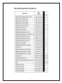
1
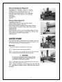
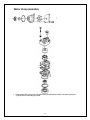
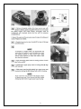
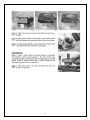
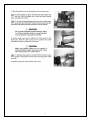
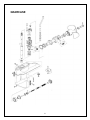
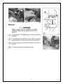
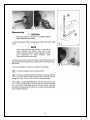
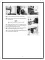
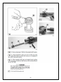
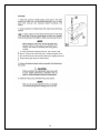
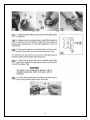
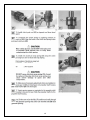
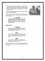
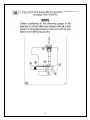
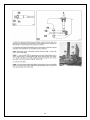
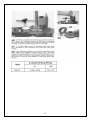
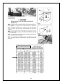
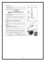
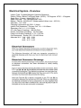
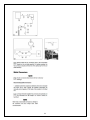
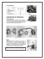
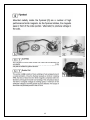
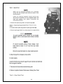
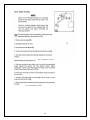
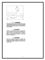
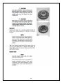
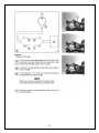
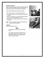
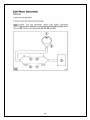
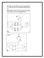
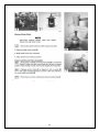
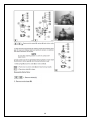
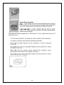
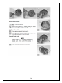
SECTION 6 - GEARCASE General Precautions Before performing any service work on the gearcase, read and understand the Service Safety section at the beginning of this manual. Full servicing of the gearcase requires manufacturer special tools. Follow all special tool requirements as specified. Substituting special tools with those not provided by the manufacturer may result in severe personal injury, equipment or engine damage, or faulty service work. Perform bearing removal and installation operations exactly as specified to avoid damage to the bearing or housing during pressing operations. Replace locking fasteners when their locking feature becomes weak. Use only factory replacement parts. When using compressed air to clean or dry parts, make sure air supply is regulated not to exceed 25 psi [172 kPa I 1.76 kg/cm']. 1 Special Equipment Required 2 3 Water Pump Assembly 1. Disassemble the water pump component as illustrated and verify the kit parts match the originals before discarding old parts. 4 5 6 7 GEARCASE 8 9 10 11 12 13 4. Install specified socked (6) Part No. 345-72232-0 and wrench (7) (Part No. 346-7223-1-0). Hold bevel gear B nut with wrench and turn driveshaft clockwise to tighten the nut. Torque bevel gear B nut to specification 14 15 16 17 18 19 Backlash Special tools are required for measuring backlash. The following describes how to measure and correct backlash in the Raider 40 outboard. 20 21 22 Dial Gauge Setting 23 Gearcase Needle Bearing: Note: Obtain needle roller bearing puller kit: P/N: 3C8-72700-0. 24 25 26 27 SECTION 7 – ELECTRICAL SYSTEM General Precautions Before performing any service work on the electrical system, read and understand the Service Safety section at the beginning of this manual. Use the manufacturer and special tools as indicated during servicing of the electrical system. Avoid electrical shock: • Do not handle spark gap tester leads during performance testing. • Do not touch ignition coils, exciter coil, pulser coils, or alternator coils while the engine is cranking or running. Use the spark gap tester to prevent the engine from starting when performing static ignition performance tests. Use caution when performing tests with the engine cover removed. Do not wear loose clothing or jewelry. Keep hair, hands, and clothing away from the flywheel and other moving parts. After repairs are complete, make sure all ignition and electrical leads are properly routed and clamped in their original positions. Replace locking fasteners when their locking feature becomes weak. Use only factory replacement parts. Always inspect and test the start-in-gear prevention system before returning engine to customer. 28 General Precautions Before performing any service work on the Raider electrical system, read and understand the Service Safety section at the beginning of this Service Manual. Use the manufacturer and special tools as indicated during servicing of the electrical system. Avoid electrical shock: Do not handle spark gap tester during performance testing. Do not tough ignition coils, exciter coil, pulser coils or alternator coils while engine is cranking or running. Use the spark gap tester to prevent the engine from starting when performing static ignition performance tests. Use caution when performing tests with the engine cowling removed. Do not wear loose clothing or jewelry. Keep hair, hands, and clothing away from the flywheel and other moving parts. After repairs are complete, make sure all ignition and electrical leads are properly routed and clamped in their original positions. Replace locking fasteners when their locking feature becomes weak. Use only COTS factory parts (Mercury, Nissan or Tohatsu) or Raider replacement parts. Always inspect and test the start-in-gear prevention system before returning engine to mission readiness. Always disconnect battery when not in use. 29 Electrical System - Overview Ignition Type: Flywheel Magneto Capacitor Discharge Ignition Timing: Before Top Dead Center (BTDC) – 25 Degrees ATDC – 2 Degrees Spark Plug: Pulstar – Model SBE 1/10 Spark Plug Gap: .033 (No larger than .050) Battery: Part No. 365-265-001 (Raider sealed Lithium Iron – 265 CA) Alternator: 12V 80W Charging Performance @ 5500 – 5 Amps Ignition Coil Resistance – Primary Coil: 0.2 – 0.3 KOhms Secondary Coil: 4.1 – 6.1 K Ohms CD Unit Output (Cranking): 198-220 DVA Exciter Coil Output (Cranking): 100 DVA Mim Pulser Coil Output (Cranking): 4.75 – 5.0 DVA Coil Resistance – Exciter Coil: 130-195 Ohms Alternator W-Y: Y-W 0.65 - 0.98 Y-B 0.31 – 0.47 W-B – 0.37 – 0.55 30 31 Troubleshooting - Electrical 32 Internal battery 33 Raider has: (1) CD Unit; (2) Coil Plate; (3) Exciter Coil; (4) Ignition Coil; (5) Pulser Coil; (6) Alternation/Lighting coil. 34 35 36 Battery Care and Maintenance The Raider 40 outboard motor has a battery located internal, located under the cowling. This battery is a fully sealed lithium-iron battery shown below. 37 The battery has one plug with two connectors (+) and (-). It is constructed that it can be plugged into the mating connector one way. Battery Size: Length: 5.83 inches x Width 2.63 x Height 4.13 inches Weight: 2.5 pounds Cold Cranking Amps: 270 Polarity: (+) (-) Charging System: Output of 13.1 Volts Lithium-iron: 18 Ah PbEq 12V; eq, “L” polarity, Sealed Fastening System: Slot in base of battery receptacle; single screw at top. General Procedures Inspection Inspect battery case for damage Inspect connector for corrosion Inspect cables Check battery mounting Cleaning Disconnect and remove battery Clean battery, connectors Wash with water and let dry Place dielectric grease on both side of connector Replace battery, tighten screw. Do not plug in connector until ready for use Ignition System 38 When repairs are complete; make sure all ignition and electrical Leads are properly routed and clamped in their original systems And the in-gear prevention system must be tested prior to delivering to units. 39 If you have problems stopping Raider outboard proceed directly to test 2 – Stop Circuit Test Ignition System Performance Testing Flow Chart 40 41 Test 2 – Stop Circuit Test 42 Stop circuit malfunction can cause Raider not to start or preventing it from stopping. Several component failures can cause the stop circuit to malfunction. Use this flow Chart to isolate and repair all component failures. Note: After you complete each stop circuit test, refer back to this flow chart for the Next step. Test 2b. Stop Circuit Emergency Stop Switch Test 43 The emergency stop switch test is used to determine whether it is functioning normally. Note: Make sure all electrical terminals are connected during this test except those that are noted in the test procedure. Check for continuity between chassis ground and the ground connection for the magneto plate, CD Unit, and ignition coils before conducting the following procedure. All continuity tests must be conducted or you may damage the meter. Remove plug from Raider battery. 44 Test 3 – Exciter Coil Test 45 NOTE Make sure all electrical terminals are connected during this test except those that are noted in the test procedure. Check for continuity between chassis ground and he ground connection for the magneto place, CD Unit, and ignition coils before conducting the following procedure. Reference the following electrical drawings for the exciter coil test. The pulser and alternator coils have been removed from both illustrations for clarity. Test 3 – Exciter Coil Test 46 The exciter coil test is used to determine the output voltage, in DVA, from the exciter coil Located on the coil plate assembly (2) to the CD Unit while you are cranking the engine. Disconnect terminals 4, 5, 8 and 9. Set the digital multimeter to ohms and connect the leads between the following Terminals to read the resistance of the exciter coil: Connect multimeter between 4 and 8 terminals. The meter should read 200 – 300 ohms +/- 25% If the resistance is not within the indicated range, replace the exciter coil set. See Ignition System Repair Procedures – Exciter Coil. After repairs are made, return to Ignition System Performance Flow Chart. If the resistance is within indicated range, proceed to the next step. Connect multimeter between these terminals 4 and 8; set the analog multimeter to “400” on the “DVA” scale. Connect the RED tester lead to terminal “4” and BLACK tester lead to termanal “8”. Attach lanyard to emergency stop switch. Crank Raider outboard engine. At cranking RPM, the tester should show the following results: 100 DVA Minimum. If the exciter coil test results are not within the acceptable range, replace the exciter coil set. See Ignition System Repair Procedures Exciter Coil. Reconnect all wires disconnected during test. Return to flow chart. Test 4. Raider Pulser Coil Test NOTE Make sure all electrical terminals are connected during this test except those that are noted in the test procedure. 47 Check for continuity between chassis ground and the ground connection for the magneto plate, CD Unit, and The Raider pulser coil test is used to determine the output voltage, in DVA, from the pulser coil (1) located on the coil plate assembly (2) to the CD unit (3) while you are cranking the engine. Disconnect the following terminals: 4, 5, 6, 7, 8 and 9 Set the digital multimeter to ohms and connect the leads to test the resistance of the coil. Connect multimeter between 6 and 8 terminals. Multimeter should indicate 30 – 45 ohms +/- 25% If the resistance is not within the indicated range, replace the Raider pulser coil. See Ignition System Repair Procedures – Pulser Coil. After repairs are made, return to Ignition System Performance Testing Flow Chart. If the resistance is within the indicated range, proceed to the next step. Set the analog multimeter to “20” on the “DVA” scale. Insert the banana plug of the RED tester lead into the meter connection labeled “DVA” and the banana plug of the BLACK tester lead into the meter connection labeled “COM.” Black lead to Terminal 6 and Red Lead to Terminal 8. Attached lanyard to emergency stop switch. Crank engine. At the cranking RPM; the tester should show the following results – minimum of 3.0 DVA If the pulser coil test results are not within the acceptable range, replace the pulser coil 48 set. See Ignition System Repair Procedures – Pulser Coil. Reconnect all wires disconnected during test. Test 5. CD Unit Output test – Cranking RPM NOTE Make sure all electrical terminals on Raider are connected during this test except those that are noted in the test procedure. Check for continuity between chassis ground and the ground connection for the magneto plate, DC Unit and Ignition Coil before conducting the following procedure. Reference the electrical drawings for the CDE Unit Output Test – Cranking RPM. [12] The CD Unit Output Test – Cranking RPM is used to determine the output voltage, in DVA, from the CD Unit (1) to the ignition coil (2) while you are cranking the engine. 1. Remove two spark plug leads and remove spark plugs (3) [13] 2. Adjust spark gap tester (1) to 7/16 inches - 11 mm 3. Connect each spark plug lead to spark gap tester (2) 4. Secure spark gap tester to a clean ground on engine block. 5. Secure spark plug gap tester to a clean ground on engine block. To avoid possible shock hazard, do not handle Ignition coils or spark gap tester during cranking tests. 49 NOTE To prevent possible arcing of high voltage, route tester leads At least 2 inches from any metal surface. Ground unused test leads to a clean engine ground. 5. Set the tested to “400” on the “DVA” scale. Insert the banana plug of the RED tester head into the meter connection labeled “DVA” and the banana plus of the BLACK tester lead into the meter connection labeled “-COM.” Connect the BLACK tester lead to terminal (3). [12] 8. Carefully slide the RED tester into the bullet connector (terminal 4) sleeve until it makes contact with the terminal. NOTE DO NOT disconnect the CD Unit output connector (terminals (4) and (8). Damage to the CD Unit may result. 9. Attach lanyard to emergency stop switch. 10. Crank engine At cranking RPM, the tester should show the following result for each CD Unit output – 100 DVA minimum. If the test results for any CD Unit output is not within acceptable range, replace the CED Unit. See Ignition System Repair Procedures – CD Unit. Reconnect all wires disconnected during test. Return to flow chart. 50 0.2 – 0.3 ohms +/- 25% 4.1 – 6.1 kohms +/- 25% 51 52 Ignition System Repair Procedures 53 54 55 56 57 58 59 60 61 62 63 64 65 If meter does not indicate battery voltage, repair or replace cable between (12) and (14). If meter indicates battery voltage, go to next step. 13. Connect RED tester lead to main button starter switch and push Raider start button. 66 Note: After disassembly prior to assembly spray “Corrosion Zero” on all parts. 67 68 The Raider 40 Original Length (a) is 0.295 inches (7.5 mm). Repair Limit (b) is 0.177 inches (4.5 mm). 69 70 71 72 The meter should indicate the following resistance: Y-W: 0.65 – 0.98 73 Y-B : 0.31 – 0.47 W-B: 0.37 – 0.55 74 75 Charging System - Repair Procedures 76 77 78 79