1
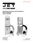
Security Engineered Machinery Co., Inc.
OPERATIONAL & MAINTENANCE MANUAL
SEM Model 200/650
Disintegrator
As of September 1, 2009
Rev. 0
Security Engineered Machinery Co., Inc
NATIONWIDE SERVICE
Phone Toll Free: 1(800)225-9293
Email: [email protected]
Fax: (508)366-6814
Website: WWW.SEMSHRED.COM
Table of Contents
Index---------------------------------------------------------------------------------------------------2
Important Safety Processes-------------------------------------------------------------------------3
General Assembly Drawing-------------------------------------------------------------------------4
Power Supply Requirements------------------------------------------------------------------------5
Plug and Receptacle Information ------------------------------------------------------------------6
Installation Instructions----------------------------------------------------------------------------7-8
Operating and Troubleshooting--------------------------------------------------------------------9
Feed Information (See also label on top of machine) ------------------------------------------10
Maintenance (Changing of knives and screen) ---------------------------------------------11-12
(Sharpening knives see diagram page 12)
Cutting Chamber Assembly-----------------------------------------------------------------------13
Rotor and Bed knife Settings----------------------------------------------------------------------14
Knife Sharpening Settings-------------------------------------------------------------------------14
Electrical Panel--------------------------------------------------------------------------------------15
Electrical Schematic--------------------------------------------------------------------------------16
Options / Spare Parts-------------------------------------------------------------------------------17
Instructions for the 650C in rear of this manual
For NATIONWIDE SERVICE Call 1(800)225-9293
2
***IMPORTANT SAFETY PROCEDURES***
Your new SEM Model 200 incorporates powerful, heavy duty cutting mechanisms, serious and
permanent injury may result if proper precautions are not followed.
1. This equipment should never be operated by children or individuals that
are untrained or incapable of understanding these safety precautions!
2. Do not reach into the feed opening for any reason! Never insert fingers,
hands, other extremities, or objects not meant to be crushed into the feed
opening!
3. Do not operate or come into close proximity to this equipment wearing
loose clothing, neckties, dangling jewelry, or long hair which may become
entangled in the crushing chamber.
4. Maintenance or repair of this equipment should be performed only by
trained, authorized service personnel.
5. Always disconnect electric power (unplug) before removing or opening
any cover or other panels providing access to the internal mechanisms.
Important:
If you over feed the Disintegrator or have an Emergence and need to shut down the machine without using
Time Shutdown open the front door of the disintegrator cabinet.
Warning:
Opening the front door to bypass the Time Shutdown can result in a jammed cutting chamber or damage
to the Cutting Chamber.
Warning:
After inserting documents or other materials close Feed Door.
For NATIONWIDE SERVICE Call 1(800)225-9293
3
General Assembly Drawing
Cartridge Filter
Feed Door
On-Off Selector Switch
With Time Shutdown
Disintegrator Cabinet
Vacuum Cabinet
For NATIONWIDE SERVICE Call 1(800)225-9293
4
Power Supply Requirements
MODEL 200
For Connecting to Single Phase Power
FOR 115 VOLT/1 PH /60 HZ
Note to Installer:
The Model 200 Disintegrator System has been supplied with a power cord and male plug for 20 amp
service.
The male plug is a NEMA # 5-20P and requires a female connection as noted below.
Ref: NEMA 5-20R.
FOR 220 VOLT / 1 PH / 50-60 HZ
Note to Installer:
SEM has provided a power cord with male plug for 15 amp service.
The male plug is a NEMA # 6-15P and requires a female connection as noted below.
Ref: NEMA # 6-15R
On overseas applications, a round pin type plug with ground (32 amp rating) has been supplied.
OPTIONS:
A)
If it doesn't fit your power receptacle, cut off and replace plug to conform to local electrical
requirements.
B) Cut off plug and hardwire to a power disconnect switch.
For NATIONWIDE SERVICE Call 1(800)225-9293
5
Plug and Receptacle Information
SEM normally supplies a male plug and cord prewired to the disintegrator unit for single phase.
The NEMA Configurations are as followed:
Model 200
115 volts – 125 volts single phase SEM supplies a NEMA #5-20P the
customer needs to supply a NEMA #5-20R receptacle 20 amps
220 volts – 250 volts single phase SEM supplies a NEMA #6-15P the
customer needs to supply a NEMA #6-15R receptacle. 15 amps
Note:
Any over sea or European shipments at 220 volts single phase 50 cycles must supply their own
plug unless otherwise specified at time of the order.
For NATIONWIDE SERVICE Call 1(800)225-9293
6
Installation Instructions
DISINTEGRATOR LOCATION:
The Model 200 can be located in an office area within 6 feet of a wall receptacle with a dedicated 20 amp
line. It is recommended that the machine be 3 to 4 inches away from the wall for proper ventilation.
1) Place Vacuum Cabinet next to the Disintegrator Cabinet (on the left side) so the handles are next to
each other then open doors on the cabinets and feed vacuum hose thru hole in the bottom of the
right side of cabinet and connect to the transition in the disintegrator cabinet.
Transition
Vacuum
Cabinet
Disintegrator
Cabinet
2) Plug Vacuum cabinet into the back of the Disintegrator Cabinet. Shredder will be plugged in when
received.
Blank
Plug
Vacuum
Plug
Disintegrator
Cabinet
Vacuum
Cabinet
For NATIONWIDE SERVICE Call 1(800)225-9293
7
Installation Instructions
Electrical Wiring:
(See Diagrams on pages 14, 15)
A) The machine includes an appropriate power cord and 20-amp male plug. The unit is activated by
a top mounted selector switch with indicator light.
B) Access to the cutting chamber for service is provided by the main cabinet door. A safety unit
switch activated by the main door prohibits operation when door is open.
C) The Model 200 has been wired per your specification. The motor supplied operates on single
phase voltage.
Note: Some motors have manual overload reset button on motor, others are automatic. (Each
machine will be clearly marked.)
D) If for any reason the machine is rotating in the wrong direction remove metal plate on motor
and change leads as shown on plate diagram.
Note: Motors are normally dual voltages, 115/230 but can only be operated at the specific voltage as
wired at the factory, if voltage change is required in the field contact factory for proper instructions.
Note: Power required 115 volt /1 PH /60 CY 20 amps Disintegrator motor 9.6 amps, Vacuum motor
11.0 amps.
E)
220 volt /1 PH / 60 CY -20 amps Disintegrator motor 4.9 amps, Vacuum motor 5.5 amps.
F) The Disintegrator System is supplied with a power cord and plug. The vacuum and
shredder are also supplied with plugs for cabinet receptacles.
For NATIONWIDE SERVICE Call 1(800)225-9293
8
Operating and Troubleshooting
Please read this section carefully, most problems occur during the first hours of operation. Most
problems can be eliminated by careful review of the operating, maintenance and recommended
service instructions.
A) The model 200 has been shipped complete tested and is operational when received.
B) The Model 200 requires a dedicated line equipped with a 20 amp receptacle. (See page 3
options)
C) Once positioned, verify vacuum is connected, all access points are closed. By turning selector
switch, the unit will start and will illuminate the green operating lamp.
D) The Model 200 was designed to destroy plastics, film and light volumes of paper products. But
as with any type of office machine, it can be overloaded or jammed if overfed. Product destruction
rate depends on the material, size and desired particle size. When feeding the concept of "less is
more" by feeding the unit less volume more often will result in better feed rates and reduce
the operating costs.
E) All Model 200’s units are equipped with time shutdown to help prevent jamming of the disintegrator.
When Selector Switch is in the OFF DELAY position the disintegrator will run for an additional 60
seconds to clear the chamber. This will help to prevent jamming of the unit which would require
some disassembly to gain access to the cutting are.
Important:
If you over feed the disintegrator or have an emergence and need to shut down the machine open
the front door of the disintegrator cabinet.
Warning:
Opening the front door to bypass the Time Shutdown can result in a jammed cutting chamber or
damage to the Cutting Chamber.
F) To clear a jammed or locked rotor:
a. Make sure selector switch is in OFF position
b. Unplug power cord
c. Open front door of disintegrator cabinet
d. Remove plate on front hopper to access the cutting area
e. Remove loose product
f. Rotate rotor counter clockwise by means of the drive belt by hand to clear clogged material
To restart:
a. Re-secure plate on front hopper
b. Re-plug power cord
c. If necessary, reset circuit breaker switch or motor contactor, located above motor
d. Close main door
e. Turn selector switch to "on" start position
NOTE: Repetitive jams also can be a result of knives that require sharpening. If machine has
no power, reset circuit breakers on electrical panel located above motor.
For NATIONWIDE SERVICE Call 1(800)225-9293
9
Important Feeding Information
1. Before introducing any destruction material into feed slot, the Model 200 and its Vacuum must be
turned on and operating. The material collection vacuum must be checked periodically and emptied
for the continued operation.
2. Destruction Material: The Model 200 is capable of processing a variety of materials safely and
effectively. Products that can be destroyed include products with light metals, plastics and paper. Listed
below are products tested if you are trying to destroy anything that is not listed below and would like to
verify contact SEM's Customer Service at 1-800-225-9293 before use.
3. Paper Destruction: The Model 200 is not a Shredder but a Rotary Knife Mill, which dictates how
the unit is fed and the rate it can be fed at. Rule of thumb, "Less is More" which creates steady
output without over feeding. Feed rate is 4-5 sheets approximately every 10 seconds averaging
18-20 pounds* of paper per hour. (Approximately 4 reams of paper)
4. When destruction is complete, allow the Model 200 and vacuum to operate an additional 60
seconds after the last feed of material. This will prevent build up in the cutting area and
evacuation line, ensuring proper operation for the next user.
5. Vacuum Collector as with a conventional shredder. The Model 200’s waste collection bag must
be periodically emptied for proper operation. Bag capacity is 35 Gallons or approximately 200
sheets (5 reams) of paper.
Note:
For optimal sound reduction after inserting documents or other materials close Feed Door.
*Destruction rates of paper are based on 20 lb. bond 8-1/2” x 11” using 3/32” destruction screen, rates
can change depending on the screen size.
Other rates of material are:
CD ROMS at 3-5 per feed approximately every 15 seconds
Floppies at 3-5 per feed approximately every 20 seconds
Zip disks at 1-2 per feed approximately every 35 seconds
Audio Cassettes at 1 per feed approximately every 30 seconds
Key Tape strips up to10 inches in length, 6 per feed lot
For NATIONWIDE SERVICE Call 1(800)225-9293
10
Maintenance
Important / Caution: Unplug Cord from Receptacle
A) Belt Adjustment:
Open front door and remove top cover (be shore to unplug top cover) the motor is mounted on
a slotted frame. Loosen four (4) mounting bolts and adjust motor toward rear of machine to
tighten or move forward for belt removal. Proper belt tension is determined by extending
thumb pressure on belt causing a slight bow on slack side. This should be no more than 1/2".
IMPORTANT: Belt should be checked and tightened if required after first two (2) days of operation,
after that check monthly.
B) Lubrication:
Grease fittings are accessible when cabinet cover is opened. Grease twice yearly with Gulflex
"A", multi-purpose or equivalent, grease fittings are located on rotor bearings (C-14).
KNIVES:
For full efficiency, knives should be sharpened from two to five times a year, depending on use. If
for example, your knives require sharpening after three months of operation, your sharpening
schedule should be every three months. It is highly recommended that a spare set of knives be
available for your Disintegrator.
Changing Knives: (See diagram pages 9 & 10)
A) Unplug cord from receptacle/lock out power from device
B) Remove top cabinet cover
Note: When cover is open a safety limit switch contact opens, this insures that no one accidentally
starts the disintegrating if power cord has not been unplugged.
C) Remove the Feed hopper from cutting chamber (unplug cord)
D) Prior to removing or replacing the rotor knives, back off bed knife adjusting screws. Cover the
edge of each knife with a heavy gauze tape such as scotch filament or cloth tape. Remove all
knives prior to replacing any of the knives.
E) Bed Knife:
First remove bolts, (2) on the right, and (2) on the left of each of the aluminum deflectors. Remove
three bed knife bolts from each bed knife. Remove bed knife holder plate and bed knife. Take
spare bed knife and insert exactly the way the dull knife came out. Insert bed knife bolts and hand
tighten. Finally replace the rotor knives. Remove the tape covering the edge of both rotor knives
and adjust the distance between the rotor knife and bed knife by manually rotating rotor in reverse
direction. Adjust to a minimum of .001 to .002 inch clearance using feeler gauge.
Note: Tool kits are available from Factory
For NATIONWIDE SERVICE Call 1(800)225-9293
11
Maintenance
Knives Continued:
F) Caution: Before tightening bed knife securely determine that the knives are set properly by
manually rotating rotor in the operating direction to insure that no rotor knife touches the
bed knife.
Knife Torque's
Knife Bolt Torque's required: 45 FT lbs.
for bed knives 50 FT lbs. for rotor knives
Sharpening Knives:
(See Diagram Page 12)
Knives may be sent to Security Engineered Machinery (SEM) for sharpening or they may be
sharpened by a capable machine shop in your area. When sharpening the rotor knives must be
sharpened as a set to maintain proper tolerance between the bed knives. If knives are badly nicked
the machine should not try to eliminate the entire nick so as to conserve the edge and prolong knife
life. The knives will function very well with nicks after sharpening.
Changing a Screen:
A)
Unplug power cord
B)
Open front main door
C)
Remove nuts from the combination screen/transition
D)
Lower screen
E)
Insert new screen and nuts, re-tighten
F)
Put transition back into place
G)
Close front access door
If Disintegrator will not start:
A) Front access door is fully closed to activate safety switch
B)
Top cover safety switch is fully closed or depressed
C) Motor thermal overloads and a circuit breaker are located on the machine control panel,
located in the rear of the cabinet. As a safety feature, the units in the controls may "kick out" after
an overload; simply reset the control (s) to re-start machine operation.
For NATIONWIDE SERVICE Call 1(800)225-9293
12
Cutting Chamber Assembly
ITEM
1
2
3
4
5
6
7
8
9
10
12
13
14
15
16
17
19
20
21
22
23
24
25
26
27
28
29
30
31
32
33
34
35
QTY
1
1
1
1
1
2
2
1
18
32
4
4
6
6
14
6
8
9
4
4
1
1
2
8
3
6
6
4
8
2
1
2
1
DESCRIPTION
Left Side Plate
Right Side Plate
Bed Knife support
Rear Deflector
Front Deflector
Bed Knife Seat
Flange Bearing
Rotor 3 Blade
3/8-16x1-1/4 Hex Head Grade 5
3/8 Lock Washers
3/8 Flat Washers
3/8-16 Hex Nut
¼” Roll Pin x 1”
5/16-18x1-1/4 Hex Head
5/16 Lock Washers
3/8-16x1-1/2 Socket HD Cap Grade 8
5/16 Flat Washers
3/8-24x3/4” Socket HD Cap Grade 8
¼-20x1-1/4” Square Head
¼-20 Hex Nut
Bed Knife Clamp (Front)
Bed Knife Clamp (Rear_
Bed Knife
3/8-16x1-1/2” Hex HD Cap Grade 5
Rotor Knife
3/8 Hardened Washer
5/16-18x1-1/4” Socket Set Screw
3/8-16x1-1/2” Socket Set Screw
5/16-18 Hex Nut
5/16-18x1-1/2” Socket Set Screw
½-13x3/4 LG-Hex HD Cap Screw Grade 8
Motor Shim
Bed Knife Support
PART/DWG#
3-20-6531-00
3-206532-00
3-20-6165-00
3-20-6168-00
3-20-6167-00
3-20-6164-00
4-20-6991-SL
2-20-6274-00
2-20-6275-00
4-20-6271
320-6165-AB
For NATIONWIDE SERVICE Call 1(800)225-9293
13
Recommended Rotor and Bed Knives Settings
Knife Sharpening Settings
A= Minimum distance 2.625”
B= Bed knives must be held alike and
parallel in sets within 0.010”
C= Rotor knives must be held alike and
parallel in sets within 0.002”
NOTES ON KNIFE GRINDING:
1. After regrinding number of times, the knives must be checked to be sure that there
will be adjustment left in the bed knives. The general rule is to place a rotor knife
and bed knife back as shown above, and measure the total dimension "A" distance
2.
If dimension "A" is close to minimum, a new set of knives should be ordered
from the S.E.M. Customer Service Department
Recommended Rotor and Bed Knife Re-sharpening
For NATIONWIDE SERVICE Call 1(800)225-9293
14
Electrical Panel
1
2
4
3
Item
1
2
3
4
5
6
7
8
5
Qty.
1
1
10
1
1
1
1
0
6
8
7
Description
Contactor
Main Circuit Bracker
Termanal Board 1-9 with one spare
Timer for Time Shutdown
Relay to Activate Timer
Motor Circuit Bracker
Vacuum Circuit Braker
Shredder Circuit Bracker (only on DS Models)
Part Number For NATIONWIDE SERVICE Call 1(800)225-9293
15
Electrical Diagram
For NATIONWIDE SERVICE Call 1(800)225-9293
16
Options and Spare Parts
Options:
ϖ Maintenance Kit
P/N DMK200
Kit includes:
Spare Set of Knives Shipping
Case
Lifetime Sharpening Knife
Hardware
Spare Parts
ϖ Standard Knives
P/N 391200K/3
3 Rotor / 2 Bed
ϖ Perforated Security Screens
P/N 341201332
3/32" Dia.
Services
ϖ Knife Sharpening
ϖ Service Contracts
Contact our
Customer Service Department
For details at 1-800-225-9293
Or order online at vvww.semshred.com
For NATIONWIDE SERVICE Call 1(800)225-9293
17
OPERATIONAL & MAINTENANCE MANUAL
Confetti Waste Collector Model 650C
As of January 1, 2008
Security Engineered Machinery Co., Inc.
NATIONWIDE SERVICE
Phone Toll Free 1(800)225-9293
Email: [email protected]
Fax: 1(508)366-1671
Website: WW.SEMSHRED.COM
For NATIONWIDE SERVICE Call 1(800)225-9293
18
TABLE OF CONTENTS
Table of Contents/Specifications------------------------------------------------------------------------------21
Warnings------------------------------------------------------------------------------------------------------22-23
Grounding Instructions------------------------------------------------------------------------------------------24
115V Operation---------------------------------------------------------------------------------------------------24
230V Operation---------------------------------------------------------------------------------------------------25
Unpacking/Contents----------------------------------------------------------------------------------------------26
Assembly-------------------------------------------------------------------------------------------------------27-28
Wiring Diagram---------------------------------------------------------------------------------------------------29
Parts Breakdown -------------------------------------------------------------------------------------------------30
Parts List-------------------------------------------------------------------------------------------------------31-32
SPECIFICATIONS
-DC-650C
Stock Number --------------------------------------------------------------------------------------------708640C
Blower Wheel Diameter---------------------------------------------------------------------------------------9 ½”
Sound Rating at 3 feet----------------------------------------------------------------------------------------88dB
Hose Diameter-----------------------------------------------------------------------------------------------------4”
Air Flow (CFM) ------------------------------------------------------------------------------------------------650
Velocity at 4” (FPM) ----------------------------------------------------------------------------------------6,750
Static Pressure (inch of water) --------------------------------------------------------------------------------6.3
Bag Diameter---------------------------------------------------------------------------------------------------13.9”
Filter & Collector Bag Length-------------------------------------------------------------------------------33.5”
Collector Bag Capacity (cu. Ft.) ------------------------------------------------------------------------------2.9
Overall Dimensions------------------------------------------------26-1/2” x 14” x 61-1/2” w/Canister Filter
Motor (TEFC) ---------------------------------------------------------1 HP, 1Ph 115/230V, Previewed 115V
Net Weight (approx.) ------------------------------------------------------------69 lbs. without Canister filter
The Specifications in this manual are given as general information and are not binding. Group reserves
the right to effect, at any time and without prior notice, changes or alterations to parts, fittings, and
accessory equipment deemed necessary for any reason whatsoever.
For NATIONWIDE SERVICE Call 1(800)225-9293
19
WARNING
READ THE FOLLOWING SAFETY TIPS - BEFORE OPERATING THIS
VACUUM-TYPE COLLECTOR
• REFER TO THE ELECTRICAL POWER REQUIREMENTS
• DO NOT USE THIS UNIT OUTDOORS OR ON WET SURFACES
• USE ONLY RECOMMENDED ATTACHMENTS SUPPLIED
• DO NOT PULL THIS UNIT BY THE ELECTRICAL CORD
• DO NOT HANDLE CORD/PLUG WITH WET HANDS
• DO NOT USE WITHOUT WASTE BAG OR FILTER IN PLACE
• DO NOT OPERATE UNIT WITHOUT HOSES IN PLACE
• CAUTION - HAZARDOUS MOVING PARTS INSIDE
• DO NOT USE COLLECTOR FOR ANYTHING BUT PAPER OR WOODEN
PARTICLES. METAL ITEMS CAN CAUSE SPARKS
• ELECTRICALLY 'GROUND' THE 'WASTE COLLECTOR, AS OUTLINED IN
THE ELECTRICAL SECTION OF THIS MANUAL
For NATIONWIDE SERVICE Call 1(800)225-9293
20
WARNING
To reduce the risk of injury from moving
parts, always keep inlet connected to a
flexible hose. Failure to comply may result
in serious injury!
Electrical Connections
To clean the filter turn the handle a couple
rotations so the dust falls into the collector bag.
Removing the Collector Bag
CAUTION
Wearing a particle mask/respirator for
protection against fine dust particles during
cleaning is highly recommended.
WARNING
All electrical connections must be done by a
qualified electrician. All adjustments or
repairs must be done with the dust collector
disconnected from the power source,
unplugged. Failure to comply may result in
serious injury!
The DC-650C dust collector is rated at
115/230V, Prewired 115V. Use a plug and
outlet rated at least 20 amps. The circuit for the
machine should also be protected by at least a
20 amp circuit breaker or fuse. Keep in mind
that a circuit being used by other machines,
tools, lights, heaters, etc. at the same time will
add to the electrical load. A dedicated circuit to
the dust collector will give you the best results
since dust collectors are generally used at the
same time other toots are running.
Before hooking up to the power source, make
sure that the switch is in the off position.
Turning the Machine On & Off
Before hooking up to the power source, make
sure that the switch is in the off position.
The dust collector can be turned on by flipping
the start switch up. Flip the switch down to turn
the dust collector off. There is a removable key
that can be used to lock the machine in the
"OFF" position.
Maintenance
1. Disconnect the machine from the power
source, unplug.
2. Remove the collector bag by pushing the
ring of the collector bag upwards at an angle
and pulling the bag and snap ring out.
3. Empty the contents into an appropriate
container.
Motor
Inspect the motor fan and blow out (with low
pressure air hose) or vacuum any accumulation
of foreign material in order to maintain normal
motor ventilation.
Connecting the Dust collector to a
Machine
Use the proper type hose to connect the dust
collector to the machine being operated. Dryer
vent hose is not acceptable for this purpose.
Contact your nearest JET distributor for the full
l i ne o f J ET D us t Col l ec tor H oses and
Accessories. Customize your installation and
obtain maximum performance with JET's dust
hoods, hoses, clamps, fittings, and blast gates.
You can also purchase the JET "Dust Collection
Basics Video" stock # JW1050V through your
JET Distributor
Grounding the Dust Collection System
WARNING
Never perform maintenance on this machine
before turning switch off and removing plug
from power source, unplug.
Failure to comply may cause serious injury!
Cleaning the Filter
Clean both the filter and collector bag frequently to
keep the collector's performance at its optimum.
The dust collection system includes the dust
collector and the hose, or duct work you use to
connect the tools. The dust collector is grounded
though the ground wire in the cord. The hose or
duct work you use to connect the tool to the dust
collector must also be grounded. To assist in
grounding your system you can purchase the JET
"Dust Collector Grounding Kit" stock # JW1053,
and also the JET "Dust Collection Basics Video"
stock ft JW1050V through JET Distributors.
For NATIONWIDE SERVICE Call 1(800)225-9293
21
Grounding Instructions
Caution: This tool must be grounded while in use to protect the operator from electric shock.
In the event of a malfunction or breakdown, grounding provides a path of least resistance for
electric current to reduce the risk of electric shock. This tool is equipped with an electric cord
having an equipment-grounding conductor and a grounding plug. The plug must be plugged
into a matching outlet that is properly installed and grounded in accordance with all local codes
and ordinances.
Do not modify the plug provided. If it will not fit the outlet, have the proper outlet installed by a qualified
electrician.
Improper connection of the equipment-grounding conductor can result in a risk of electric shock. The
conductor, with insulation having an outer surface that is green with or without yellow stripes, is the
equipment-grounding conductor. If repair or replacement of the electric cord or plug is necessary, do
not connect the equipment-grounding conductor to a live terminal.
Check with a qualified electrician or service personnel if the grounding instructions are not
completely understood, or if in doubt as to whether the tool is properly grounded. Use only three wire
extension cords that have three-prong grounding plugs and three-pole receptacles that accept the
tool's plug.
Repair or replace a damaged or worn cord immediately.
115 Volt Operation
As received from the factory, your dust collector is ready to run at 115 volt operation. This dust collector,
when wired for 115 volts, is intended for use on a circuit that has an outlet and a plug that looks the one
illustrated in Figure A. A temporary adapter, which looks like the adapter as illustrated in Figure B,
may be used to connect this plug to a two-pole receptacle, as shown in Figure B if a properly
grounded outlet is not available. The temporary adapter should only be used until a properly
grounded outlet can be installed by a qualified electrician. This adapter is not applicable in
Canada. The green colored rigid ear, lug, or tab, extending from the adapter, must be connected
to a permanent ground such as a properly grounded outlet box, as Shown in Figure B.
THREE-PRONG PLUG
GROUNDING PRONG
Grounded
Outlet
Grounding Ear
Secured With
Screw
B
A
For NATIONWIDE SERVICE Call 1(800)225-9293
22
230 Volt Operation
If 230V, single phase operation is desired, the following instructions must be followed:
1. Disconnect the machine from the power source.
2. This dust collector is supplied with four motor loads that are connected for 115V operation, as shown
in Figure A. Reconnect these four motor leads for 230V operation, as shown in Figure B.
3. The 115V attachment plug supplied with the dust collector must be replaced with a UL/CSA listed
plug suitable for 230V operation. Contact your local Authorized JET Service Center or qualified
electrician for proper procedures to install the plug. The dust collector must comply with all local and
national codes after the 230V plug is installed.
4. The dust collector with a 230V plug should only be connected to an outlet having the same
configuration. No adapter is available or should be used with the 230V plug.
Important: In all cases (115 or 230 volts), make certain the receptacle in question is properly
grounded. If you are not sure, have a registered electrician check the receptacle.
2
230 Volt
3
LINE
4
LINE
FIGURE B
For NATIONWIDE SERVICE Call 1(800)225-9293
23
WARNING
Read and understand the entire contents of
this manual before attempting assembly or
operation of the dust collector!
Failure to comply may cause serious injury!
Unpacking
1.
Remove all contents from the shipping
cartons.
2.
Report any damage to your distributor.
3. Do not discard any shipping material until
after the dust collector has been assembled
and is running properly.
Contents of the Shipping Cartons
Canister Filter Box
1. Canister Filter
1. Handle
1. Bag of Hardware for handle
2. M10 Hex Nuts
2. M10 Flat Washers
1. M10 Lock Washer
4. Knobs
1. M8 Hex Nut
1. M8 Flat Washer
1. M8 Lock Washer
DC-650C
1. Base
1. Owner's Manual
1. Warranty Card
1. Motor/Fan Assembly
5. Collector Bags
1 Snap Ring
4. Casters
1. Support Cylinder
1. Bag of Assembly Hardware
4. M6x12 Hex Head Bolts
4. MG Lock Washers
4. MG Flat Washers
2. 3/8"-16 Acorn Nuts
2. 3/8" Hex Nuts
4. M10 Flat Washers
4. M8x12 Hex Cap Bolts
4. M8 Flat Washers
Tools Required for Assembly
2. 14mm Wrenches or Sockets
1. 10mm Wrench or Socket
1. 17mm Wrench
For NATIONWIDE SERVICE Call 1(800)225-9293
24
Assembly
WARNING
The dust collector must be disconnected
from the power source during assembly.
Failure to comply may result in serious
injury!
1. Place motor housing on the floor with the
motor fan facing upwards as shown in
Figure 1.
2. Attach support cylinder (A, Fig. 2) to the
motor housing with three M6x16 socket
head cap screws and three M6 flat washers
(B, Fig. 2).
3. Mount two fixed casters (C, Fig. 3) to the
appropriate end of base (D, Fig. 3) using
four M6 flat washers (E, Fig. 3), four M6
lock washers (F, Fig. 3) and four M6x12 hex
cap bolts (G, Fig. 3).
4. Mount two swivel casters (H, Fig 3) to the
appropriate end of the base with two 3/8"
hex nuts (I, Fig. 3), four M10 flat washers (J,
Fig. 3), and two 3/8" acorn nuts (K, Fig. 3).
5.
Mount support canister (L, Fig. 4) to base
(M, Fig. 4) with four M8x12 hex cap bolts
and four flat washers (N, Fig. 4).
6. Turn the dust collector over onto the
casters. Note: Make sure the base and
housing are relatively parallel. If not loosen
the screws that secure the support cylinder
to the motor and adjust as necessary.
Tighten all hardware.
For NATIONWIDE SERVICE Call 1(800)225-9293
25
7.
Place the canister filter so that it fits
Snugly over the housing and tighten
the four knobs (A. Fig 5).
8. Mount handle (B, Fig 5) to arm (C. Fig 5 )
with a M8 flat washer (D, Fig. 5). M8 lock
washer (E, Fig. 5), and a M8 hex nut
(F, Fig 5).
9. Thread a M10 hex nut (G, Fig 5) onto the
threaded rod found on top of the canister
filter followed by a M10 lock washer
(H, Fig. 5), and M10 flat washer (I, Fig 5).
10. Mount the arm (C, Fig. 5 ) to the threaded
rod on top of canister with one M10 flat
washer (J, Fig. 5) and a M10 hex nut
(K, Fig. 5).
11. Place snap ring (K, Fig 6) over the top of
plastic bag (L, Fig. 6) and fold over the bag
approximately three inches.
12. Insert the snap ring of the collector bag into
the bottom of the housing at an angle see
figure 7.
13. Pull down on the ring to make sure it “seals”
In the housing.
Note: Make sure the snap ring “snaps” into
place in the housing, and also that the plastic
bag hangs down approximately 3” so that
There are no air leaks.
For NATIONWIDE SERVICE Call 1(800)225-9293
26
For NATIONWIDE SERVICE Call 1(800)225-9293
27
Parts Breakdown for DC-650C Dust Collector W/Canister Filter
For NATIONWIDE SERVICE Call 1(800)225-9293
28
PARTS LIST FOR THE DC-650C DUST COLLECTOR W/CANISTER FILTER
Index No.
1
2
3
4
5
6
7
8
9
10
11
12
13
14
15
16
17
18
19
20
21
22
23
24
25
26
27
28
29
30
31
32
33
34
35
36
Part No.
Description
708737
331010
331043
331015
331042
ST049200
331011
TS-1540072
TS-1550071
TS-1551071
331014
150623
200076
TS-1550051
TS-1551061
TS-1540061
BR000052
TS-1503051
TS-1551041
TS-1550041
TS-1540041
331017
TS-1503031
331037
331047
331048
709565
422109W
MH422001
CA020010
994612
994613
MJ422001
M4220F
994532
IC422001
423023
412025W
410030
AB410033
Size
Filter
Shaft
Scraper
Plate
Support
Tapping Screw
Arm
Hex Nut
Flat Washer
Lock Washer
Bracket
Pad
Handle
Flat Washer
Lock Washer
Hex Nut
Rivet
Hex Head Bolt
Lock Washer
Flat Washer
Hex Nut
Strip
Hex Head Bolt
Jet Knob
Pad
Snap Ring
Clear Plastic Collection Bag
Impeller Housing
Motor
Starting Capacitor (not shown)
Centrifugal Switch (not shown)
Centrifugal Switch Rotor (not shown
Switch Box (not shown)
Motor Fan
Switch
Power Cord
Packing
Flange
Flange Packing
Impeller
M4x8
M10
M10
M10
M8
M8
M8
5-2
M6x20
M6
M6
M6
M6x12
M6x20
200MFD, 125V
9-1/2”
_____Qty
1
1
2
2
1
4
1
2
2
1
1
1
1
1
1
1
3
4
4
4
8
2
4
4
1
1
5
1
1
1
1
1
1
1
1
1
1
1
1
1
For NATIONWIDE SERVICE Call 1(800)225-9293
29
PARTS LIST Cont………….
Index No.
Part No.
Description
37
38
39
40
41
42
43
44
45
46
47
48
49
50
51
52
53
54
55
56
423038W
423044
410033
422018W
KS050525
TS-0561031
TS-0570031
NH602303
TS-0207012
TS-1503031
TS-1504021
TS-1534042
TS-1514021
TS-1550041
TS-1550041
TS-1550051
TS-1550071
TS-1550092
TS-1551041
TS-1534032
DC650C-ID
DC650C-HP
DC-IGW
DC-MBW
Size
Base
Fixed Caster
Pivoting Caster
Support Cylinder
Key
5x5x25
Hex Nut
3/8”
Acorn Nut
3/8”
Hex Nut (LH)
5//8”
Hex Head Bolt
¼”x3/8”
Hex Head Bolt
M6x12
Hex Head Bolt
M6x12
Pan Head Screw
M6x12
Hex Socket Cap Bolt
M6x16
Flat Washer
M6
Flat Washer
M6
Flat Washer
M8
Flat Washer
M10
Flat Washer
M16
Lock Washer
M6
Pan Head Screw
M6x10
Identification Label (not shown)
Hardware Package (not shown)
Inlet Guard Warning Label (not shown)
Motor Bracket Warning Label
Qty
1
2
2
1
1
2
2
1
1
7
4
8
3
3
7
4
4
1
7
1
1
1
1
1
For NATIONWIDE SERVICE Call 1(800)225-9293
30