1
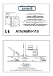
LEGENERATOR
210~
CONTENTS
Page
Section
1.
SPECIFICATIONS
2.
PERFORMANCE
2-1
CURVES ...............................................................
AC Output ..............................................................................
2-2 DC Output ..............................................................................
3. FEATURES ..................................................................................
4. GENERAL DESCRIPTION OF THE GENERATOR ..................................
4-1
1
..........................................................................
External View of Generator
2
2
3
4
5
...........................................................
5
4-2
Location of Serial Number and Specification Number ...............................
CONSTRUCTlON
AND FUNCTION
.....................................................
5.
5-1
Construction ...........................................................................
5-2
6
7
7
7
Function ................................................................................
6.
5-3
Description of Generator Operation ................................................
SAFETY PRECAUTIONS
................................................................
12
7.
RANGE
13
OF APPLICATIONS
8. MEASURING
............................................................
PROCEDURES
..........................................................
10
17
Measuring Instruments
...............................................................
8-2
AC Output Measuring
................................................................
17
20
8-3
DC Output Measuring
...............................................................
20
8-1
8-4
Measuring Insulation resistance .....................................................
FUNCTIONAL
MEMBERS
...............................................
9. CHECKING
Control panel.. ........................................................................
9-1
21
23
23
9-2
Stator ..................................................................................
24
9-3
Rotor ..................................................................................
25
9-4
Condenser
26
9-5
Diode
............................................................................
Rectifier
........................................................................
10. DISASSEMBLY AND ASSEMBLY ....................................................
10-1 Preparation and Precautions ........................................................
10-2
10-3
Disassembly Procedures .............................................................
Assembly procedures ................................................................
11. TROUBLE
SHOOTING
11-1
No AC Output.
11-2
AC voltage
12. WIRING
is too
DIAGRAM
..................................................................
.......................................................................
high
or too low
...................................................
......................................................................
26
2 7
27
28
38
44
44
46
47
S
E
R
\/I
Rk
C
E
RG-32
September-1995
NEWS
Generators
@ FUJIHEAVY
INDUSTRIES
LTD.
INDUSTRIAL PRODUCTS DIV.
I
MODEL
SUBJECT
I
R1210
Oil Sensorchange
This Service News is to inform of the change of the oil sensorand wiring equipped with
the ROBIN engine EY 15 for R1210 generator set.
1. Purpose
To improve the performance of the oil sensor.
2. Main points of the modification
1) The oil level sensing mechanism of the oil sensoris changedfrom piezo-resonator
type to potentiometer type.
2) The electric wiring and clamp are also changed.
3. Change of part number -
For the detail, refer to the attached figures.
New Parts set
NO.
1.
2.
3.
Part Name
Oil sensor CP.6
Wire 7 CP.
Clamp
Current parts set
NO. Part name
4.
5.
6.
Oil level sensor CP.
Wire 22 CP.
Clamp CP.
Part number
KS3-11015-01
227-73 107-O1
056-60002-50
+?k
Parl number
227-76035-01
214-73122-01
206-75501-01
Q’tv
1
1
1
1
1
Interchangeability
It is interchangeableonly when the all parts are replaced as a set; that is to say,
the current parts set (item NO.4 to 6) can be replaced with new parts set (item NO. 1
to 3). However, there is no interchangeability for the individual part.
4. Execution
This oil sensorchangeis adoptedto the new ROBIN generatorset to be produced in
and after September 1995.
-1-
I
Attachment (A); oil sensorinstallation change
New installation
*:Clamping in detail
Current installation
Attachment (B)
1. Oil sensorchange
New
Current
OIL SENSOR CP 6
KS3-11015-01
OIL LEVEL SENSOR CP
227-76035-01
-3-
2. Electric wiring change
New
wIRE7CP.
227-73107-01
Current
wm
22 cP .
214-73122-01
3. Clamp change
New
CLAMP
056-60002-50
d 6.5
Current
CLAMP CP.
206-75501-01
3I
\
+IA
J-c
\
I
I
A
-3
Section A-A
-4-
1. SPECIFICATIONS
Generator
Bushless, self-exciting,
revolving field
Type
Frequency
AC Voltage
(Rated current)
2-pole, single phase,
50 Hz
60 Hz
11 OV (7.3 A)
11OV (9.1 A)
220V (3.6 A)
12OV (8.3 A)
230V (3.5 A)
220V (4.5 A)
240V (3.3 A)
Max.
/
Rated
/
Engine
1000 w
1200 w
800 W
1000 w
AC Output
:
DC Output
12V-8.3A(lOOW)
Voltage regulation
system
Condenser system
Type
’
Forced air-cooled, 4-stroke, side valve,
gasoline engine
Displacement
,
143 cc (6.73 cu. in)
63 x 46 mm (2.48 x 1.81 in)
Bore x Stroke
I
Automotive gasoline
I
Fuel
!
Fuel tank capacity
3.5 liters (0.9 U.S. gal)
Oil pan capacity
600 cc (1.3 U.S. pints)
Rated continuous operating hours
Dimensions
(L X W X H)
;
486 x 288 x 410 mm
(19.1 x 11.3 X 16.1 in.)
27.5 kg (60.6 Ibs.)
Dry weight
-5-
2. PERFORMANCE
CURVES
2-1 AC OUTPUT
>^ 240
E
59 220
9
800
Frequency ........................
50Hz
...........................
220v
200
1,
I
I
$
F
t
i?
05
I
A
55
5
6
3
s
E
1(-J)()w
8OOW
Voltage
600
2
Output Max. ......................
Rated .....................
5
400
50
45
0
200
1
0
2
3
CURRENT(A)
4
5
Output Max. ......................
Rated ....................
Frequency ........................
Voltage ...........................
600
=g
i=
400
oI;i
1
200
2
3
CURRENT(A)
4
5
0
-2-
z
s
12o()w
,oooW
60~~
12ov
DC OUTPUT
m
voltage
.........................
DC Ampere
.........................
DC output
.........................
,2v
8.3A
,()ow
The voltage curve shown in the left indicates the
characteristic of DC output when charging a battery.
The voltage may be decreased by 20% when the
resistance load is applied.
I
0
2
4
CURRENT
6
(A) -
8
10
-3-
3. FEATURES
3-l
BRUSHLESS
ALTERNATOR
New brushless alternator has put an end to costly brush maintenance and down time.
3-2 CONDENSER
VOLTAGE
REGULATOR
Condenser voltage regulation ensures stable voltage output under all working conditions.
3-3 COMPACT, LIGHTWEIGHT,
CARRYING
EASE
As the new burshless alternator makes the Robin R1210 lightest in the class at 27.5 kgs, you can
easily carry it around using the convenient carrying handle.
34
EASY OPERATION
One-touch engine control switch integrates engine on/off switch and choke lever. All controls are
conveniently concentrated on the front panel.
3-5 LONG CONTINUOUS
OPERATION
The large 3.5 liters fuel tank allows four hours of operation at 50Hz rated output.
3-5 MINIMAL MAINTENANCE
Brushless alternator eliminates time consuming brush maintenance.
Trouble-free condenser voltage regulation for greater dependability.
No-fuse resettable circuit breakers.
0 Electronic pointless ignition system for sure starts.
l
l
l
3-7 LONG LIFE DURABILITY
Tough, heavy-duty Robin EY15 engine incorporates a cast iron cylinder liner, forged steel
crankshaft and two main ball bearings for longer service life.
0 The brushless alternator dose not have any expendable parts such as brushes and slip rings or
fragile circuit board assuring trouble-free operation for longer service life.
l
-4-
4. GENERAL DESCRIPTION OF THE GENERATOR
4-1 EXTERNAL VIEW of GENERATOR
Engine Control Switch
(CHOKE-RUN-STOP)
DC Circuit Breaker
AC Receptacle
Ground Terminal
Air Cleaner Cover
Carrying Handle
Spark Plug Cover
-
Fuel Tank
/
\-
Drain Plug
-5-
Oil Filler Cap
Fuel Tank Cap
4-2 LOCATION of SERIAL NUMBER and SPECIFICATION
NUMBER
Serial number and specification number are stamped on the LABEL(MODEL
cover.
NAME)stuck on the rear
NOTE: Always specify these numbers when inquiring about the generator or ordering spare parts in
order to get correct parts and accurate service.
LABEL (SPEC.)
/
/
LABEL (MODEL
[Example]
r
PROD. NO. RGOl2216010-*
1234 1000001 1
SER. NO.
L
4
L
Specification
Production
Serial No.
-6-
No.
No.
5. CONSTRUCTION AND FUNCTION
5-1 CONSTRUCTION
ROTOR COMPLETE
END COVER
tip Co”PLER
y-
REAR YOVER
,
STATOR
COMPLETE
\
\
,
i
’
DlODi
RECTIFIER
:
,
BALL BLARING
STATOR COVER
;
CONDiNSER
THROtiGH
MOUNT
&BBER
I
I
BOLT
FRONT ~&OVER
Fig. 5-7
5-2 FUNCTION
5-2-i
STATOR
The stator consists of a laminated silicon steel
sheet core, a main coil and a condenser coil which
are wound in the core slots.
The condenser coil excites the rotor field coil
which generates AC voltage in the main coil.
I
I
I
I
I
Fig. 5-2
-7-
5-2-2
CONDENSER
I
A condenser is mounted on the rear cover and is
connected to the condenser coil which is wound on
the stator. This condenser and condenser coil regulate the output voltage.
Fig. 5-3
5-2-3
ROTOR
The rotor consists of a laminated silicon steel
sheet core and field coil which is wound over the
core.
DC current in the field coil magnetizes the steel
sheet core. Two permanent magnets are provided
for the primary exciting action.
A cooling fan is pressure-fitted on the end of the
rotor shaft to cool the coils, cores, rectifier, and
other generator parts. (See Fig. 5-4)
Fig. 5-4
A diode rectifier and resister are mounted inside of
the insulator. (See Fig. 5-5)
Cooling air is sucked by the rotor fan through the
slits of the rear cover and is expelled through the
outlets of the front cover.
DE RECTIFIER
Fig. 5-5
-8-
5-2-4
CONTROL PANEL
The control panel has a double AC receptacle with
a ground terminal, and a DC receptacle.
The voltmeter displays output voltage of the generator. The circuit breaker for AC and DC in the
upper section of the control panel protects the
generator from getting damages caused by overloading or defective appliance.
I
Fig. 5-6
-9-
5-3 DESCRIPTION
of GENERATOR
OPERATION
INITIAL
EXCITATION
PERMANENT MAGNETO
FIELD
STATOR
COIL
ROTOR
7 ----_---It
RESISTOR or
/
r- ---
MAIN
DIODE
COIL
CONDENSER
COIL
Fig. 5-7
5-3-l
GENERATION
of NO-LOAD VOLTAGE
(1) When the generator starts running, the permanent magnet built-in to the rotor generates 3 to 6V of
AC voltage in the main coil and condenser coil wound on the stator.
(2) As one or two condensers are connected to the condenser coil, the small voltage at the condenser
coil generates a minute current @ which flows through the condenser coil. At this time, a small flux
is produced with which the magnetic force at the rotor’s magnetic pole is intensified. When this
magnetic force is intensified, the respective voltages in the main coil and condenser coil rise up.
As the current @ increases, the magnetic flux at the rotor’s magnetic pole increases further. Thus the
voltages at the main coil and condenser coil keep rising by repeating this process.
(3) As AC current flows through the condenser coil, the density of magnetic flux in the rotor changes.
This change of magnetic flux induces AC voltage in the field coil, and the diode rectifier in the field
coil circuit rectifies this AC voltage into DC. Thus a DC current %$flows through the field coil and
magnetizes the rotor core to generate an output voltage in the main coil.
(4) When generator speed reaches 2700 to 2800 rpm (50Hz type) or 3000 to 3300 rpm (60Hz type), the
current in the condenser coil and field coil increases rapidly.
This acts to stabilize the output voltage of each coils. If generator speed further increases to the rated
value, the generator output voltage will reach to the rated value.
5-3-2
VOLTAGE
FLUCTUATIONS
UNDER LOAD
When the output current g flows through the main coil to the appliance, a magnetic flus is produced and
serves to increase current 3 in the condenser coil. When current @ increases, the density of magnetic
flux across the rotor core rises. As a result, the current flowing in the field coil increases and the
generator output voltage is prevented from decreasing.
- 10-
5-3-3
DC OUTPUT
DC output is taken out from the DC coil and is fed
to the diode stack (rectifier) where the output
undergoes full-wave rectification and is then
supplied to the load. The diode works to allow the
current to flow in the direction 83, but does not
allow the current to flow in the direction 8, as
shown in Fig. 5-8-l.
Fig. 5-8-7
Fig. 5-8-2 shows the DC output circuit of the
generator. DC voltage is generated in the DC coil.
When the voltage in A is higher than that in 6, the
current @ flows in the direction shown in the
figure, while no current flows between CF and DE
because the current is cut off by the diodes G4 and
G2. On the contrary, when the voltage in B is
higher than that in A, the current (2 flows in the
direction as shown in the figure. No current flows
between CD and EF because the current is cut off
by the diodes Gl and G3.
A
x
B
Fig. 5-8-2
As a result, the voltage generated at the output
terminal has a wave form with two peaks in one
cycle, as in the case of the output wave form
shown in Fig. 5-B-3.
Output Waveform
Fig. 5-8-3
CAUTION : Do not use DC and AC output simultaneously.
Due to a characteristic
of the condenser voltage regulation, simultaneous use of DC
and AC output creates voltage drop in DC output resulting in incapability for charging
batteries.
- 11 -
6. SAFETY PRECAUTIONS
1. Use extreme caution near fuel. A constant danger of explosion or fire exists.
Do not fill the fuel tank while the engine is running. Do not smoke or use open flame near the fuel
tank. Be careful not to spill fuel when refueling. If spilt, wipe it and let dry before starting the engine.
2. Do not place inflammable
materials near the generator.
Be careful not to put fuel, matches, gunpowder, oily cloth, straw, and any other inflammables near the
generator.
3. Do not operate the generator in a room,cave or tunnel. Always operate in a well-ventilated
area.
Otherwise the engine may overheat and also, the poisonous carbon monoxide contained in the exhaust
gases will endanger human lives. Keep the generator at least 1 m (4 feet) away from structures or
facilities during use.
4. Operate the generator on a level surface.
If the generator is tilted or moved during use, there is a danger of fuel spillage and a chance that the
generator may tip over.
5. Do not operate with wet hands or in the rain.
Severe electric shock may occur. If the generator is wet by rain or snow, wipe it and thoroughly dry it
before starting.
Don’t pour water over the generator directly nor wash it with water.
If the generator is wet with water, the insulations will be adversely affected and may cause current
leakage and electric shock.
6. Do not connect the generator to the commercial power lines.
This may cause a short-circuit or damage to the generator.
Never connect the generator to the existing house wiring. If connected, the generator will burn out
when the commercial power source is recovered.
7. Don’t operate the generator with its cover removed.
The operator may be injured or suffer electric shock.
CAUTION;
If the circuit breaker tripped off as a result of using an electrical appliance, the cause
can be an overload or a short-circuit.
In such a case, stop operation immediately
and carefully check the electrical
appliance and plugs for faulty wiring.
- 12 -
7. RANGE OF APPLICATIONS
Generally, the power rating of an electrical appliance indicates the amount of work that can be done by it.
The electric power required for operating an electrical appliance is not always equal to the output wattage
of the appliance. The electrical appliances generally have a label showing their rated voltage, frequency,
and power consumption (input wattage). The power consumption of an electrical appliance is the power
necessary for using it. When using a generator for operating an electrical appliance,the power factor and
starting wattage must be taken into consideration.
In order to determine the right size generator, it is necessary to add the total wattage of all appliances to
be connected to the unit.
Refer to the followings to calculate the power consumption of each appliance or equipment by its type.
(1)
Incandescent
lamp, heater, etc. with a power factor of 1.0
Total power consumption must be equal to or less than the rated output of the generator.
Example:
A rated 1OOOWgenerator can turn ten 1OOWincandescent lamps on.
(2)
Fluorescent
lamps,mercury
lamps, etc. with a smaller power factor
Select a generator with a rated output equivalent to 1.2 to 2 times of the power consumption of the
load.
Example:
A 400W mercury lamp requires 600W to 700W power source to be turned on.
A rated 1OOOWgenerator can power one 400W mercury lamp.
NOTE I:
If a power factor correction capacitor is not applied to the mercury lamp or fluorescent
/amp, the more power shaN be required to drive those lamps.
A rated 1OOOW generator may unable to drive a 400W mercury lamp without power
factor correction capacitors.
NOTE 2: Nominal wattage of the fluorescent lamp generally indicates the output wattage of the
lamp.
Therefore, if the fluorescent lamp has no special indication as to the power consumption,
efficiency should be taken into account as explained in item (5) on the following page.
(3)
Motor driven tools and light electrical
appliances
Generally the starting wattage of motor driven tools and light electrical appliances are 1.2 to 3 times
lager than their running wattage.
Example:
A rated 250W electric drill requires a 400W generator to start it.
(4)
Initially
loaded motor driven
appliances
such as water pumps,compressors,etc.
These appliances require large starting wattage which is 3 to 5 times of running wattage.
Example:
A rated 9OOW compressor requires a 4500W generator to drive it.
NOTE 7: Motor-driven appliances require the aforementioned generator output only at the starting.
Once their motors are started. the appliances consume about 7.2 to 2 times their rated
power consumption so that the excess power generated by the generator can be used
for other electrical appliances.
NOTE 2: Motor-driven appliances mentioned in items (3) and (4) vary in their required motor
starting power depending on the kind of motor and start-up load. If it is difficult to
determine the optimum generator capacity, select a generator with a larger capacity.
- 13-
(5) Appliances
without
any indication
as to power consumption
Some appliances have no indication as to power consumption; but instead the work load (output) is
indicated. In such a case, power consumption is to be worked out according to the numerical formula
mentioned below.
(Output of electrical appliance) = (Power consumption)
(Efficiency)
Efficiencies of some electrical appliances are as follows:
Single-phase motor - a* . . e. - * . * * . . * . - 0.6 - 0.75
Three-phase motor * * a. - . * * * - * . . * * * 0.65 - 0.9 ItFluorescent lamp - * * . * * . * * * . * * . . - . * * 0.7 - 0.8
The smaller the motor, the
lower the efficiency.
Example 1: A 40W fluorescent lamp means that its luminous output is 40W. Its efficiency is 0.7 and
accordingly, power consumption will be 40 + 0.7= 57W. As explained in item(2), multiply
this power consumption value of 57W by 1.2 - 2 and you will get the figure of the necessary
capacity of a generator. In other words, a generator with a rated output of 1OOOWcapacity
can light nine to fourteen 40W fluorescent lamps.
Example 2: Generally speaking, a 400W motor means that its work load is 400W. Efficiency of this
motor is 0.7 and power consumption will be 400 + 0.7= 57OW. When this motor is used for
a motor-driven tool, the capacity of the generator should be multiplied by 1.2 to 3 and 570W
as explained in the item(3).
Applicable
Electrical
50Hz
60Hz
lncandesent
lamp, heater, etc.
approx.800W
Fluorescent
lamp, mercury lamp, etc.
approx. SOW
Motor-driven
tool, general-purpose
Water pump, compressor,
limit
appliance
motor, etc.
etc.
I
I
approx. 500W
approx. 250W
approx.1 OOOW
approx. 650W
approx. 600W
’
approx. 300W
Table 7-1
NOTES:
Wiring between generator and electrical appliances
1. Allowable current of cab/e
Use a cable with an allowable current that is larger than the rated input current of the load
(electrical appliance). If the input current is larger than the allowable current of the cable used, the
cable will become excessively heated and deteriorate the insulation, possibly burning it out.
Table 7-2 shows cables and their allowable currents for your reference.
2. Cable length
If a long cab/e is used, a voltage drop occurs due to the increased resistance in the conductors
decreasing the input voltage to the load (electrical appliance). As a result, the load can be
damaged.
Table 7-2 shows voltage drops per 100 meters of cab/e.
-
14-
’ Nominal cross
sectlon
/ Redstance
I
Current Amp.
Table 7-2
Voltage drop indicates as V = &XRxIxt?
R means resistance ( 9 /lOO m) on the above table.
I means electric current through the wire (A).
Q means the length of the wire (m).
The length of wire indicates round length, it means twice the length from generator to electrical tools.
7-1 DC OUTPUT
NOTE : Do not use DC and AC output simultaneously.
Due to a characteristic of the condenser voltage regulation, simultaneous use of DC and AC
output creates voltage drop in DC output resulting in incapability for charging batteries.
When the generator is employed to charge batteries, attentions should be paid to the specific gravity of
electrolyte in the battery.
7-2-l
SPECIFIC GRAVITY OF BATTERY ELECTROLYTE
The specific gravity of electrolyte varies by temperature ; so it must be converted to the one at 20°C.
s20 = St + 0.0007 (t-20)
where
S20 : The specific gravity at 20°C
St : Measured value
t
: Temperature at the time of measurement (Electrolyte)
- 15 -
7-2-2
SPECIFIC GRAVITY OF BATTERY ELECTROLYTE
Speclflc
gravity
(20%)
Charging
condintion
1,260
100
1,240
87
1,220
75
1,200
62
1,180
50
1,160
37
1,140
25
AND CHARGING CONDITION
Remarks
Charging is not necessary.
Charging is necessary.
Immediate Charging is necessary.
Table 7-3
7-2-3
BAlTERY
CAPACITY
The battery capacity is expressed in the unit of AH (ampere-hour). One AH stands for the capacity
capable of one ampere current for one hour.
-16-
8. MEASURING
8-1 MEASURING
PROCEDURES
INSTRUMENTS
8-l -1 “Dr. ROBIN” GENERATOR
TESTER
The “Dr. Robin”generator tester is exclusively
designed for fast, easy diagnosis and repair of
Robin generators.
The “Dr. Robin” has the following features:
(1) Functions of voltmeter, frequency meter,
megger tester, capacitance meter and circuit
tester are combined in one unit.
(2) Fast and easy readout by digital indicator.
(3) Built-in automatic battery checker indicates
the time to change batteries.
(4) Tester and accessories are installed in a
handy, sturdy case for easy carrying.
l
Fig.8-1
SPECIFICATIONS
Dr. Robin
Model
Part Number
388-47565-08
Voltage
i!l
2 : Frequency
0-500V AC
P
‘C
2
9
2
0.1-l ,999 0
25-70Hz
Resistance
Condenser
Capacity
lo-100
Insulation Resistance
,YF
3MQ
Fuse
Circuit Protector
2 x 6F44P (006P) Dry Cell Battery
Power Source
Test leads with needle probes . . . 1 set
Accessories
Test leads with jack plugs . . . . . . 1 set
Dimensions
(L X W X H)
285 mmx200
Weight
mmxll0
mm
1.6kg
Table 8-l
The “Dr. Robin”generator tester can be ordered from Robin generator distributors by the following part
number.
Dr. Robin Part Number : 388-47565-08
If you do not have a “Dr. Robin’generator tester,use the instruments described in the following section
for checking generator parts.
-
17-
8-l-2
I
INSTRUMENTS
(1) VOLTMETER
AC voltmeter is necessary. The approximate
AC voltage ranges of the voltmeters to be
used for various types of generators are as
follows:
0 to 150V: Type with an output voltage of
110 or 12OV
0 to 300V: Type with an output voltage of
220,230 or 240V
0 to 15OV, 0 to 330V: Dual voltage type
i
’
For AC
Fig. 8-2
-
(2) AMMETERS
AC ammeter is necessary. An AC ammeter
with a range that can be changed according to
the current rating of a given generator is most
desirable. (About lOA, 20A, 1OOA)
For AC
Fig. 8-3
(3) FREQUENCY METER
Frequency range : About 45 to 65Hz
NOTE: Be careful of the frequency meter’s
input voltage range.
Fig. 8-4
-
18-
1
(4) CIRCUIT TESTER
This circuit tester is used for measuring resistance, etc.
I
!
Fig. 8-5
(5) MEGGER TESTER
Used for measuring generator insulation resistance.
Select one with testing voltage range of
5oov.
I
1
Fig, 8-6
(6) TACHOMETER
Use the contact-less type tachometer.
Fig. 8-7
- 19 -
8-2 AC OUTPUT MEASURING
To AC
Fig. 8-8
Measurement is executed with the circuit as shown in Fig. 8-8. An electric heater or an incandescent
lamp with a power factor of 1.0 is suitable as a load for the generator. When the AC output measured at
the rated load and rated speed is confirmed to be within the voltage range specified in the table below,
the AC output is normal.
Rated voltage
Voltage range
1lOV
1
107-119v
i
120v
!
220v
240V
117-130V
(
215-236V
235-260V
Table 8-2
8-3 DC OUTPUT MEASURING
Load
4
To AC Receptacle
1
Fig. 8-9
Measurement of DC output is executed with the swirch turned OK while the current is regulated at 8.3A
by adjusting the load to the generator. If the voltage is within the range from 1OV to 14V, the voltage
output is normal.
Note : If a battery is connected as a load to the generator, the DC output voltage will increase by
approximately I to 2V. Therefore, carefully observe the electrolyte level and do not overcharge
the battery.
- 20 -
84
MEASURING
INSULATION
RESISTANCE
Use a “Dr. Robin”generator tester in megger tester
mode or use a megger tester to check the insulation resistance. Connect a megger tester to one
of receptacle output terminals and the ground terminal, then measure the insulation resistance. An
insulation resistance of 1 megohm or more is
normal. (The original insulation resistance at the
time of shipment from the factory is 10 megohm
or more.)
If it is less than 1 megohm, disassemble the
generator and measure the insulation resistance of
the stator, rotor and control panel individually.
;
I
Fig. 8-10
l
STATOR
(1) Measure the insulation resistance between
BROWN lead and the core.
(2) Measure the insulation resistance between
YELLOW lead and the core.
(3) Measure the insulation resistance between
BLACK lead and the core.
Fig. 8-i 1
l
ROTOR
Measure the insulation across one of the soldered
terminals of the rotor and the core.
Fig. 8-12
-
21 -
l
CONTROL PANEL
Measure the insulation resistances between the
live parts and the grounded parts.
Fig. 8-13
Any part where the insulation resistance is less than 1MQ has faulty insulation, and may cause electric
leakage and electric shock.
Replace the faulty part-
-
22 -
9. CHECKING FUNCTIONAL
9-l
MEMBERS
CONTROL PANEL
9-1-1
AC RECEPTACLES
Using a “Dr. Robin”or a circuit tester, check continuity between the two terminals at the rear of the AC
receptacles while the receptacle is mounted on the control panel. When continuity is found between the
output terminals of the receptacle with a wire connected across these terminals, the AC receptacle is
normal. When the wire is removed and no continuity is found between these terminals, the receptacles
are also normal.
WIRE
Fig. 9-16
Fig. 9- 1A
9-l-2
DC RECEPTACLE
Check continuity between the DC terminals at the
rear of the receptacle using a circuit tester, under
the condition that the receptacle is mounted on the
control panel.
When continuity between the DC terminals of the
receptacle is confirmed with a wire connected
across the terminals, and is not confirmed if the
wire is removed, the DC receptacle is normal.
Fig. 9-2
9-l-3
CIRCUIT BREAKER
Check continuity between the two terminals at the
rear side of the circuit breaker using a circuit tester
while it is mounted on the control panel.
If continuity is confirmed when the breaker is ON,
and no continuity is confirmed when the breaker is
OFF, the circuit breaker is normal.
Fig. 9-3
- 23 -
9-l-4
VOLTMETER
Check the voltmeter if it operates correctly by
applying specified voltage. Voltmeters cannot be
checked with a circuit tester because its internal
resistance is too large.
Voltmeter
Fig. 9-4
9-2 STATOR
COUPLER
Disengage connectors on the wires from stator and
check the resistance between wires with a “Dr.
Robin” or a circuit tester referring to the following
table.
-
k
Fig. 9-5
(Rx1 Q +10”/,)
Specification
AC Winding
DC Winding
I
Brown /White
Yellow / Red
11ov
I
1.7 0
220v
#
6.3 Q
220V O/DE spec.)
i
7.3 0
1.0 0
240V
8.1 Q
0.84 Q
11ov
1.0 0
Voltage
Hz
50
60
1
!
,
i
12ov
1.3 0
220v
4.0 Q
240V
I
Condenser
Winging
Black / Black
0.84 0
4.9 0
0.56 0
4.2 Q
I
5.0 n
Table 9- 1
NOTE:
If the circuit tester is not sufficiently accuratejt may not show the values given and may give
erroneous readings.
Erroneous reading will also occur when there is a wide variation of resistance among coil
windings or when measurement is performed at ambient temperatures different from 2O”C(68”F).
- 24 -
9-3 ROTOR
1) Using the “Dr. Robin”or a circuit tester, measure the resistance of the field coil.
(See Fig. 9-6.)
(RxlQ+lo%)
I
Resistance
I
I
8.5 Q
I
NOTE 7: Because a diode is soldered to the coil
ends at the terminals, resistance may
be measured on/y when tester probes
touch the terminals in one combination
of polarity. Therefore, if no resistance
reading appears, try checking in reverse polarity.
NOTE 2:
;
i
i
If the circuit tester is not sufficiently
accurate, it may not show the values
given
and
may
give
erroneous
readings.
Erroneous reading will also occur when
there is a wide variation of resistance
among coil windings or when measurement is performed at ambient tempera tures different from 20°C(68”F).
Fig. 9-6
2) Measure the resistance of the resister.
I
Normal resistance
I
3) Measure the resistance of the diode.
POLARITY OF
CIRCUIT TESTER
CATHODE MARK
I
[Continuity exists]
I
Fig. 9-7
- 25 -
[“Ql
9-4 CONDENSER
H Use a “Dr. Robin” in capacitance meter mode to check the capacity of condensers. (See Fig. 9-8.)
NOTE:
Be sure to discharge condensers by
shorting condenser leads each other before checking their capacitance,or
the
accurate reading cannot be obtained.
L
Fig. 9-8
n
If such an instrument is unavailable, the condenser can be checked by replacing with a new one.
If the generator performs good with new condenser, the cause of trouble is defect in original
condenser.
9-5 DIODE RECTIFIER
Red
Green
Red
Green
Green
Fig. 9-9
DIODE RECTIFIER
CIRCUIT TESTE
Fig. 9-10
The internal circuit of the diode rectifier is as shown in Fig. 9-9.
Check continuity between each terminal using a circuit tester as shown in Fig. 9-10.
- 26 -
Green
w Checking table for analogue circuit tester.
Apply black 0 needle of the circuit
Analogue
circuit
tester
tester
Green
Green
Green
Apply red @ needle
of the circuit tester
Red
No continuity
Green
Red
Table 9-2- 1
n
Checking table for digital circuit tester.
Apply
Digital circuit
red @needle
of the circuit
tester
tester
Green
Green
Red
Green
Apply black @ needle
of the circuit tester
Green
Red
Table 9-2-2
NOTE I:
Because of the difference of measuring method between the analogue circuit tester and the
digital circuit tester, polarity of tester needles should be reversed.
NOTE 2:
“Continuity” means forward direction characteristics of the diode, and different from short
circuit condition (in which a pointer of the tester goes out of its normal scale), shows
resistance to some extent. When result of the checking indicates failure even in one
section,replace with a new one.
NOTE 3:
“Simpson” brand analogue testers have the characteristic as same as the digital circuit tester.
10. DISASSEMBLY AND ASSEMBLY
1O-l PREPARATION
and PRECAUTIONS
1) Be sure to memorize the locarion of individual parts when disassembling the generator so that the
generator can be reassembled correctly. Tag the disassembled part with the necessary information to
facilitate easier and smoother reassembling.
2) For more convenience, divide the parts into several groups and store them in boxes.
3) To prevent bolts and nuts from being misplaced or installed incorrectly, place them temporarily back
at their original position.
4) Handle disassembled parts with care; clean them before reassembly using a neutral cleaning fluid.
5) Use all disassembly, assembly tools properly, and use the proper tool for each specific job.
- 27 -
10-2 DISASSEMBLY
PROCEDURES
Remarks
Description
Tool
tep
Part to remove
1.
Side cover
(1) Remove the side cover by unscre\xing
four M5 X 8 screws. (SeeFig. 10-l.)
(+) Plus screw
driver
2.
Rearcover
(1) Remove the rear cover by unscrewing
three M5 X 8 screws and two M8 X 10 ’
screws.(SeeFig. 10-2.)
(+) Plus driver
Fig. lo-2
-
3.
Control panel
(1) Pull the knob off the control lever and
removethe control panel by unscrewing
four M.5 X 8 screws.(SeeFig. 10-3.)
(+) Plus driver
. .
Fig. IO-3
- 28 -
_,,,
I‘art to remove 1
step
4.
Couplers
and plugs
t (Disconnection)
Description
Remarks
I
(1) Disengage the couplers of stator wires
from the wires of control panel.
6P couplers(Yellow, Red, Green:
Yellow, Brown, White)
(SeeFig. 10-4.)
I
Pull the couplers while
pushingthe locking
hook.
(2) Disengagethe connector of grounding
wire.
Pin terminal (GreenA’ellow)
(SeeFig. 10-T)
I
Fig. 10-4
Fig. 10-5
Press the hook of the coupler
pull out to disconnect.
CONTROL
and
’
PANEL SIDE
STATOR SIDE
Fig. IO-6
I
I
- 29 -
Tool
5.
Front cover
(1) Removethe elementcover by
unscrew.-ing
M6 X 12 scre\v.
(SeeFig. 10-7.)
(-) Driver
(2) Remove the front cover by unscrewing
three $15 X 8 screws.(SeeFig. 10-S.)
(+) Driver
Fig. 10-8
Fig. 10-7
6.
Fuel pipe
and plug
(Disconnection)
Tool
Remarks
Descrlptlon
Step Part to remove
Use utmost care about
(1) Dischargefuel from the tank.
I fire hazard.
1. Shut the fuel striner.
2. Removethe strainercup.
3. Put a vessel to receive fuel under the i Wipe off spilt fuel
throughly.
strainer and open the fuel cock to
dischargefuel. (SeeFig. 10-9.)
4. Attach the strainer cup to the strainer Do not losethe filler
screen.
body
/ Pliers
(2) Disconnectfuel hosefrom the strainer.
Loosen the hose clamp on top of the
strainer and pull out the fuel hose from
the strainer.(SeeFig. 10-10.)
Fig. lo-10
Fig. 10-9
- 30 -
!Step I‘art
7.
to remove
Fuel tank
handle
I
Descrlptlon
(1) Removethe handlecover by unscrewing
the hvo I43 X 10 screws.
Remarks
The fuel tank can be
removedwithout
disassemblingthe
handle.
(2) Pull off the breatherpipe.
(3) Remove the handle body by taking off
the hv0 M8 nuts.
Tool
(+) Driver
13mm box wrench
Handle cover
\
Breather pipe
M3x IO Screw (2 PCS.)
A
Handle
Full tank
M8xNut
(2 pm.)
Fig. 10-11
- 31 -
I
Descrlptlon
I Step I Part to remove
8.
I
Fuel tank
I
’
Tool
Remarks
(1) Remove the two M6X 12 flange bolts
from the blower housing.
(SeeFig. 10-12.)
(2) Remove the fuel tank by taking off the
hv0 M8 nuts from the bottom of the
tank. (SeeFig. 10-13.)
Fig. 10-72
1Ommbox wrench
13mmbox wrench
I
Fig. 70-13
Bracket
(Cover)
(1) Remove the bracket cover from the
generatorby looseningthe two M8 X 30
bolts. (SeeFig. 10-14.)
13mmbox wrench
End cover
(1) Remove the end cover from the
generatorby unscrewingthe three%I X
8 screws.(SeeFig. 10-14.)
(+) Driver
Fig. lo-14
- 32 -
Step
Dart to remove
11.
Rear bracket
Description
Remarks
Tool
(1) Loosen and take out the three M6
bracketbolts. (SeeFig. 10-15.)
1Ommbox wrench
(2) Removecondenserfrom rear bracket.
Box spanner
(3) Remove the connector of the diode
rectifier and then removethe earth cable
terminal from the rear bracket.
(SeeFig. 10-16.)
Box spanner ant
screw driver (+)
Bracketbolt (3 PCS.)
Fig. 70-16
Fig. IO-15
(4) Remove the rear bracket, tapping it
evenly with a plastic mallet.
(SeeFig. 10-U.)
Plastic mallet
(5) Removemount rubbersfrom rear cover.
(SeeFig. 10-18.)
Wrench
mallet
Fig. 10-18
Fig. IO-17
- 33 -
Step
12.
Part to remove
Stator
Descrlptlon
Remarks
Tool
(1) Remove the stator cover.
(SeeFig. 10-19.)
(2) Pull off the stator from the front cover
tapping the core with a plastic mallet.
(SeeFig. 10-20.)
Fig. 10-79
Never tap on the
winding andthe lead.
Fig. IO-20
Fig. 70-22
Plasticmallet
Step I ‘art to remove
13.
Descrlptlon
Rotor
Remarks
(1) Take off the through bolt.
Apply a box wrench on the head of
throughbolt. Hit the wrench handlewith
a hammercounter-clockwiseto loosen.
Box wrench
Plastichammer
i
Fig. 10-23
!
t-
(2) Put the engine on the working table
recoil slarterside down.
t
(3) Use a bolt and oil as a rool for pulling
out rotor in the follo\ving procedures:
1. Pour engineoil into the centerhole of
rotor shaft.
Fill with oil to the shaft end.
(SeeFig. 10-24.)
2. Prepare a bolt with the following
threadsize : M8 X P 1.25
3. Apply a few turns of seal tape around
the tip of the bolt.
(SeeFig. 10-25.)
i
I
!
I
Fig. 1O-25
Fig. 70-24
- 35 -
Tool
Step
13.
tart to remove
Rotor
-I-
Remarks
Description
4. Screw the bolt into the thread of the
rotor shaft.
5. Torque the bolt using a socket wrench
until the rotor comesoff loose.
* The hydraulic pressureinside the rotor
shaft takes apart the rotor from the
engineshaft.
Socketwrench
(4) Wipe off oil throughly from rotor shaft
andenginePTO shaft.
Fig. 10-26
Front bracket
(1) Remove the front bracket. which is
mounted on the main bearing cover of
the engine, by taking out four M8 X 18
bolts. (SeeFig. 10-27.)
Fig. 10-27
- 36 -
! 13 mmbox spanner
itep
‘art to remove
15.
Mount
rubbers
Remarks
Description
12 mm wrench
(1) Removemountbracketfrom engine.
Remove mount rubbers from mount
bracket.
8 @INut : 3pcs.or Zpcs.
Mount bracket
Mount rubber
Fig. 10-28
- 37 -
Tool
\
10-3 ASSEMBLY
10-3-l
PROCEDURES
FRONT BRACKET
Install the front bracket on the main bearing cover
of the engine, engaging the faucet joint.
(See Fig. 10-29.)
M8 X 20mm bolt and washer ass’y .*-*.... 4pcs.
Fig. 70-29
10-3-2
ROTOR
1) Wipe off oil from the tapered portion of engine shaft and matching tapered hole of rotor shaft.
(See Figs. lo-30 and 10-31.)
Fig. 10-31
Fig. lo-30
2) Install rotor on the engine shaft and tighten the
through-bolt.
Apply a wrench on the head of through bolt
and hit wrench handle clockwise with a hammer to tighten. (See Fig. 10-32.)
If an impact wrench is available, use it.
I
i
;
I
I
I
Fig. 10-32
- 38 -
10-3-3
STATOR
(1) Holding the rear bracket and stator, fit them
to the front bracket. Match the mounting hole
of the rear bracket and that of the rotor bearing, and softly strike the outside periphery of
the rear bracket with a plastic hammer. (See
Fig. 10-33.)
(2) Attach the stator cover around the stator.
Fig. lo-33
(3)
Tighten the three M6 bolts to fix the rear bracket to the front bracket .
TIGHTENING
TORQUE
(Rear bracket)
55 535 4.0 -
(4)
75 kg-cm
735 N *cm
5.4 ft Ibs.
l
Put the grommet in the groove of the rear bracket and secure the wire.
Note : Fix the wire from the stator and diode stack with the clamp at the bottom of the groove.
10-3-4
CONDENSER
Put condenser to rear cover.
5 o X 10 mm tapping screw ...*..*-....*.-
2 PCS.
Condenser
S
Fig. 1O-34
- 39 -
10-3-S
END COVER
Set the end cover on the rear bracket with three
M4 X 8 screws.
10-3-6
BRACKET
(COVER)
Mount the bracket (cover) on the rear bracket and
secure them with M8 X 30 bolts.
1
End cover
AlIza
I
\
i!
lCd/
Fig. 10-35
10-3-7
FUEL TANK AND FUEL PIPE (CONNECTION)
(1) Connect the rubber pipe to the engine carburetor and fasten it with a hose clamp, Attach the banjo to
the opposite end of the rubber pipe, tighten it with a hose clamp, and fasten the pipe to the fuel
strainer with the banjo bolt.
Note : Mount the fuel strainer with the banjo outlet upward.
(2) Fasten the strainer to the front bracket with the joint nuts.
(3) Secure the mounting tab on the bottom of the fuel tank and the blower housing with M6 X 12 bolts.
Insert the attaching bolts on the other end of tank into the mount bracket hole and secure it with two
M8 nuts.
(4) Connect the rubber pipe
First, fit the hose clamp on the rubber pipe, connect the strainer and fuel tank, then fasten the rubber
pipe with the hose clamps.
Note : Apply a drop of oil to the rubber pipe so that it may easi/y be connected to the strainer and the
fuel tank.
10-3-8
FUEL TANK HANDLE
(1) Match the handle hole with the bolt on the top of the fuel tank and secure it with M8 nuts.
(2) Completely insert the breather pipe over the bolt.
Note : There is a hole at the center of the breather pipe for air bleeding. Set the breather pipe so that the
hole is directed upward.
(3) Fix both ends of the handle cover with M3 X 10 screws.
- 40 -
nanale cover
M3X 10 Screw (2pc.s.)
to Carburetor
f
M8 Nut (2Gcs.) ; fy/-
k
Rubber hose,
Hose clamp
-
Fuel tank cap
\Ai
Fuel filter
Fuel strainer
Cup
M8 Nut (2 PCS.)
Rubder hose
Fig. lo-36
10-3-9
FRONT COVER AND ELEMENT COVER
(1) Secure the front cover, on which fuel strainer have been mounted, with three M5 X 8 screws.
(See Fig. 10-37.)
(2) Secure the element cover with M6 X 12 screws. (See Fig. 10-38.)
Fig. lo-38
Fig. lo-37
- 41 -
10-3-10
CONNECTION
OF WIRES
(1) Connect the wires drawn out from the stator to the wires from the control box. (See Fig. 10-39.)
(2) Press the couplers until the locking hook engages securely.
(3) Connect the grounding wire. (See Fig. 10-40.)
Fig. 1O-40
Fig. lo-39
WIRE CONNECTIONS
BETWEEN CONTROL PANEL AND STATOR]
Wire color : Yellow, Red, Green/Yellow, Brown, White
6P coupler
Green/Yell
Brown
Yellow
Red
White
STATOR SIDE
CONTROL PANEL SIDE
0 Earth (Ground) wire : Pin terminal
10-3-11
Wire color
Green/Yellow
CONTROL PANEL
(1) Put the control panel over the control lever
and secure it with four M5 screws.
(2) Attach the knob to the control lever.
Note :After the couplers and connectors have
been connected and secured to the control
panel, secure the wires with a wire band to
the control panel.
Fig. IO-41
-
42 -
10-3-12
r
II
REAR COVER
Secure the reaT cover with three M5X8 screws and
two M8 X 10 screws.
!
I
--
Fig. lo-42
10-3-13
I
SIDE COVER
Secure the side cover with four M5X 8 screws.
IIr’
I
Fig. IO-43
- 43 -
L-----r
:.
I
11. TROUBLESHOOTING
II-I
NO AC OUTPUT
II-I -1 CHECKING STATOR
n
n
Remove control panel and disconnect couplers on wiring.
Measure the resistance between terminals on
stator leads.
Refer to Table 9-l on page 24 for normal
resistance.
I
IRemedy
I
If stator is defective, replace with new one.
I
Fig. 17-1
11-I-2
CHECKING
CONDENSER
n
If an instrument (Q.C.-meter or C-meter) for measuring capacity of condenser is available, check the
capacity of condenser.
n
NORMAL
n
If you do not have such an instrument, you can check condenser by replacing with new one and test
running.
If the generator perform normally with new condenser, the cause of trouble is defect in original
condenser.
1 l-l-3
n
CAPACITY
CHECKING
OF CONDENSER
I
ROTOR
I
Remove rear cover and stator.
I
DIODE RECTIFIER
and RESISTOR
Fig. 7 l-2
-
44 -
!
n
Measure the resistance of field coil with a
circuit tester. (See Fig. 11-3.)
n
NORMAL
RESISTANCE
(RXlQ+-10%)
RESISTANCE
8.5 R
IRemedy
H If the resistance is not normal, replace rotor
with new one.
I
Fig. 1 l-3
H Unsolder and take out the diodes and the resistors.
w Measure the resistance of 2 pieces of diode.
P0LARll-Y OF
CIRCUIT TESTER
CATHODE MARK
[Continuity exists]
n
Measure the resistance of each resistor.
NORMAL
n
RESISTANCE
Check the magnetic force of magnets molded in the rotor.
[Remedy1
1. If the magnetic force is weak, replace the rotor with a new one.
2. If the diode or the resistor is faulty, replace them with new one. When all these parts are good,
assemble them and then solder.
-
45 -
(Reassembling]
1. Place the resistors at the bottom.
2. On the resistors put the diodes, taking care of
its polarity.
3. Solder them to the terminal.
*Resistor has no polarity.
(CROSS SECTION)
SOLDERING
RlklSTOR
(1 pee.)
Fig. II-4
11-2 AC VOLTAGE
11-2-1
IS TOO HIGH OR TOO LOW
CHECKING ENGINE rpm .
If the engine rpm is too high or too low, adjust it to the rated rpm .
mow to adjust engine rpm .]
n Loosen the nut on the adjusting screw.
n Turn the adjusting screw clockwise to decrease engine speed or counter-clockwise to
increase engine speed.
Normal engine speed at no load is :
3150 - 3200 rpm for 50 Hz type
3750 - 3800 rpm for 60 Hz type
1 l-2-2 CHECKING STATOR
Fig. 1 l-5
Check stator referring to Step 11-1-1.
1 l-2-3 CHECKING CONDENSER
Check condenser referring to Step 11-1-2.
11-2-4 CHECKING ROTOR
Check rotor referring to Step 11-1-3.
- 46 -
AC CIRCUIT
MAIN COIL
FIELD COIL
BREAKER
AC RECEPTACLE
SPARK
PLUG
I
RESISTOR
\
DIODE,
$‘J+=-
1
I
/
I
, whltn
V
/
/
- IGNITION
COIL
I
DC COIL
I
I
t
-‘MAGNETO
CONDENSER
COIL
1
I
/
2P COUPLER
I
i
CONDENSER
I
DIODE STACK ASSY
(RECTIFIRE)
DC RECEPTACLE
DC dlRCUlT
BREAKER
GROUND
TERMINAL
\
STOP SWITCH
a
FUJI
HEAVY
INDUSTRIES
LTD.