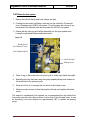
1
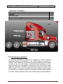
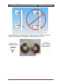
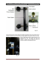
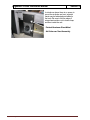
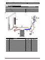
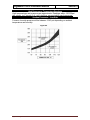
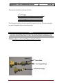
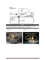
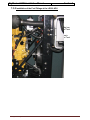
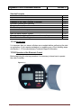
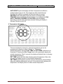
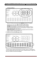
Installation Manual MTS-T4-LG200 RigMaster LG200 Installation Manual Table of Contents Safety Safety Information Preface Section 1 Introduction to Installation Introduction to Installation Definitions Necessary Tools Technical Assistance Placement of the LG200 Components 1:1:0 1:1:1 1:1:2 1:1:3 1:2:0 Section 2 Preparation and Frame Rail Mounting Preparing the LG200 Frame Mounting Hardware Frame Rail Mounting 2:1:0 2:2:0 2:2:1 Section 3 Installing the Bunk AC Unit Preparation to Install the AC Unit Mounting the AC Unit Ducting the Ventilation System Independent Ducting Vent Installation Installation of Return Air Vent Integrated Ducting 3:1:0 3:1:1 3:2:0 3:2:1 3:2:2 3:2:3 3:3:0 Section 4 Mounting the Control Panel Mounting the Control Panel 4:1:0 Section 5 Installing the Coolant Hoses Installation of the Coolant Fittings Installation of the Coolant Hoses 5:1:0 5:2:0 Section 6 Installing the A/C Hoses Installation of the A/C Refrigerant Hoses Installing the A/C Hoses in the engine compartment Installing the A/C hoses from the LG200 to the AC unit Air Conditioning Specifications 6:1:0 6:1:1 6:1:2 6:1:3 Section 7 Installing the Fuel System Installation of the Fuel System Installation of the Fuel Fittings at the Fuel Tanks Optional Fuel Pick Up Tube (Stand Pipe) Installation of the Fuel Fittings at the LG200 APU Prime the Fuel System August 2010 RigMaster Power International Ltd LG200 Service Manual 7:1:0 7:2:0 7:2:1 7:3:0 7:4:0 RigMaster LG200 Installation Manual Table of Contents Section 8 Exhaust System Ultra Quiet Exhaust System Diesel Particulate Filter Installation 8:1:0 8:2:0 Section 9 Electrical Connections Introductions to LG200 Electrical Connections Connecting the Engine Harness to the Power Module Evaporator Temperature Switch Wiring Connections Connecting the Cabin Controller DPF Backpressure Monitor Wire 9:1:0 9:2:0 9:3:0 9:5:0 9:6:0 Section 10 Installing the Battery Cables Introduction to Installing the Battery Cables Installing the Battery Cables to the LG200 Battery Posts Installing the 100 Amp Battery Fuse Installing the Battery Cables to the Vehicles Battery Bank 10:1:0 10:2:0 10:3:0 10:4:0 Section 11 Start-Up Procedure Introduction to Start Up Procedures Operation of the Electronic Control Cabin Controller LCD Display Operation of the Cabin Controller (Functions) AutoStart Features and Operation Electronic Control Operation and Fault Codes Pre-Start Inspection Test the Air Conditioning System Test the Alternator Complete the Installation Check List and Warranty Registration Diesel Particulate Filter Registration 11:1:0 11:2:0 11:2:1 11:2:2 11:2:3 11:2:4 11:3:0 11:4:0 11:5:0 11:6:1 11:6:2 Section 12 Installation Equipment List Installation Material List Installation Tools List Shop Equipment List August 2010 RigMaster Power International Ltd LG200 Service Manual 12:1:0 12:2:0 12:3:0 RigMaster LG200 Installation Manual Safety 1. Zero Energy State ATTENTION: ZERO ENERGY STATE To perform service, maintenance and repairs you must disconnect the LG200 from its battery source. In the recommended installation configuration the LG200 shares the battery bank with the vehicles main engine. Unplug the J1 harness at the power module before disconnecting the battery cables. After disconnecting the battery cables, check the battery posts inside the LG200 engine cabinet to confirm there is no voltage to the auxiliary power unit (APU). 2. Safety Cover Switch ATTENTION: SAFETY COVER SWITCH It is critical that this safety cover switch is never deactivated or bypassed. Failure to comply may result in serious injury. The safety cover switch is designed to prevent the LG200 from starting when the engine cover is loose or has been removed. When the switch is in the closed position the cover is down. When the switch is in the open position the cover has been removed or is loose. The switch is located at the very top of the unit enclosure on the coolant tank mounting bracket. Cover Safety Switch 3. AutoStart Automatic Start/Stop Feature ATTENTION: AUTOSTART FEATURE Remember that a properly functioning LG200 is capable of starting independently of its operator. If the AutoStart feature is enabled, battery voltage, temperature and time of day can all cause the LG200’s engine to start. Please see the cabin controller’s operating instructions for further information on the AutoStart feature. You must deactivate this feature prior to refueling. August 2010 RigMaster Power International Ltd LG200 Service Manual RigMaster LG200 Installation Manual 4. Safety Engine Hoist Points ATTENTION: ENGINE HOIST POINTS The Perkins and Caterpillar engines have hoist points that are useful for removal and reinstallation of the engine. It is advised that these hoist points should only be used if no other means of lifting the unit are available. 5. Starting Aids WARNING Do not use any type of starting aids such as ether or “Quick Start”. Using any such starting aid will result in an explosion, personal injury and severe damage to the engine. The APU warranty will be “voided” by this action. 6. Starting with the Cover Off ATTENTION Some installation or repair/diagnostic procedures require that the APU is started with the engine cover off. Never bypass the safety cover switch. Instead, have another individual assist by manually holding the safety cover switch down in the closed position for the duration of the procedure. 7. Inspection of the Safety Systems The safety systems on the LG200 should be examined and tested prior to performing any service work and at 50 hour intervals to ensure that they are in good condition and proper working order. 8. Safe Working Practices Safe working practices are your responsibility. The use of protective safety equipment is mandatory when performing inspections, service, diagnostics and repairs on the LG200. Follow your local regulations and guidelines regarding occupational health and safety. 9. Contact Us If you do not fully understand this safety information, contact RigMaster’s Technical Support Department toll free at (888) 208 – 3101 before proceeding with the operation or service of this APU. August 2010 RigMaster Power International Ltd LG200 Service Manual RigMaster LG200 Installation Manual Introduction to Installation Introduction to Installation Definitions Necessary Tools Technical Assistance Placement of the LG200 Components Section 1 1:1:0 1:1:1 1:1:2 1:1:3 1:2:0 Fig. 1-1 1:1:0 Introduction to Installation The following information is supplied as a reference to support qualified technicians during the installation of the LG200. Given the diversity of vehicles, these installation procedures are general guidelines and will apply to Class 8 over the road vehicles, unless technical modifications of the vehicle influence the serviceability. Depending on the version and vehicle equipment, changes in procedure may be required that are outside the scope of this manual. In any event, the directives in the installation manual must be followed and accepted engineering principles observed when installing the LG200. Please review the entire manual before beginning the installation. August 2010 RigMaster Power International Ltd LG200 Service Manual RigMaster LG200 Installation Manual Section 1 1:1:1 Definitions NOTE A NOTE describes important information necessary to properly complete a procedure, or information which will make the procedure easier to understand. CAUTION A CAUTION describes a special procedure or special steps which must be taken while completing a task. Disregarding a CAUTION may result in damage to the assembly. WARNING A WARNING describes a special process or steps, which must be taken while completing the procedure. Disregarding a WARNING may result in serious injury. This manual will refer to the LG200 as an auxiliary power unit, which is abbreviated APU. 1:1:2 Necessary Tools It is expected that the installing technician(s) have a comprehensive set of tools suitable for automotive service work. Please see Section 11 for a detailed list of tools and materials required to complete an installation. 1:1:3 Technical Assistance Technical Support is available by calling (888) 208 - 3101 or (416) 201 - 0040 Mon - Fri, 8:30 am to 5:00 pm EST 1:2:0 Placement of the LG200 Components Deciding on the placement of the LG200 APU components is the first and most important step. Poor placement of the APU will have a negative impact on the performance and accessibility of the unit. Remember that the best location is one that considers practicality, serviceability and aesthetics. The main unit (engine enclosure) and HVAC can be mounted on either the driver or passenger side of the vehicle. The optimal location is on the curb side for safety, practicality and ease of installation. The LG200 is also suitable for installation on cab-over vehicles. Please contact RigMaster’s Technical Support Department for more detailed information on cab-over installations. August 2010 RigMaster Power International Ltd LG200 Service Manual RigMaster LG200 Installation Manual Section 1 The LG200 requires approximately 20 inches of clear frame rail for installation. It has a projection from the frame of 26”, which allows the unit to be mounted behind a fairing. It may be necessary to relocate or modify preexisting vehicle components to accommodate the LG200. (refer to 2:3:0). Fig. 1-2 Installation factors to consider include the location of the battery box; air tanks, air dryers, fuel tanks, tool boxes, pumps, main engine exhaust pipe etc. The location and accessibility of these components will influence the overall installation time. Remember when choosing a location that the harder it is to access the unit, the more difficult it will be to service. Owners are also less likely to perform frequent maintenance inspections of oil and coolant levels if the unit is severely restricted. If the configuration of the truck allows, the unit may be bolted directly to frame using suitable Grade 8 mounting hardware and following the vehicle manufacturer’s guidelines for drilling or modifying the frame rails. Ensure that the unit is mounted straight and level on the frame rail. CAUTION When installing the unit, regardless of the method used, it is critical that it be mounted straight and level on the frame rail. Units that are not level with the frame rail may experience high vibration and subsequent component failures that are not covered in any way by warranty. In the event that you do not fully understand how to safely and properly mount the APU, contact RigMaster’s Technical Support Department before proceeding with the installation. For part numbers of installation components please see the packing lists enclosed within each box in the LG200. August 2010 RigMaster Power International Ltd LG200 Service Manual RigMaster LG200 Installation Manual Section 2 Preparation and Frame Rail Mounting Preparing the LG200 Frame Mounting Hardware Frame Rail Mounting 2:1:0 2:2:0 2:2:1 NOTE Please note that the LG200 model unit is designed so a Diesel Particulate Filter (DPF) may be installed after it has been mounted on a vehicle. Please allow 6 inches on the left side of the unit to accommodate the DPF if it is to be installed at a later date. 2:1:0 Preparing the LG200 The LG200 unit is shipped on a wooden skid and should be uncrated near the installation area with sufficient space to prepare the unit while on the skid. It is much easier to prepare the unit prior to mounting it by installing the battery cables, brass fittings, air conditioning, fuel and coolant hoses. The use of corrugated split loom to protect all cables and hoses is highly recommended. Split loom also makes your work look more professional, but will add some cost to the installation. it is much easier to add loom during the preparation phase. Remove the front cover to expose the left and right side panels. These panels should then be removed to gain better access to the frame mounting components. Install the fuel fittings to the bulkhead using thread sealant. Be sure to tighten the return fitting fully before attempting to install the supply fitting. See section 7:3:0 for further information on fuel fitting installation. 2:2:0 Frame Mounting Hardware The following figures illustrate the correct way to install the frame clamps and mounting hardware. See to it that the bolts and clamps are mounted straight with the trucks frame(Fig. 2-1) August 2010 RigMaster Power International Ltd LG200 Service Manual RigMaster LG200 Installation Manual Section 2 Fig. 2-1 When installing the mounting hardware, make sure that no markings on the flat washers are visible after the washers have been installed (Fig. 2-2). Top of 5/8” Hardened Washer NO MARKINGS Bottom of 5/8” Hardened Washer MARKING Fig. 2-2 August 2010 RigMaster Power International Ltd LG200 Service Manual RigMaster LG200 Installation Manual Section 2 The nut anchors (Fig 2-3) are designed to hold the two bottom lock nuts in position due to the lack of space for tools. The anchors must be installed on the inside of the unit so that the two offset flanges sit flush against the side of the bulkhead (Fig. 2-4). The anchor will allow the installer to torque the bolt without the use of a wrench or socket on the inside of the unit. Fig. 2-4 August 2010 RigMaster Power International Ltd LG200 Service Manual RigMaster LG200 Installation Manual Section 2 2:2:1 Frame Rail Mounting Once the frame rail location has been chosen, and prior to installation, it is important that you consult with the owner/operator to ensure they are satisfied with the proposed placement of the APU. Installation 1. Using a pallet jack (or similar lifting device), position the Main Unit against the frame rail and slowly lower it until the upper bolt locations sit approximately 1/8” above the top of the rail. CAUTION Do not let the mounting bolts carry the weight of the APU until fully tightened. 2. Place the four frame grabbers into position. Keep in mind that the bolts must be level with the trucks frame. 3. Pass the bolts through the components and hardware as shown in figure 2-3. If the nylon nuts have been tightened and removed they must be replaced. Do not lubricate the threads in any way. 4. Hand-tighten the four bolts evenly so that the frame spacers are flat against the frame rail and the hardware is straight. Then proceed to use a torque wrench to fully tighten the assembly. Do not use air tools or impact guns during this process; hand tightening with the correct tools will yield much better results. Uneven or over tightening the mounting hardware can cause damage, so exercise caution when performing this step. CAUTION When installing, slotted holes in all mounting brackets must be on the bottom and all bolts must be properly torqued to 75 foot pounds using a torque wrench. 5. Double check that all mounting bolts are secure and remove the lifting device. August 2010 RigMaster Power International Ltd LG200 Service Manual RigMaster LG200 Installation Manual Section 3 Installing the Bunk HVAC Unit Preparation to Install the HVAC Unit Mounting the HVAC Ducting the Ventilation System Independent Ducting Vent Installation Installation of Return Air Vent Integrated Ducting 3:1:0 3:1:1 3:2:0 3:2:1 3:2:2 3:2:3 3:3:0 3:1:0 Preparation to Install the HVAC Unit The HVAC unit dimensions are 16” wide by 12.5” long by 9.5” tall. Before installing the HVAC unit it is important that you perform the following steps: 1. Consult with the owner/operator to ensure they are satisfied with the mounting location of the HVAC unit. 2. Remember to allow space to remove the air filter and service the unit. It is also important to discuss and decide on a ducting configuration before drilling any holes. 3. Ensure that there are no obstructions under the vehicle (A/C lines, conduit, cross members, exhaust etc.). Do not drill through structural members within or under the trucks floor. Choose a location that requires only the flooring material be drilled. 4. The LG200 kit contains an information package in an envelope. This package has an Owner’s Manual and other material that is useful to the operator of the LG200 APU. Place the information package on the dashboard of the vehicle so the operator of the vehicle receives it. This envelope is in the kit box that contains the HVAC unit. It is suggested that the unit serial number and engine serial number be recorded in the Owner’s Manual for the driver’s future reference. August 2010 RigMaster Power International Ltd LG200 Service Manual RigMaster LG200 Installation Manual Section 3 3:1:1 Mounting the HVAC Unit The HVAC unit has a flush mount filter secured by two thumb nuts. Before installation, see that there is enough room to remove the filter. Leave sufficient clearance on all sides for proper air flow. 1. Drill holes for the air conditioning hoses, coolant hoses, condensation drain tube and wiring. It is recommended that the holes be piloted with a 3/16” drill bit prior to drilling the 1 1/4” holes with the hole-saw. After drilling use a file to remove any sheet metal burrs that remain and protect edges with grommets or slit hose. All holes can be drilled individual or grouped together for less holes in sleeper cab. It is also very important to seal the holes with silicon to prevent and fumes from entering the sleeper cab. 2. Attach the condensation drain tube to the bottom of the HVAC box using the supplied hose clamp, usually found inside the owner’s envelope. 3. Lower the HVAC box into the cab of the truck and ensure that the drain hose went through the corresponding hole. 4. Do not secure the HVAC unit to the floor of the vehicle until you are sure that all connections are correct and fully secured. August 2010 RigMaster Power International Ltd LG200 Service Manual RigMaster LG200 Installation Manual August 2010 RigMaster Power International Ltd LG200 Service Manual Section 3 RigMaster LG200 Installation Manual Section 3 3:2:0 Ducting the Ventilation System Independent and Integrated Ducting are the two methods of providing air from the HVAC box to the bunk area. A great deal of thought and consideration should be used before deciding how to perform the vent installation. 3:2:1 Independent Ducting The first method uses separate ductwork included in the LG200 kit. We recommend this independent ducting method because it provides the least restriction to airflow from the HVAC box. Fig. 3-4 4” Flexible Ducting Install the flexible ducting by sliding it over the output on the blower motor at one end and over the louvered vent at the other. Excess ducting material must be removed to ensure optimal air flow. Method 1: Independent Ducting Fig. 3-5 Fig. 3-5 August 2010 RigMaster Power International Ltd LG200 Service Manual RigMaster LG200 Installation Manual Section 3 3:2:2 Vent Installation The vent kicker is an important component when fitting the independent ducting system; it promotes the circulation of vented air from floor to ceiling within the sleeper. It can be installed one of two ways: 1. Recess Mounting (fig. 3-8) the air kicker requires that a square hole be cut in the face of the bunk. 2. Surface Mounting (fig. 3-9) the air kicker requires that a 4 1/4 inch hole is drilled in the face of the bunk. It is important that the vent is mounted so that it discharges directly into the sleeper and is unobstructed. Do not allow vents to discharge under the bunk. August 2010 RigMaster Power International Ltd LG200 Service Manual RigMaster LG200 Installation Manual Fig. 3-10 In situations where there is no space to mount the air kicker and vent, a partial fascia may be fabricated and added to the bunk. Be sure to fold the edges if using sheet metal so not to leave sharp surfaces inside the cab. Painted Aluminum Sheet Metal Air Kicker and Vent Assembly August 2010 RigMaster Power International Ltd LG200 Service Manual Section 4 RigMaster LG200 Installation Manual Section 4 3:2:3 Installation of Return Air Vents The LG200 HVAC unit is capable of delivering approximately 278 cubic feet per minute of cooled air. In order to supply the blower motor, a return air vent must be installed if not already present. A 4 inch hole, or the equivalent in smaller holes, is sufficient to supply the HVAC with return air from the sleeper. It is common to port return air vents between the cabinets and the face of the bunk as this leaves them less visible. HVAC Unit August 2010 RigMaster Power International Ltd LG200 Service Manual RigMaster LG200 Installation Manual Section 4 3:3:0 Integrated Ducting Integrated ducting interconnects the vehicle’s OEM ductwork to the LG200 HVAC box. RigMaster Power does not supply any fittings to perform this type of installation. Custom ductwork is the installer’s responsibility. For further information on this type of installation contact RigMaster’s Technical Support Center. Using a Damper Valve A “T” fitting with a flap to direct the air flow can be used to ensure proper air flow. This is commonly referred to as a damper valve. Using a “T” fitting without a flap will allow some air to escape through the OEM HVAC unit. A “Y” fitting may also be used to direct the air into the vehicles vent system, which will reduce the amount of air that escapes through the OEM HVAC unit if installed correctly. August 2010 RigMaster Power International Ltd LG200 Service Manual RigMaster LG200 Installation Manual Section 4 4:1:0 Mounting the Control Panel The ideal mounting location for the control panel is at the head of the bed and about half way between the floor and the ceiling. Make sure that the chosen location is close enough to the HVAC unit that the communication cab le will reach the power module when completely routed. Ensure that vented air does not discharge directly on the controller as this will cause it to register a false temperature reading. Once a location has been chosen it is necessary to either route the cables behind a cabinet or wall, or surface run the cable securing it to prevent damage. When routing the cables, avoid sharp edges and protect the cable from damage with grommets and/or wire loom. See that the bunk and cabinetry will not make contact with the control panel when folding. Use some self-tapping screws to secure the mounting bracket to the wall. Take your time to make sure it is level; the operator will look at their control panel closely for many years. If the screws protrude through to the inside of a cabinet, use a piece of fuel line or shrink tube to cover the tip (short bolts and cap nuts are preferable in this situation). This will protect the operator’s hands from damage when reaching into the cabinet. Cabin Controller Mounting Bracket UP Route Wire This Side August 2010 RigMaster Power International Ltd LG200 Service Manual RigMaster LG200 Installation Manual Section 4 Figure 4-2 Communication Cable Connection Terminal For surface run cables use this channel in the back of the controller Figure 4-3 The communication cable is a Category 5e (shielded) cable with two RJ-45 connectors at each end. The cable should be attached to the control panel and routed to the power module. Coil up the excess cable and secure it with wire ties. Connect the cable to the power module. Connecting the electronic control system to live wires may cause damage. Longer Category 5e communication cables may be purchased at local computer equipment supplier if the supplied cable will not reach the desired location. Figure 4-4 The Communication Cable is hidden, giving the control panel installation a professional look. August 2010 RigMaster Power International Ltd LG200 Service Manual RigMaster LG200 Installation Manual Section 5 Installing the Coolant Hoses Installation of the Coolant Fittings Installation of the Coolant Hoses 5:1:0 5:2:0 5:1:0 Installation of the Coolant Fittings Apply thread sealant to the straight brass fittings. Install the fittings taking care not to allow any of the sealant to enter the cooling system. If the distance in front of the Main Unit is heavily restricted it is acceptable to use a 45° male to female brass fitting to accommodate a sharper turn without kinking the coolant hose. 5:2:0 Installation of the coolant hoses The LG200 is a “stand alone” auxiliary power unit which does not share coolant with the vehicles engine. The coolant hoses from the Main Unit are routed directly to the HVAC unit. The coolant must flow in the correct direction for the heating system to function normally. The kit includes the following components: DESCRIPTION 12 ft. (3.5 m) heater hoses 3/8” NPT to 5/8” hose fittings Hose clamps #10 QTY 2 2 4 NOTE Mark the coolant supply line at both ends to prevent the two coolant hoses from being accidentally reversed when connecting them to the water valve. The connections from the HVAC unit to the engine enclosure are as illustrated in Figure 5-1 and Figure 5-2. Care must be taken not to kink or restrict coolant flow through the coolant lines. Be sure to protect the coolant lines from damage using wire loom and grommets, and do not over tighten the wire ties that secure the hose to the vehicle. Step 1 Connect the coolant supply and return line to the LG200 bulkhead. The return line is the top coolant fitting and the supply line is the lower coolant fitting. Remember Fuel Supply and Coolant Supply ports on the bulkhead are next to one another. Step 2 Route the coolant lines along the inside of the vehicles frame rail and secure them with wire ties taking care not to pinch the hose. Step 3 Connect the coolant supply and return line to the HVAC box (Figure 5-1).. August 2010 RigMaster Power International Ltd LG200 Service Manual Figure 5-1 RigMaster LG200 Installation Manual Section 5 Installing the A/C Hoses Installation of the A/C Refrigerant Hoses Installing the A/C Hoses in the Engine Compartment Installing the A/C hoses from the LG200 to the AC unit Air Conditioning Specifications 6:1:0 6:1:1 6:1:2 6:1:3 WARNING Exercise caution when removing protective caps from the #10 and #8 ports as the compressor may be under pressure. Wear safety glasses and cover the ports w i t h a shop rag prior to removal of the protective caps. The LG200 unit is shipped with the air conditioning system capped to reduce the possibility of contamination which may result from extended storage of the unit. The air conditioning system uses an aluminum condenser for optimum heat exchange properties. Care should be taken when connecting and removing the air conditioning lines because of the brittle nature of aluminum. 6:1:0 Installation of the A/C Refrigerant Hoses WARNING Cross contamination with other refrigerants will cause damage to this air conditioning system. Avoid breathing air conditioning refrigerants and lubricant vapor mist. Exposure may irritate eyes, nose and throat. To charge or recover R134a from the system, use equipment certified to meet the requirements of SAE j2210. If accidental system discharge occurs, ventilate the area before resuming service. NOTE Ester Oil will be required if using non-Teflon coated o-rings. It is recommended that ester oil be used to lubricate the o-rings to reduce the likelihood of tearing upon installation. WD-40 should be used to prevent corrosion between the aluminum and steel fittings. The installation of the A/C refrigerant hoses will require #6, #8, #10 o-rings (Teflon coated o-rings supplied with the LG200 box kit) Fig. 6-1 August 2010 RigMaster Power International Ltd LG200 Service Manual RigMaster LG200 Installation Manual Section 6 6:1:1 Installing the A/C hoses in the Engine Compartment NOTE Make sure to leave room between the compressor hoses in the engine en c lo s ur e , s o th a t t h ey d o n ot r u b t og e t he r . There are three AC lines inside the main unit that need to be installed. Be sure not to bend any of the hard AC lines while installing to avoid the possibility of future leaks. A Fig. 6-2 There is a slot (A) cut out from the engine plate to support the low side line (Fig. 6-2). Fig. 6-3 August 2010 RigMaster Power International Ltd LG200 Service Manual RigMaster LG200 Installation Manual Section 6 Fig. 6-4 6:1:2 Installing the A/C hoses from the LG200 to the AC unit CAUTION Evaporator Lines (Bulkhead to HVAC) Excess hose must be secured and allow for movement of the cab. Install the hoses with the cab air suspension inflated. After installation, deflate the air suspension and inspect hose clearances for potential problems. A/C hoses should not be under twisting or flexing stresses after installation as this may cause fittings to leak and/or break. Remember to use a wrench to hold the fitting on the inside of the bulkhead when tightening the fitting on the outside of the bulkhead; this will prevent the fitting on the inside from rotating out of alignment. 1. Install the two #6 o-rings on the #6 refrigerant hose (LG9-404 High Side) and connect it to the bulkhead first. Hand-tighten the fitting and torque to between 21 and 27 ft-lbs. Route the hose and connect it to the expansion valve. 2. Install the two #10 o-rings on the #10 refrigerant hose (LG9-403 Low Side) and connect it to the bulkhead first. Hand-tighten the fitting and torque to between 21 and 27 ft-lbs. Route the hose and connect it to the expansion valve. 3. The LG9-403 has a swiveling plate that is used to clamp the hoses to the expansion valve. Make sure the hoses are sitting securely before fastening this plate down. Bulkhead Connections HVAC Connections Fig. 6-6 Fig. 6-7 August 2010 RigMaster Power International Ltd LG200 Service Manual RigMaster LG200 Installation Manual Section 6 6:1:3 Air Conditioning Specifications AIR CONDITIONING SPECIFICATIONS Refrigerant Type Volume of Refrigerant Compressor Oil Type Compressor Oil Volume (pre-filled new) LEGEND A B C D E F G H I J K L Condenser Compressor Receiver Dryer Evaporator Thermostatic Switch Bulkhead Section of Frame AC Line - Compressor to Condenser - #8 AC Line - Condenser to Bulkhead - #6 AC Line - Bulkhead to Evaporator AC Line - Evaporator to Bulkhead AC Line - Bulkhead to Compressor - #10 Expansion Valve August 2010 RigMaster Power International Ltd LG200 Service Manual R134a 0.65 lbs ; 9.6 oz ; 0.27kg SP-46 PAG Compressor Oil 4.3 fl oz; 127 cc; 127 mL PRESSURE Part Number High High/Low High High High/Low N/A High High High Low Low High/Low LG9-001 LG9-004 N/A LG9-002 RP9-113 LG10-001 LG9-400 LG9-402 LG9-404 LG9-403 LG9-401 LG9-003 RigMaster LG200 Installation Manual Section 6 High Pressure vs. Temperature Readings High temperatures and pressures are approximate. Readings within 150-300psi the chart in Figure 6-4, will deliver acceptable performance. Suction Pressures – Low Side Common low side pressure will be between 15-40 psi depending on ambient temperature and humidity. Figure 6-4 August 2010 RigMaster Power International Ltd LG200 Service Manual RigMaster LG200 Installation Manual Section 7 Installing the Fuel System Installation of the Fuel System Introduction Installation of the Fuel Fittings at the Fuel Tanks Optional Fuel Pick Up Tube (Stand Pipe) Installation of the Fuel Fittings at the LG200 Prime the Fuel System 7:1:0 7:2:0 7:2:1 7:3:0 7:4:0 7:1:0 Installation of the Fuel System The LG200 uses fuel from the vehicles tanks. There are two basic methods of installing the fuel system. The first method is to tee into either the connection at the fuel tank or the crossover that links both tanks. When using this method, a check valve must be installed on the LG200 supply hose as close to the source as possible to prevent the vehicles engine from draining the APU fuel supply. 7:2:1Fuel Pick-Up Tube The standard method is to install a separate fuel pickup. This method requires a fuel pickup tube. A check valve is not necessary when using a separate fuel pickup. This pick-up tube is designed to go in to the tank through the vent for the fuel tank. Remove the fuel tank vent, install pick up tube and reinstall fuel tank vent in to the top of the pick-up tube. Sealant will need to be used on both the threads for the pick-up tube and the fuel tank vent. Figure 7-1 Fuel return fitting Fuel supply fitting August 2010 RigMaster Power International Ltd LG200 Service Manual RigMaster LG200 Installation Manual Section 7 The optional installation package includes: DESCRIPTION 1/4” check valve 1/4” male NPT to hose fittings 12ft. (3.5m) fuel hoses Fuel line hose clamps 1/4” female NPT to hose fitting QTY 1 2 2 4 1 The following illustration shows a typical fuel system hook up. The same principle can also be applied at the crossover junction. NOTE The check valve has an arrow indicating the correct direction of fuel flow. Try to keep the arrow on the valve in view; this will help when troubleshooting. 7:2:0 Installation of the Fuel Fittings at the Fuel Tanks Figure 7-2 Check Valve Fuel Supply Fittings Fuel Return Fittings August 2010 RigMaster Power International Ltd LG200 Service Manual Figure 7-3 Fuel Fitting Diagram NOTE Mark the fuel supply line at both ends to prevent the two fuel hoses from being accidentally reversed when connecting them to the fuel fittings. Figure 7-4 Figure 7-5 Fuel Fittings at the Crossover August 2010 RigMaster Power International Ltd LG200 Service Manual Fuel Fittings at the Tank RigMaster LG200 Installation Manual Section 7 7:3:0 Installation of the Fuel Fittings at the LG200 APU Fuel Supply from Vehicle Fuel Tank to APU Fuel Return to Vehicle Fuel Tank from APU Figure 6-5 August 2010 RigMaster Power International Ltd LG200 Service Manual RigMaster LG200 Installation Manual Section 7 7:4:0 Prime the fuel system 1. Ensure that all fuel fittings and hose clamps are tight. 2. If teeing into the trucks fuel fittings, start and run the vehicle for 30 seconds prior to bleeding the LG200’s fuel system. This will reduce the volume of any residual air in the vehicles lines that may reach the LG200’s fuel system. 3. Ensure that the valve on the fuel filter assembly is in the open position and loosen the right hand Phillips head bleed screw. Figure 7-6 Bleed Screws Fuel Shut Off Valve Fuel Sediment Bowl Fuel/Lift Pump Priming Lever 4. Place a rag on the underside of the fuel bowl to collect any diesel that spills. 5. Manually prime the fuel bowl using the spring loaded priming lever located on the underside of the priming pump. 6. Allow all of the air to escape the fuel bowl at the bleed screw. 7. Observe a clean stream of diesel leaving the fuel bowl and retighten the bleed screw. The engine is mechanically fuel injected; as a consequence the cam behind the fuel pump must be in the open position to allow fuel to flow through freely. It may be necessary to turn the engine over approximately 180° to operate the priming pump. August 2010 RigMaster Power International Ltd LG200 Service Manual RigMaster LG200 Installation Manual Section 8 Exhaust System Ultra Quiet Exhaust System Diesel Particulate Filter Installation 8:1:0 8:2:0 8:1:0 Ultra Quiet Exhaust System The LG200 exhaust system has been designed to keep noise levels to a minimum. The one-piece baffled muffler reduces the amount of leaking noise. The flex pipe has been fitted with a thermal blanket which also helps to keep noise levels down. NOTE Extension pipe/elbow (solid pipe, not flex pipe) can be added to the exhaust system to direct the exhaust away from the sleeper. A maximum of 10 feet including the muffler can be added to the exhaust system without creating a harmful back pressure. See that any extension pipe is securely fastened. Figure 8-6 The 45° exhaust tip is not a required component in this exhaust system, and may be removed in the event that extension tail pipe must be added (see NOTE above). 45° Exhaust Tip August 2010 RigMaster Power International Ltd LG200 Service Manual RigMaster LG200 Installation Manual Section 8 8:2:0 Diesel Particulate Filter Installation Instructions The LG200 unit is prewired to use Diesel Particulate Filter (DPF) when it becomes available. The DPF will take up approximately three more inches in width than the current muffler does. Please have this in mind when installing a unit. The DPF Kit will come with its own installation instructions. These instructions may also be downloaded by authorized Dealers from the RigMaster Power website under “Manuals and Support Material” or can be obtained by contacting RigMaster Power’s Technical Support Department at (888) 208 – 3101. August 2010 RigMaster Power International Ltd LG200 Service Manual RigMaster LG200 Installation Manual Electrical Connections Introductions to LG200 Electrical Connections Connecting the Engine Harness to the Power Module Evaporator Temperature Switch Wiring Connections Ground Connections Connecting the Cabin Controller DPF Backpressure Monitor Wire Section 9 9:1:0 9:2:0 9:3:0 9:4:0 9:5:0 9:6:0 9:1:0 Introduction to LG200 Electrical Connections CAUTION Before making, or removing any electrical connections (including the power module and the cabin controller), ensure that the battery source is not connected to the LG200. Failure to do so may cause damage to the electronic controls. The following electrical connections are made between the engine wiring harness and the power module at the AC unit. The J terminals are individually labeled on the power module. Ensure that the J connectors are clean and free of debris that may have entered while routing the cable outside the vehicle. 9:2:0 Connecting the Engine Harness to the Power Module August 2010 RigMaster Power International Ltd LG200 Service Manual RigMaster LG200 Installation Manual Section 9 J1 connection Connect the 10 pin harness J connector to J1 on power module. Connect the green wire with the female spade terminal to the thermostatic switch (top position). Connect the black wire with an eye terminal to ground (HVAC box mounting hardware is a good ground source) White wire with a female bullet connector is an optional wire that does not need to be connected at this time (block heater wire) J2 Connection Water valve to power module 8-pin harness (already connected from factory) J4 Connection Connect the 8 pin harness J connector to J4 on the power module. Red wire with a bullet connector is an optional wire (when power is detected the LG200 will shut down) 3 Pin Exterior Temperature Sensor (Ext. Sensor). Figure 9-1 Connect the 3 pin temperature sensors J connector to the power module. The exterior temperature sensor can be routed to the exterior through the same hole as the 1 20V cable and engine wiring harness. If this is not ideal a 3/16” – 1/4” diameter hole may be drilled independently for the sensor. This should be drilled after the AC unit is mounted to determine the best location. Thread the sensor through the floor so that 3”-4” minimum is exposed under the cab/sleeper. Ensure that this sensor is located away from the exhaust system or other sources of heat that might cause it to give a false reading. See that the sensor is sealed where it enters and exits the vehicle. Two Harness Wires Connect the blue wire with the female spade terminal to the evaporator thermostat (bottom position). Connect the black wire with an eye terminal to ground (AC box mounting hardware is a good ground source) August 2010 RigMaster Power International Ltd LG200 Service Manual RigMaster LG200 Installation Manual Section 9 9:3:0 Evaporator Temperature Switch Wiring Connections WIRING THE EVAPORATOR THERMOSTAT Green Wire – 12V from Power Module Blue Wire – 12V to Binary Pressure Switch Figure 9-2 9:4:0 GROUND WIRES There are 2 ground wires that need to be attached under one of the blots on the power module coming from the unit. 9:5:0 Connecting the Cabin Controller J3 Connection Connect the communication cable to the cabin controller first (see section 4) and then route it to the power module. Coil any excess cable and secure it with wire ties. Connect the 8 pin communication cable to the J3 terminal. 9:6:0 DPF Backpressure Monitor Wire The LG200 is designed to accommodate a Diesel Particulate Filter as an optional upgrade. An exhaust backpressure monitor will be supplied with the kit. The back pressure monitor integrates with the silver power module bearing the part number RP50-250. The wiring harness has a blue wire with a white stripe that is to be connected to the module only when the DPF kit has been installed. Do not connect this wire unless there is a DPF kit present of the APU. Instead tie the wire off to prevent damage and cover the tip with electrical tape. August 2010 RigMaster Power International Ltd LG200 Service Manual RigMaster LG200 Installation Manual Section 10 Installing the Battery Cables Introduction to Installing the Battery Cables Installing the 200 Amp Battery Fuse Installing the Battery Cables to the Vehicles Battery Bank 10:1:0 10:2:0 10:3:0 WARNING The following procedures present hazards which can result in injury or death. Only persons qualified to carry out electrical and mechanical servicing should undertake this work. Do not connect the batteries until the installation is completely finished and you are ready to perform the pre-start inspection in Section 12. 10:1:0 Introduction to Installing the Battery Cables Both battery cables are supplied with eye terminals and shrink tube. The smaller eye terminal comes preassembled to the battery posts inside the LG200’s engine enclosure, and the larger terminal to the vehicle’s battery bank. Figure 10-1 1/4” Terminal to LG200 Shrink Tube 3/8” Terminal to Battery Bank August 2010 RigMaster Power International Ltd LG200 Service Manual RigMaster LG200 Installation Manual Section 10 10:2:0 Installing the 200 Amp Battery Fuse A 200 Amp in-line DC fuse must be installed on the LG200’s positive (+) battery cable. The fuse assembly kit will be supplied under the following part numbers: Description Part Number Fuse Kit RP7-085 Fuse Holder, 18” Cable, Fuse Fuse Holder with Fuse 200 Amp Fuse 18” positive battery cable 17’ positive battery cable with 5/16” eye terminal RP7-071 LG7-009 RP7-042 RP7-045 NOTE The LG200 positive battery cable should be located on a separate battery than the negative cable. The LG200 positive battery cable should be on an independent post (i.e. there should be no other line or load terminals connected to the same stud as the LG200’s positive battery cable). Figure 10-4 (2) Nuts (2) Lock Washers Battery Fuse Housing 200 Amp Fuse Battery Fuse Base 200 Amp Fuse 200 Amp 1. Install the battery cables on the LG200 engine compartment battery studs and route them to the battery box ensuring that the cables are protected from any hazards that may damage them. 2.Once the cables reach the battery box, find a suitable location to mount the in-line fuse. The fuse assembly must be located in an area free of hazards and firmly secured (mounting hardware not included) August 2010 RigMaster Power International Ltd LG200 Service Manual RigMaster LG200 Installation Manual Section 10 NOTE Prior to mounting the fuse assembly, ensure that the 18 inch battery cable will reach the positive battery terminal and the fuse assembly. 3. Cut back any excess cable that connects the LG200 to the fuse assembly and secure the 5/16” eye terminal. The use of shrink tube and dielectric grease on all points of connection is highly recommended. Figure 10-5 4. Connect the fuse assembly to the positive battery terminal with the 18 inch positive battery cable prior to connecting the LG200’s negative terminal. 10:3:0 Installing the Battery Cables to the Vehicles Battery Bank NOTE Before connecting the battery cables to the vehicles batteries make sure all connections are made at the power module and cabin controller first. Route the battery cables to the battery compartment and cut the excess cable. Fit the shrink tube to the cables and connect the 3/8 terminals. Connection 1: Positive cable to the vehicles batteries (Figure 11-4) Ensure that the positive battery terminal is clean and connect the red battery cable. Connection 2: Negative cable to the truck batteries (Figure 11-4) Ensure that the negative battery terminal is clean and connect the black battery cable. August 2010 RigMaster Power International Ltd LG200 Service Manual RigMaster LG200 Installation Manual Start-Up Procedure Introduction to Start Up Procedures Operation of the Electronic Control Cabin Controller LCD Display Operation of the Cabin Controller (Functions) AutoStart Features and Operation Electronic Control Operation and Fault Codes Pre-Start Inspection Test the Air Conditioning System Test the Alternator Mark the Serial Number Placard Complete the Installation Check List and Warranty Registration Diesel Particulate Filter Registration Section 11 11:1:0 11:2:0 11:2:1 11:2:2 11:2:3 11:2:4 11:3:0 11:4:0 11:5:0 11:6:0 11:6:1 11:6:2 11:1:0 Introduction It is important that you ensure all steps are complete before performing the start up procedure. If you require assistance in completing any of the following steps see Section 1:1:3 for manufacturers Technical Support information. 11:2:0 Operation of the Electronic Control Before beginning the start-up procedure it is necessary to know how to operate the cabin controller. Figure 11-1 August 2010 RigMaster Power International Ltd LG200 Service Manual RigMaster LG200 Installation Manual Section 11 Controls The Cabin Controller consists of two sections: 1. LCD (Liquid Crystal Display) with basic control buttons. 2. Advanced control buttons The LCD and basic control buttons are always visible to the user. The advanced control buttons are concealed behind semi-circular cover. The controller also contains a LED indicator. When the LED is green, the system is active, if it glows red then the system is detecting a problem and an error message will scroll across the bottom of the LCD screen. The LED is turned off in low power mode. 1. Basic Controls and Functions Basic controls contain the following buttons: 1. Start system 2. Stop system 3. Up arrow (Red triangular button) 4. Down arrow (Blue triangular button) If the unit is in advanced mode, pressing any of the basic control buttons will return the unit to basic mode. Alternately, the control panel will return to basic mode after two minutes of inactivity. If the unit shows the current temperature, pressing either the up or down button will show the set point temperature without changing it. Once the set point is indicated, pressing up or down buttons will adjust the set point. The new set point takes effect only when display is returned to show internal temperature. 2. Advanced Controls and Functions The advanced controls are as follows: 1. Power button controls whether the module is active. In inactive mode all system functions including engine start, climate control and AutoStart are disabled. You can still see the temperature reading, current time and use the alarm clock function. 2. Fan button is used to change fan setting. Pressing the button cycles between auto, high, med, low and off settings. 3. Clear button takes you back to main screen without saving any information. 4. Clock button is used to set the time/date/day menu features. 5. Alarm button is used to set the alarm menu features. 6. AutoStart button is used to access and set AutoStart menu features. 7. Mode button is used to activate the different operational modes. Pressing the mode button will back you out of a menu mode, but does not save the information just entered. 8. Ext. Temp button will display the external temperature on the LCD when pressed August 2010 RigMaster Power International Ltd LG200 Service Manual RigMaster LG200 Installation Manual Section 11 9. Operating. Hours button will display the total hours of use. 10. Select button enters the data and advances the program to the next menu step. Pressing the select button will save the information when entering operational data. 11. Left scroll button 12. Right scroll button The left and right arrow buttons are used to locate the desired data and/or adjust those values. 11:2:1 Cabin Controller LCD Display The Cabin Controller LCD has a white backlight that turns on each time a user presses a button and will remain on for 2 minutes after the last button that has been pushed. The backlight will turn red when there is an alarm condition. A fault code will be displayed if the unit shuts down or fails to start. The LCD displays 4 groups of information: 1. System information 2. Temperature information 3. Clock, day and alarm information 4. Alphanumeric display for additional information 1. System Information: SYSTEM ALARM symbol will flash if an alarm condition has occurred. The alphanumeric display along the bottom of the display screen will show more information about the alarm. Red status LED will be on. SYSTEM ON symbol will display if the unit is in ON mode. (Green status LED will be on.) ENGINE RUNNING symbol will display when the engine is running. August 2010 RigMaster Power International Ltd LG200 Service Manual RigMaster LG200 Installation Manual Section 11 AUTOSTART symbol will display and flash if temperature AutoStart is enabled (when engine is off). If the engine has been started through AutoStart, this symbol is constantly on while the engine is running. HEATING symbol will display when the system is in heating mode. COOLING symbol will display when the system is in cooling mode. FAN AUTO, FAN HIGH, FAN MED, or FAN LOW symbol will display depending on which setting has been selected. Nothing will display in this area if the fan is set to off. 2. Temperature Information: This area indicates the internal (or external) temperature and can be programmed to display in either “Celsius” or “Fahrenheit” Internal temperature is shown if EXT TEMP and SET TEMP symbols are not illuminated. Pressing the Ext. Temp button will momentarily display the outside temperature. After 5 seconds, the display will default back to showing the internal temperature. EXT TEMP symbol will flash when showing external temperature. After a few seconds the display returns to show internal temperature. SET TEMP symbol appears (and the numeric temperature value will flash) whenever adjusting temperature set point. A few seconds after adjusting the temperature, the display returns to show internal temperature. August 2010 RigMaster Power International Ltd LG200 Service Manual RigMaster LG200 Installation Manual Section 11 3. Clock and Alarm: This is a 12:00 hour clock system with AM/PM symbols and 7 symbols indicating day of the week: MO, TU, WE, TH, FR, SA, SU. CLOCK symbol appears when the current time is showing. ALARM symbol appears to indicate that the alarm setting is showing. Pressing the alarm button allows you to set the alarm. The alarm symbol flashes when the alarm has been set. TIME AUTOSTART symbol appears if the display shows time AutoStart setting. It flashes if time AutoStart is set. 4. Additional Information/Message Area: This line is used to show extra information in the basic mode, error messages to provide interface when going through menus in advanced mode. Longer text lines are scrolled to the left on the display. August 2010 RigMaster Power International Ltd LG200 Service Manual RigMaster LG200 Installation Manual Section 11 11:2:2 Operation of the Cabin Controller (Functions) To Turn Power On Press the POWER button to activate the system. When the power switch is activated the LCD display will light and SYSTEM ON symbol will turn on (active mode). Press POWER button again for 2 seconds to switch the unit back to low power mode. Engine Start Press START button. The control panel will display the status of the operation as it occurs: Glow Plug and a countdown will display on the screen. Once the countdown is complete the display will read Cranking as the LG200 starts up and the ENGINE RUNNING symbol will blink. Once started the control will display Engine Running for 5 seconds (and ENGINE RUNNING symbol will turn on). Engine Stop Press STOP button. The screen will initially display Stopping and then change to Stopped once the operation is complete. The Engine Running symbol will turn off. Temperature Control Press UP or DOWN (red/blue) buttons to adjust temperature set point on the display. When editing the set point, the LCD display will show the set point instead of internal cabin temperature. The set point is stored without a need to press any other buttons. NOTE The manual temperature control ranges from 59°F-90°F (15°C to 32°C). The system will remember the last set temperature when the LG200 is turned on. If the system is already running, the change will take effect a few seconds after the last UP or DOWN key is pressed and the display will switch back from set point to internal cabin temperature. Clock & Date Set Up It is necessary to enter the time and date programming mode if the module has never been programmed or a different time zone is required. (SET symbol is flashing and CLOCK symbol is turned on during clock setup) Press CLOCK button: The display will read Set Clock. Press SELECT button to continue, MODE to exit. Clock hour will start flashing. Press LEFT or RIGHT scroll button to adjust Clock hour. Press SELECT button: Clock hour will stop flashing and Clock minutes will start flashing. Press LEFT or RIGHT scroll button to adjust Clock minutes. August 2010 RigMaster Power International Ltd LG200 Service Manual RigMaster LG200 Installation Manual Section 11 Press SELECT button: Clock minutes will stop flashing and am/pm will start flashing. Press LEFT or RIGHT scroll button to change. Press SELECT button: am/pm will stop flashing and day of week will start flashing. Press LEFT or RIGHT scroll button to change. Press SELECT button: day of week stop flashing and Month will start flashing. Press LEFT or RIGHT scroll button to change. Press SELECT button: Month stop flashing and Date will start flashing. Set Alarm Clock Press ALARM button: The display will read Set Alarm. Press SELECT button to continue, MODE to exit. Alarm Clock hour will start flashing. Press LEFT or RIGHT scroll button to adjust Alarm Clock hour. Press SELECT button: Alarm Clock hour will stop flashing and Alarm Clock minutes will start flashing. Press LEFT or RIGHT scroll button to adjust Alarm Clock minutes. Press SELECT button: Alarm Clock minutes will stop flashing and am/pm will start flashing. Press LEFT or RIGHT scroll button to change. Press SELECT button Press LEFT or RIGHT scroll button to turn Alarm clock on/off. Press SELECT button to save settings and return to menu or press MODE to return to menu without saving. When enabled, ALARM symbol is flashing. Fan Speed Control Press FAN button to adjust fan speed: Press the FAN button to cycle through fan settings: AUTO OFF, AUTO ON, FAN LOW, FAN MEDIUM, FAN HIGH, FAN OFF. There is no need to press any other buttons to confirm. AUTO OFF is for heating efficiency during winter operation. AUTO ON is for air conditioning efficiency during summer operation. NOTE The air conditioning/heating system will only operate when the fan speed is in a setting other than OFF. To stop the operation of the air conditioning/heating system, the fan speed must be set to OFF. If the system was stopped by another method, the air conditioning/heating will start immediately when the system is restarted. August 2010 RigMaster Power International Ltd LG200 Service Manual RigMaster LG200 Installation Manual Section 11 11:2:3 AutoStart Features and Operation AutoStart Time/Day Programming –allows you to program a day and time for the LG200 for the start automatically up to 7 days in advance. This feature will run for three hours and shut down. At the end of the AutoStart program the cabin controller will display the error code #10, “Run Timeout”; this is normal. Set AutoStart Timer The user can adjust the time and day for the next timed AutoStart event. (SET symbol is flashing and TIME AUTOSTART symbol is turned on during alarm setup) Press AUTOSTART button: Time AutoStart will scroll across the screen. Press SELECT button to continue, MODE to exit. Press LEFT or RIGHT scroll button to adjust AutoStart hour as required. Press SELECT button Continue to set the AutoStart Minutes and am/pm as you would set the clock. Press SELECT button after each entry. Press LEFT or RIGHT scroll button to adjust AutoStart Day as required. Press SELECT button Press LEFT or RIGHT scroll button to locate On/Off. Press SELECT button to save settings or press MODE button to return to menu without saving. NOTE: When enabled, Time AutoStart symbol will be flashing. Automatic Temperature Control Start Up/Shut Down-will start and stop the LG200 to regulate the temperature giving you further fuel savings on extended absences from the cab. Set AutoStart Temperature Start-Up Press AUTOSTART button twice: Temp AutoStart will scroll across the screen. Press SELECT button to continue, MODE to exit. Press LEFT or RIGHT scroll button to select mode of temperature control. Mode options include OFF, AUTO, HEAT or COOL only. Press SELECT button to continue, MODE to exit. Press LEFT or RIGHT scroll button to select AutoStart temperature setpoint if HEAT or COOL have been selected. NOTE The AutoStart temperature range is between 32°F and 95°F. Press SELECT button to save settings or press MODE to return to menu without saving. August 2010 RigMaster Power International Ltd LG200 Service Manual RigMaster LG200 Installation Manual Section 11 When enabled, the AutoStart symbol will flash. AutoStart temperature start-up will engage when the inside temperature is more than 5°F lower or more than 5°F higher than the temperature control setting (in auto mode). It also engages at least 1 minute after enabling AutoStart temperature. Low Battery Start Up-automatically starts up the LG200 to charge the truck battery if it gets low. This option is always enabled in active mode. The voltage sensitivity of the low battery AutoStart feature can be adjusted, however, this is a dealer programmable feature and must be performed at a RigMaster licensed facility. Set AutoStart Low Battery Start-Up Low Battery AutoStart does not require that it be set by the user in the same way as the time/date and temperature based AutoStart. All that is necessary to ensure that low battery AutoStart functions is to leave the LG200 engine OFF and the cabin controller powered on (active mode). Version Display Press MODE button. Current version of the Power Module software will appear on the screen Press MODE or SELECT to return. Electronic Control Operation and Fault Codes The LG200’s electronic control will display fault codes on the LCD display if the unit fails to start or shuts down. The following table contains fault codes and information on the cause and/or remedy. These fault codes will display one time only; if the code is cleared (by pressing select) the failure will have to reoccur for the code to be displayed again. CODE Error Code 1 Safety Cover Open Error Code 2 Low Oil Pressure REMEDY/CAUSE REMEDY/COMMENT Cover not seated Engine cover of LG200 is Damaged Wiring open. APU will not start or Failed cover switch run until the cover is closed Switch out of adjustment Low oil level Wiring damaged Low Oil Pressure Faulty switch Dirty oil filter August 2010 RigMaster Power International Ltd LG200 Service Manual RigMaster LG200 Installation Manual Section 11 CODE Error Code 3 Battery Low Voltage REMEDY/CAUSE Low battery voltage Start system immediately REMEDY/COMMENT Damaged or broken battery cables Excessive load on batteries Bad battery Faulty charging system Error Code 4 Engine Run Failure Engine started but did not run properly. Manual start attempts can occur. Error Code 5 Low Coolant/ Engine Overheated Speed sensor adjustment Damaged speed sensor wiring Failed speed sensor Low coolant High Engine Temperature Failed Temperature or Coolant Level Switch Damaged W iring Error Code 6 Module Failure Error Code 7 Engine Start Failure Error Code 8 No Communication Error Error Code 9 Main Engine Running Error Code 10 Run Timeout Error Code 11 Check Power Module Fuse Engine will not run until temperature becomes normal Engine will not run until coolant level is full Power Module is not responding Engine did not start. Automatic start is disabled until operator presses select button Communication between control panel and power module is lost. Engine will not run until communication is reestablished Truck engine is running. LG200 will not run if the main engine is already running. The LG200 has shut down as the maximum run time has been exceeded in the AutoStart Time/Day Setting Very low battery voltage detected at the power module. August 2010 RigMaster Power International Ltd LG200 Service Manual Failed Power Module Bad glow plug relay Bad starter relay Failed glow plug Lack of fuel Communication Cable Damaged Poor Connectivity at the terminals Optional engine wire is connected to DC voltage supply at the power module Engine will only run 3 hours max when set on AutoStart Time/Day Check 20 Amp fuse at the power module (located under the bunk on the HVAC unit) RigMaster LG200 Installation Manual CODE Error Code 12 Battery Charging Failure Error Code 13 Battery Discharge Error Code 14 Check External Temperature Sensor REMEDY/CAUSE Battery voltage still low two minutes after cranking. Auto and manual starts can occur Alarm;system enters low power mode. Auto and manual starts cannot occur External temperature sensor disconnected from the power module Section 11 REMEDY/COMMENT Faulty charging system Bad batteries Engine harness ground wires disconnected at the HVAC Bad batteries External Temperature Sensor Disconnected Connection loose or damaged Engine shut down since the external temperature is outside the programmed range. Set default to OFF from factory. The LG200 has been programmed not to start when the external temperature is outside a preprogrammed range. Error Code 16 Module Reset – Set Clock Power to the cabin controller has been lost. Reset clock Error Code 17 Service Exhaust Filter (for units equipped with Diesel Particulate Filters) Error Code 18 Replace Exhaust Filter (for units equipped with Diesel Particulate Filters) Level 1 Service - Filter requires maintenance. Proceed to an authorized RigMaster Dealer to have the DPF filter cleaned. Level 2 Service - Filter requires replacing. Proceed to an authorized RigMaster Dealer to have the DPF filter replaced. Error Code 19 Register Unit Power module needs to be registered. Error Code 28 Output Overcurrent An output on the module is drawing too much current Call RigMaster to obtain unlock code New units must be registered by installing dealer Restart the APU to determine which moment the error code 28 occurs Error Code 15 External Temp Disable Limit August 2010 RigMaster Power International Ltd LG200 Service Manual RigMaster LG200 Installation Manual Section 11 11:3:0 Pre-Start Inspection WARNING Safety goggles must be worn while purging air from the coolant system as engine coolant is under pressure and can be extremely hot. CAUTION Inspect the engine oil volume prior to starting the APU and adjust as necessary. Do not over fill with oil as damage to the crankshaft seals will result. The LG200 engine requires 3 US qt. (3 Liters) of motor oil (SAE 5W-40 Premium Synthetic API CJ-4 Diesel Oil is supplied from factory). See the LG2000 Service Manual for more detailed information on the oil specification. Ensure that all mounting hardware, hose clamps and fittings are tight. Ensure that the engine air filter is in place and secured. See that the belts are in place and tensioned. 11:4:0 Test the Air Conditioning System. CAUTION Do not operate the unit in the air conditioning mode with any cover removed. High pressures and temperatures will result from reduced air flow across the condenser and radiator. Set the controller for a temperature lower than that in the cab to activate the air conditioning. Start the engine and allow the system to operate for a few minutes. Inspect the vent temperature and confirm that cold air is being produced. NOTE The cabin controller is where the bunk temperature is monitored. It may be necessary to artificially raise the temperature of the controller’s thermostat. 11:5:0 Test the Alternator After installation is complete and the unit is running it is important to test the alternator to see that it is producing between 13.5 and 14.5 Volts DC (14.8V DC maximum). This can be done with a volt meter at the batteries of the truck while the unit is running. August 2010 RigMaster Power International Ltd LG200 Service Manual RigMaster LG200 Installation Manual Section 11 11:6:1 Complete the Installation Checklist and Warranty Registration Upon installation or re-installation of the LG200, a licensed facility must complete a thorough inspection and file a warranty registration electronically. The Installation Checklist is only to be completed at the time of inspection by authorized technicians at licensed facilities. The contents of this check list will be submitted via the RigMaster Power website and activate or reactivate whatever portion of warranty remains on the unit. On a new LG200 APU the Installation Checklist is inside a plastic envelope attached to the engine cover. August 2010 RigMaster Power International Ltd LG200 Service Manual RigMaster LG200 Installation Manual Section 11 LG200 Installation Check List 11:6:1 Date Inspected RigMaster Model No. RigMaster Serial No. Vehicle Make/Model/Year RigMaster Engine Model No. RigMaster Engine Serial No. Installing/Certifying Dealers Name Inspecting Technician Invoice No In-Service Date APU Hours Reading Owners Name Owners Phone Number Owners Address Owners Signature LG200 Unit Comments Make sure the LG200 is straight with the truck’s frame. Keep 2 1/2 inches on the right side of the LG200 for clearance. You will need room to attach the a/c quick connect to the two charge port fittings. Cables/Hoses Make sure all hoses are secure using tie cables. Make sure that the coolant/fuel hoses are not pinched when using the tie cables. Make sure there is loom around the cables/hoses that might have a chance to rub on the truck’s frame or brackets. Muffler Assembly If the muffler tail pipe is located under the bunk then additional piping must be added to avoid exhaust entering the cab. HVAC Box/Control Panel Make sure all ground wires are secured to the HVAC box. Make sure a grommet or loom is used to protect the cables/hoses where they pass through the vehicles floor. Make sure the holes drilled through the floor are sealed. Note: Add sealant to the outside of the bunk & inside the cab. This will keep moisture from entering the cab. Make sure that the control panel is not placed in a location that the vent is blowing air directly at the controller. Note: If the vent is blowing air directly towards the controller a false temperature reading will displayed. Start-Up Procedures Start the LG200. Note: Check oil & coolant level first Check for heat and air conditioning in the bunk. See that the alternator is charging the batteries. Check for any leaks as in coolant and engine oil. Register this RigMaster Installation Check List at www.rigmasterpower.com/login August 2010 RigMaster Power International Ltd LG200 Service Manual 11:6:2 Diesel Particulate Filter Registration If a Diesel Particulate Filter has been installed it must be independently registered. For further information of DPF registration please refer to the Diesel Particulate Filter Kit Installation Instructions supplied with the DPF Kit. August 2010 RigMaster Power International Ltd LG200 Service Manual RigMaster LG200 Installation Manual Section 12 Installation Equipment List Installation Material List Installation Tools List Shop Equipment List 12:1:0 12:2:0 12:3:0 12:1:0 Installation Materials List Wire Loom 1/2 inch Wire Loom 1 inch Hole Saw 1 1/2 inch Hole Saw 4 1/2 inch Hole Saw Arbor with 3/16” Pilot Polyurethane Insulating Foam (Small Can) Black Plastic Wire Ties - 8 inch Black Plastic Wire Ties - 12 inch Thread Sealant Standard Life Engine Coolant [Premixed 50/50 suitable for Aluminum Radiators] Fuel Stand Pipes for 3/8 ID Fuel Lines [RP2-006 (Optional)] Frame Grabber Mounting Clamps [RP10-001-28 (Optional) See Section 2:2:1] Assorted Self Tapping Screws Electrical Tape 12:2:0 Installation Tools List Wrenches 5/16” Sockets 1/4” Drive 1/4” 3/8” 5/16” Flat Head (small) 7/16” 9/16” 3/8” 8mm Flat Head (medium) Flat Head (large) 5/8” 11/16” 3/4” 7/8” 1” 10mm Philips Head (medium) Sockets 3/8” Drive 7/16” 1/2” Hole Saws 1 1/2 ” diameter 4 1/2 ” diameter 1 1/16 ” 1 1/8” 9/16” 17mm Arbor with 3/16 pilot 10 mm 17mm Sockets 1/2” Drive Screwdrivers Flat Head (small-thin) Other Tools Safety Glasses 8”Adjustable 1 1/16 1 1/8” Ratchets Air Ratchet Extensions 6” Extension [1/4” drive] Tape Measure (26’ / 8m.) Flashlight Air Blow Gun Test Light (LED Type) 5/8”-1 1/2” Reamer Impact Gun 1/4 ” Drive Hand Ratchet 12” Extension [3/8” drive] 24” Extension [1/2” drive] 8” Needle Nose Pliers 8” Square Nose Pliers 3/8 ” Drive Hand Ratchet 1/2 ” Drive Hand Ratchet Torque Wrench [1/2” drive] August 2010 RigMaster Power International Ltd LG200 Service Manual Channel Lock Pliers 6” Side Cutter Wire Stripper/Crimper RigMaster LG200 Installation Manual Section 12 12:3:0 Shop Equipment List Pallet truck, fork lift, transmission jack or equivalent lifting device with a minimum weight capacity of 650 lbs (approx. 300kg) 2 or 4” 4”x 24” Spacer Blocks (if Pallet Truck used). R134 Refrigerant Charge and Recovery System Radiator Pressure Tester Air Impact Gun Pressurized Air Line Supply Portable Extension Light Battery Operated Drill Electric Drill Extension cord Electrical Test Meter August 2010 RigMaster Power International Ltd LG200 Service Manual RigMaster LG200 Installation Manual August 2010 RigMaster Power International Ltd LG200 Service Manual Notes RigMaster LG200 Installation Manual August 2010 RigMaster Power International Ltd LG200 Service Manual Notes RigMaster LG200 Installation Manual August 2010 RigMaster Power International Ltd LG200 Service Manual Notes RigMaster® Power International Ltd 1320 Ellesmere Rd Unit 9 Toronto, Ontario, Canada M1P2X9 Contact Technical Support Tel: (416) 201 – 0040 ext. 25 Toll Free: 1 (888) – 208 – 3101 Fax: (416) 201 - 7532 www.rigmasterpower.com August 2010 RigMaster Power International Ltd LG200 Service Manual Printed in Canada